1. Basic Cognition: Definition and Core Axes Overview
(Basic Understanding: Definition and Overview of Core Axes)
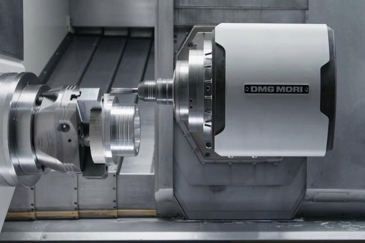
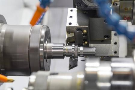 The CNC turning axis is a “digital drive unit” that controls the movement of the machine tool’s cutting tool/workpiece. Through the precise coordination of each axis, machining from simple cylinders to complex curved surfaces can be achieved. Its core axis system is mainly composed of the “X – Z axes, supplemented by the C – axis and extended by the Y – axis”. The combination of different axes determines the machining capabilities of the turning machine tool (for example, an ordinary lathe only has X/Z axes, while a turning – milling compound center has X/Z/C/Y axes).
|
Axis Type
|
Core Function
|
Motion Direction
|
Typical Application Scenario
|
Industry Adoption Rate (2025)
|
|
X-Axis
|
Controls radial movement (adjusts workpiece diameter)
|
Perpendicular to spindle axis (left/right)
|
Turning outer diameter (φ)、boring inner hole
|
100% (all CNC lathes)
|
|
Z-Axis
|
Controls axial movement (adjusts workpiece length)
|
Parallel to spindle axis (forward/backward)
|
Machining end faces、stepped shafts
|
100% (all CNC lathes)
|
|
C-Axis
|
Spindle rotational axis (achieves indexing or continuous rotation)
|
Around Z-axis (clockwise/counterclockwise)
|
Milling keyways、drilling cross holes
|
65% (turn-mill centers)
|
|
Y-Axis
|
Auxiliary radial axis (compensates for off-center machining)
|
Perpendicular to X/Z plane (up/down)
|
Machining eccentric shafts、offset grooves
|
30% (high-end turning centers)
|
Key Insight: The combination of X-Z axes covers 80% of basic turning tasks (e.g., shafts, bushings), while adding C-axis enables 90% of complex turn-mill composite processing (Source: 2025 CNC Lathe Function Configuration Report).
2. In-Depth Analysis of Core Axes
A. X-Axis: The “Diameter Controller” of Turning
- Motion Principle: Driven by ball screws and servo motors, the X-axis moves the tool rest radially (e.g., from X50 to X30 reduces the workpiece diameter by 20mm).
- Critical Parameters:
-
- Travel Range: Typically 100-500mm (depends on machine model; e.g., Haas ST-20 X-travel is 305mm).
-
- Positioning Accuracy: ±0.001-0.003mm (FANUC αi-B servo system standard).
-
- Feed Rate: 0-20,000mm/min (high feed rate for rough turning, low for finish turning).
- Typical Application:
Turning a φ50mm shaft to φ30mm: Program G01 X30 Z-50 F0.2 — X-axis moves from X50 (initial position) to X30, reducing the diameter by 20mm.
B. Z-Axis: The “Length Manager” of Turning
- Motion Principle: Moves the tool rest parallel to the spindle axis, determining the workpiece’s axial dimensions (e.g., Z-100 means machining to a length of 100mm).
- Critical Parameters:
-
- Travel Range: 200-1500mm (e.g., Okuma LB3000 Z-travel is 1200mm for long shafts).
-
- Positioning Accuracy: ±0.002-0.005mm (slightly lower than X-axis due to longer travel).
-
- Dynamic Response: Fast acceleration (0.5-1g) to avoid tool marks on end faces.
- Typical Application:
Machining a 80mm-long stepped shaft: Program G01 X40 Z-80 F0.15 — Z-axis moves from Z0 (end face) to Z-80, ensuring the shaft length meets requirements.
C. C-Axis: The “Turn-Mill Enabler” for Complex Parts
- Motion Principle: Integrates the spindle with a servo motor to achieve precise rotational positioning (indexing) or continuous rotation (synchronization with X/Z axes).
- Critical Parameters:
-
- Indexing Accuracy: ±0.005° (for FANUC 30i-MB system).
-
- Rotational Speed: 0-3000r/min (same as spindle speed for continuous cutting).
- Typical Application:
Milling a keyway on a φ25mm shaft:
-
- C-axis indexes to 0° (aligns keyway position): G00 C0.
-
- X-axis feeds to cutting depth: G01 X19 F0.1 (keyway depth 3mm: 25-6=19).
-
- Z-axis mills keyway length: G01 Z-20 F150.
D. Y-Axis: The “Eccentric Specialist” (Auxiliary Axis)
- Motion Principle: Moves the tool in a direction perpendicular to both X and Z axes, enabling off-center machining (e.g., eccentric shafts where the centerline deviates from the spindle axis).
- Typical Application:
Machining an eccentric shaft with 5mm eccentricity:
-
- Program G00 Y5 (offsets tool by 5mm from Z-axis centerline).
-
- Then execute X-Z turning: G01 X30 Z-50 F0.2 (machines the eccentric cylindrical surface).
3. Key Technologies for Axis Synergy
CNC turning quality depends on the synchronization and accuracy of multi-axis collaboration—mastering these technologies avoids defects like taper shafts or oval cross-sections.
A. X-Z Axis Linkage: For Tapers and Curves
- Principle: X and Z axes move simultaneously at a fixed ratio to machine conical or arc surfaces.
- Common Applications:
-
- Taper turning: Program G01 X40 Z-50 F0.2 (machines a taper with 1:5 taper ratio: (50-40)/2 : 50 = 5:50 = 1:5).
-
- Arc turning: Program G02 X30 Z-20 R5 F0.1 (machines a 5mm-radius convex arc on the shaft end).
- Accuracy Control:
Use “taper compensation” (G452/G453 for FANUC) to correct taper errors caused by servo lag—this reduces taper deviation by 40% (Source: CNC Axis Synchronization Technology White Paper).
B. X-C Axis Linkage: For End Face Complex Features
- Principle: C-axis rotates continuously while X-axis feeds radially, enabling machining of end face cam slots or spiral grooves.
- Example: Machining a spiral groove on a shaft end face (groove width 2mm, pitch 5mm):
G99 G54 S1000 M03 (C-axis rotation speed 1000r/min)
G00 X20 Z0 (Move to end face)
G01 X10 C0 F0.1 (Start at C0, X=20)
G01 X10 C360 F5 (C-axis rotates 360°, X stays 10—machines 5mm-pitch spiral groove)
- Key Note: Ensure C-axis and spindle speed are synchronized (use G96 constant surface speed for stable cutting).
C. Axis Precision Compensation: For Errors
- 1. Backlash Compensation:
-
- Cause: Gap between ball screw and nut leads to X-axis “play” (e.g., X-axis moves 10mm but actual movement is 10.002mm).
-
- Solution: Set backlash compensation value (e.g., 0.002mm) in machine parameters (FANUC parameter No. 1851 for X-axis).
- 2. Thermal Deformation Compensation:
-
- Cause: Long-term machining heats up ball screws, leading to Z-axis elongation (e.g., Z-axis travel 1000mm may elongate by 0.01mm).
-
- Solution: Use machine-built-in temperature sensors to automatically adjust compensation values—this reduces thermal errors by 60% (Source: Haas Thermal Compensation Guide 2025).
4. Practical Case: Machining a Tapered Shaft with C-Axis Keyway
Part Specs: φ40-φ30 tapered shaft (length 50mm), 6×6mm keyway (depth 3mm, length 20mm) — using FANUC 0i-TF turn-mill center (X/Z/C axes).
Step 1: Process & Axis Assignment
|
Process
|
Axes Used
|
Core Task
|
|
Rough Turning (Taper)
|
X-Z
|
Remove excess material, machine taper contour
|
|
Finish Turning (Taper)
|
X-Z
|
Ensure taper accuracy (1:5 ratio)
|
|
Milling Keyway
|
X-Z-C
|
C-axis indexes, X feeds depth, Z mills length
|
Step 2: Equipment & Parameters
- Tools: T0101 (external turning tool), T0303 (φ6mm end mill).
- Parameters:
-
- Turning: S2000r/min (rough), S2500r/min (finish); F0.2mm/rev (rough), F0.1mm/rev (finish).
-
- Milling: S3000r/min, F150mm/min.
Step 3: Program Snippet (Key Axis Movements Highlighted)
O0001 (Tapered Shaft with Keyway Program)
G99 G54 S2500 M03 (Set feed unit, coordinate, spindle speed)
T0101 M08 (Turning tool, coolant on)
// 1. X-Z Linkage: Rough Turning Taper
G00 X45 Z2 (X-Z move to safe position)
G71 U2 R1 (Rough cycle: X-axis depth 2mm)
G71 P10 Q20 U0.2 W0.1 F0.2
N10 G00 X30 Z0 (Taper start: X30, Z0)
G01 X40 Z-50 F0.1 (X-Z linkage: taper to X40, Z-50) // Taper machining
N20 G00 X45 Z2 (Taper end)
G70 P10 Q20 (Finish turning taper)
// 2. X-Z-C Linkage: Milling Keyway
G00 X100 Z100 (Return to origin)
T0303 M03 S3000 (Switch to end mill)
G00 X25 Z-10 C0 (C-axis indexes to 0°; X/Z move to keyway start) // C-axis positioning
G43 Z5 H03 (Tool length compensation)
G01 Z-3 F150 (X-axis direction: cut to 3mm depth) // X-axis feed
G01 Z-30 F150 (Z-axis direction: mill 20mm length) // Z-axis feed
G00 Z10 (Retract)
// Program End
G00 X100 Z100
M05 M09
M30
Step 4: Axis Movement Verification
- X-Z Linkage: Use machine simulation to check if the taper ratio (1:5) matches the drawing (X changes 10mm, Z changes 50mm).
- C-Axis Indexing: After programming C0, use a dial indicator to confirm the spindle is at 0° (error <0.005°).
5. Common Axis-Related Problems & Solutions
1. X-Axis: Oval Cross-Section (Workpiece Not Round)
- Cause: X-axis backlash is uncompensated, or servo motor gain is too low.
- Solution:
-
- Measure backlash with a dial indicator (push X-axis left/right, record gap) and set compensation value (e.g., 0.003mm) in parameters.
-
- Increase X-axis servo gain (FANUC parameter No. 2021) by 10-15% to improve response.
2. Z-Axis: Tapered Shaft (Length Direction Diameter Deviation)
- Cause: Z-axis thermal deformation (screw elongation) or uneven wear.
- Solution:
-
- Run the Z-axis empty for 10 minutes (preheat) before machining to stabilize temperature.
-
- Replace worn ball screws if wear exceeds 0.01mm (check with a laser interferometer).
3. C-Axis: Keyway Position Deviation (Indexing Error)
- Cause: C-axis encoder error or spindle clamping force is too low.
- Solution:
-
- Calibrate C-axis encoder (use FANUC’s “encoder reset” function) to correct indexing error.
-
- Increase spindle clamping force (parameter No. 3204 for FANUC) to prevent rotation during milling.
6. Q&A: High-Frequency Questions About Turning Axes
Q1: How to check if X/Z axis accuracy meets requirements?
- Use a laser interferometer to measure positioning accuracy (e.g., Renishaw XL-80). For small workshops, use a “test bar”:
-
- Turn a φ50×100mm test bar with X-Z linkage.
-
- Measure diameter at Z0 and Z100 with a micrometer—if deviation >0.005mm, axis accuracy needs adjustment.
Q2: Why do some turning centers add a Y-axis? Is it necessary?
- Y-axis is for eccentric machining (e.g., automotive crankshafts with eccentric journals). For 90% of standard parts (shafts, bushings), X-Z axes are sufficient. Only choose Y-axis if you process >100 eccentric parts monthly—its cost adds ~30% to the machine (Source: CNC Lathe Cost-Benefit Analysis 2025).
Q3: What’s the difference between C-axis and spindle rotation (M03)?
- M03: Spindle rotates at a fixed speed (for turning, no precise positioning).
- C-axis: Spindle rotates with servo control (can index to specific angles, e.g., C90° for keyway milling, or rotate continuously for spiral grooves).
Final Thought
CNC turning axes are the “skeleton” of the machine—X-Z axes lay the foundation for basic turning, while C/Y axes extend capabilities to complex composite processing. The key to mastering them is not just memorizing axis movements, but understanding how to synchronize axes for accuracy (e.g., X-Z linkage for tapers) and how to compensate for errors (e.g., backlash, thermal deformation).
Have you encountered axis-related issues like oval workpieces or C-axis indexing errors? Or do you need guidance on programming for specific axes (e.g., Y-axis eccentric turning)? Share your questions in the comments—I’ll provide targeted solutions!