Automotive taillight components are among the most demanding plastic parts in vehicle manufacturing — requiring optical clarity, precise dimensional control, and reliable performance under thermal cycling, UV exposure, and road vibration over the vehicle’s service life.
For automotive Tier-1 and Tier-2 suppliers, brand owners, and OEM procurement teams, sourcing taillight components involves assessing whether a manufacturing partner can deliver optical-grade injection molding, consistent color appearance across production batches, and full compliance with SAE, DOT, or ECE regulatory requirements.
Goldcattle provides custom automotive taillight component manufacturing services — from optical lens molding and LED housing production to light guide machining and multi-component assembly. Our process integrates precision mold development, optical-grade injection molding, and documented quality verification to support automotive supply chain requirements.
What Are Automotive Taillight Components?
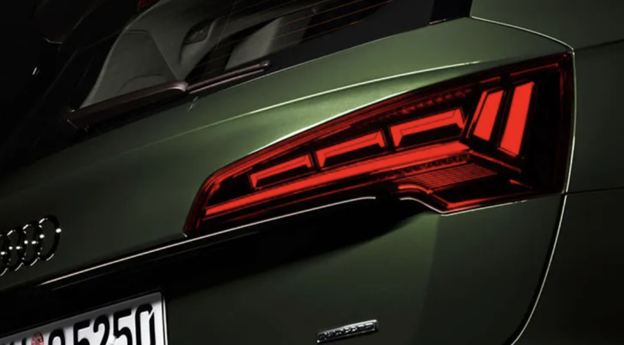
Automotive taillight components are the precision-engineered plastic parts that form a vehicle’s rear lighting system — including optical lenses, LED housings, light guides, reflectors, bezels, and structural mounting brackets. These components must meet strict requirements for optical performance (light transmittance, color consistency), environmental durability (UV resistance, thermal cycling, moisture sealing), and dimensional precision (assembly fit and sealing integrity). In modern vehicles, taillight systems have evolved from simple lamp-and-lens assemblies to complex multi-function modules integrating LED arrays, dynamic turn indicators, and electronic sensors.
In summary, automotive taillight components are high-precision optical and structural plastic parts that must simultaneously satisfy optical performance specifications, environmental durability requirements, and automotive-grade dimensional tolerances — making them among the most demanding injection-molded components in vehicle manufacturing.
Our Automotive Lighting Manufacturing Capabilities
Optical Lens Injection Molding
Optical lenses for taillights require flawless transparency, precise light distribution, and long-term UV stability. Our lens molding capabilities:
- Materials: Optical-grade PMMA (≥92% light transmittance) and UV-stabilized PC (≥88% light transmittance with coating)
- Mold precision: Optical-grade mold inserts with surface roughness Ra ≤0.02 μm; high-precision optical molds use S136 stainless steel at HRC 58–62 for mirror-finish cavity surfaces
- Molding environment: Dedicated white-room molding cell with humidity and temperature control to prevent contamination-related optical defects
- Dimensional tolerance: ±0.05 mm on lens thickness (2–4 mm typical); ±0.1 mm on general positions
- UV protection: UV-resistant hard coating applied in-line; ΔE <2 after 3,000 hours UV exposure per applicable test standards
- Key quality parameters verified: Light transmittance (ASTM D1003), haze, weld line position, and birefringence (residual stress)
Optical-grade lens injection molding for PC and PMMA means controlling haze per ASTM D1003, weld line position, and residual-stress birefringence — not just dimensional compliance. The engineering goal is to force weld lines to form outside the optical Zone A by controlling flow-front convergence temperature and filling sequence. For PMMA, light transmittance of ≥92% is achievable under optimized molding conditions with proper material drying, controlled melt temperature, and adequate mold venting.
Optical lens injection molding for automotive tail lamps requires simultaneous control of dimensional tolerance (±0.05 mm), optical performance (transmittance, haze, weld line position per ASTM D1003), and long-term UV stability — making material selection, mold precision, and clean-room processing equally critical.
LED Housing Components
LED housings for taillights provide structural support, heat dissipation, and precise alignment for LED PCBs and optical elements. Our manufacturing capabilities:
- Materials: PC/ABS blends, heat-resistant PC (for high-brightness LED applications), glass-filled PP for cost-optimized designs
- Tolerances: ±0.1 mm on mounting features; ±0.05 mm on LED alignment features
- Process: Multi-cavity injection molding with hot runner systems for consistent shot-to-shot quality
- Vibration resistance: Component design verified for automotive vibration profiles
Light Guide Manufacturing
Light guides use total internal reflection to distribute LED light evenly along the component‘s length — requiring flawless optical surfaces and precise geometry:
- Materials: Optical-grade PMMA for maximum light transmission
- Mold requirements: Polished cavity surfaces with Ra ≤0.05 μm; no surface defects permitted in light-transmitting zones
- Process control: Mold temperature uniformity within ±2°C to prevent inconsistent refractive properties
- Quality verification: Light uniformity measurement along full guide length; no dark spots or hot spots permitted
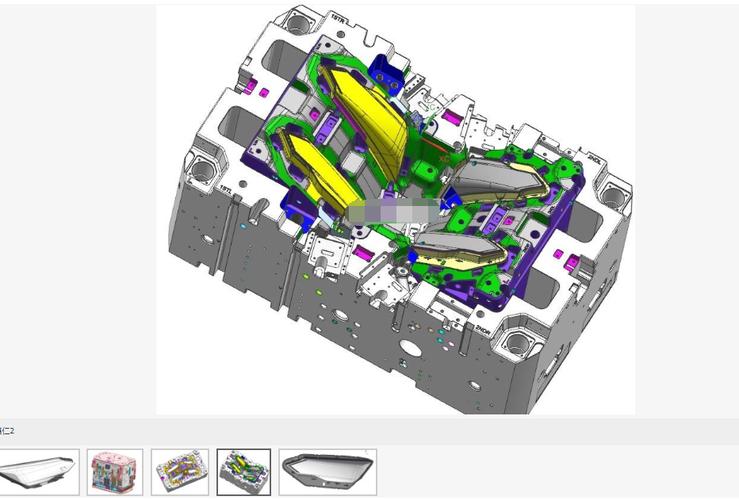
Precision Mold Development
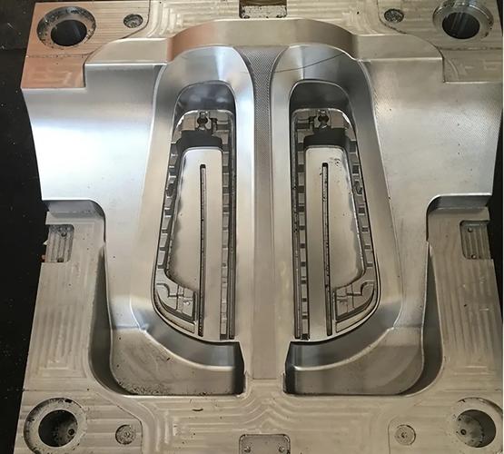
Every automotive lighting component begins with the mold. For optical-grade parts, mold quality directly determines part quality and production yield:
- Mold design: DFM analysis with mold flow simulation to predict weld line formation, optimize gate position, and verify cavity filling
- Mold manufacturing: High-speed CNC machining + wire EDM + precision grinding for cavity/core fabrication
- Mold materials: S136/420SS stainless steel (HRC 58–62) for optical lens molds requiring mirror-finish surfaces; H13 hot work tool steel (HRC 48–52) for housing molds
- Mold validation: First-article inspection with full dimensional report; mold trial with optical verification of lens quality
- Multi-shot capability: Multi-color lens molding via 2K/3K injection process for taillight lenses requiring multiple color zones in a single part
Assembly & Sub-Component Integration
Beyond individual components, we offer value-added assembly and integration services that reduce customer-side complexity and supply chain management:
- Assembly processes: Ultrasonic welding, hot plate welding, adhesive bonding, snap-fit assembly
- Integration: LED PCB insertion, connector assembly, gasket installation
- Testing: Functional light test, leak test (per IP rating specification), dimensional check on assembled units
- Documentation: Assembly process documentation, in-process inspection records, final QA sign-off per shipment
From optical lens molding with polished S136 mold inserts to multi-cavity housing production and final assembly, our integrated manufacturing capability means we can deliver complete taillight sub-assemblies — reducing our customers’ supply chain complexity and qualification burden.
Materials for Automotive Taillight Systems
Material selection directly determines whether a taillight component meets optical, mechanical, and environmental requirements — and remains compliant over the vehicle‘s 10–15 year expected service life.
| Material | Key Properties | Typical Taillight Application | Notes |
|---|---|---|---|
| PMMA (Acrylic) | ≥92% light transmittance; excellent optical clarity; UV resistant; scratch resistant | Outer lenses; light guides; optical elements | PMMA is the most common optical lens material, known for high clarity and efficient mass production capability through injection molding. PMMA achieves higher light transmittance (around 92% or higher for specific grades) and good thermal performance. However, PMMA is more brittle with lower impact resistance, making it less suitable where lenses might experience shocks or impacts |
| Polycarbonate (PC) | ≥88% light transmittance; high impact resistance; heat resistant to ~130°C | Outer lenses (impact-critical applications); LED housings; internal structural parts | PC provides superior impact resistance compared to PMMA but requires UV-stabilization coating to prevent yellowing over time |
| PC/ABS Blends | Good balance of impact resistance, heat resistance, and processability; ABS provides chemical resistance | Taillight housings; mounting brackets; structural bezels | Commonly used for non-optical structural components; offers cost-efficiency |
| Heat-Resistant PC | Maintains mechanical properties at elevated temperatures (near high-brightness LED arrays) | LED mounting plates; high-temperature housing sections | Required for applications where LED heat dissipation raises local housing temperature |
| PBT (Polybutylene Terephthalate) | Good dimensional stability; chemical resistance; heat resistance | Connector housings; mounting brackets | Used for components requiring dimensional stability under thermal cycling |
PMMA has been widely used in automotive tail lamps for over 70 years, with modern tail lights increasingly emphasizing optical and branded design. The choice between PMMA and PC for outer lenses depends on the specific application: PMMA for maximum optical clarity in protected positions; PC where impact resistance is paramount, with UV coating to prevent yellowing.
In summary, material selection for automotive taillight components must balance optical performance (PMMA for ≥92% transmittance in protected positions), impact resistance (PC where mechanical stress is expected), and cost-efficiency (PC/ABS for non-optical structural components) — with all materials validated for UV stability and thermal cycling performance over the vehicle’s service life.
Key Engineering Challenges in Automotive Lighting Manufacturing
Automotive taillight components present unique manufacturing challenges that separate experienced automotive lighting suppliers from general injection molders.
Challenge 1: Optical Weld Line Control
Weld lines form where two melt flow fronts meet during injection — such as when melt flows around a core pin and recombines. In optical lenses, weld lines in the light-transmitting zone cause visible lines, reduced local transmittance, and light scattering. Optical lens and headlight cover manufacturing has a zero-tolerance policy towards weld lines and birefringence.
Optical-grade lens injection molding fundamentally requires controlling haze, weld lines, and residual-stress birefringence beyond just dimensional compliance. The engineering goal is to force the weld line to form outside Zone A — the critical optical zone — by controlling flow-front convergence temperature and filling sequence.
For lenses that still exhibit weld lines in the optical zone, alternative approaches such as injection-compression molding can be applied. Studies show that injection-compression molding reduces weld line severity through more uniform pressure distribution and lower residual stress compared to conventional injection molding.
Challenge 2: Contamination Control in Optical Molding
For optical-grade lenses, even micro-scale contamination creates cosmetic rejects. Contamination elimination requires a dedicated clean molding cell — not a general-purpose molding floor. Contamination can originate from material handling (dust ingress), machine maintenance (oil mist), mold surface residue, or operator contact. Optical-grade molding requires a clean-room environment to prevent contamination-related defects that would compromise lens clarity and cosmetic quality.
Challenge 3: UV Degradation & Yellowing
Taillight lenses are continuously exposed to solar UV radiation for the vehicle’s lifetime. Without adequate UV stabilization, PC lenses will yellow within 18–36 months — degrading both appearance and light transmittance. PC lenses require UV-stabilized coating applied in a controlled process, with yellowing resistance verified through accelerated weathering tests (ΔE <2 after 3,000 hours UV exposure per applicable test standards).
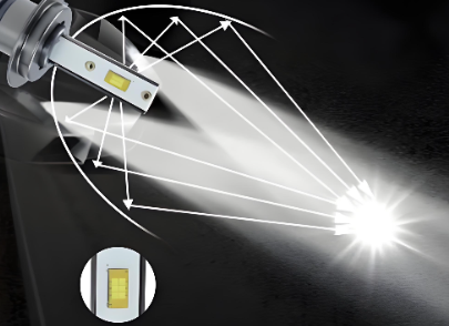
Challenge 4: Thermal Management for LED Applications
Modern LED taillights concentrate heat in small areas. Housing materials must withstand local temperatures without deformation, and optical components must maintain dimensional stability through repeated thermal cycling from ambient to operating temperature. Material selection must account for the specific LED configuration and power density.
Challenge 5: Color Consistency Across Production Batches
Taillight color is regulated — per SAE J578c, tail lamps and stop lamps must be red. For multi-cavity production spanning months or years, maintaining consistent color across every batch requires rigorous material lot control, consistent processing parameters, and documented color measurement on representative samples per batch.
The key factor distinguishing experienced automotive lighting component manufacturers from general injection molders is not equipment alone — it is the systematic engineering approach to weld line control, contamination prevention, UV protection, thermal management, and batch-to-batch consistency that determines whether parts consistently meet automotive requirements across production runs.
How We Ensure Optical Quality & Consistency
For automotive lighting components, quality verification goes far beyond dimensional inspection — optical performance, surface quality, and environmental durability must all be validated with documented test data.
Optical Verification
| Quality Parameter | Test Method / Standard | Acceptance Criteria | Verification Frequency |
|---|---|---|---|
| Light transmittance | ASTM D1003 | ≥92% for PMMA; ≥88% for coated PC | Per batch |
| Haze | ASTM D1003 | <1% for optical lenses | Per batch |
| Color consistency | Spectrophotometer; SAE J578c (color specification) | Red per SAE J578c for tail/stop lamps; ΔE ≤1.0 batch-to-batch | Per batch and per material lot change |
| Weld line position | Visual inspection under controlled lighting; optical simulation verification | No weld line in Zone A (optical zone) | Mold qualification and periodic audit |
| Surface quality | Visual inspection under controlled magnification and lighting | No scratches, contamination, sinks, flow marks, or surface defects in visible zones | 100% inspection for optical lenses |
Mold Flow & Optical Simulation
Before cutting mold steel, we use mold flow simulation to predict and optimize material flow, identify potential weld line locations, and verify cavity filling. For optical lenses, optical simulation validates that the lens geometry will achieve the target beam pattern before tooling commitment. This front-end engineering eliminates costly mold rework and ensures first-article optical quality.
Weld line detection and prevention at an early simulation stage is essential — parts like lenses, optical housings, and headlight covers have a zero-tolerance policy towards weld lines. When such defects are discovered after physical development begins, costly tool iterations and rework are the result.
Process Control for Optical Injection Molding
Optical-grade molding requires balanced cooling circuits to eradicate sink marks, warpage, and weld lines through uniform heat extraction, as well as precision venting and low-stress ejection systems that prevent birefringence or surface scuffing on the molded lens. Clean-room molding cells with humidity and temperature control further prevent contamination-related optical defects.
In summary, optical quality in automotive taillight component manufacturing is ensured through three integrated layers — pre-production simulation to prevent defects, in-process molding control to maintain stability, and post-production optical verification to validate conformance — with documented data supporting every validation step.
Automotive Quality Standards & Compliance
For automotive OEM and Tier-1 procurement, supplier qualification depends on demonstrated compliance with industry-specific standards — not generic quality claims.
IATF 16949 & Quality Management
IATF 16949 is the global automotive industry quality management system standard, incorporating ISO 9001 and adding automotive-specific requirements for defect prevention, process control, and continuous improvement. Automotive lighting components are manufactured under a quality management system aligned with IATF 16949 requirements, ensuring the process controls, risk management practices, and traceability systems required by automotive supply chains.
Production Part Approval Process (PPAP)
PPAP is the standardized process by which automotive suppliers demonstrate that their production process consistently produces parts meeting customer specifications. Our PPAP support documentation package includes dimensional reports, material certifications, process flow diagrams, process FMEA, control plans, measurement system analysis (MSA), and appearance approval reports (AAR).
SAE & Regulatory Standards
Taillight components must be manufactured to support the final lamp assembly‘s compliance with applicable regulations:
- SAE J585e / J585d — Tail lamp photometric requirements
- SAE J578c — Color specification for signaling devices (tail lamps and stop lamps must be red)
- SAE J576 — Plastic lens material weathering and durability requirements
- DOT FMVSS 108 — U.S. federal motor vehicle safety standard for lamps and reflective devices
- ECE R7 / R48 — European regulations for vehicle lighting
In summary, automotive taillight component manufacturing must be conducted within a quality system aligned with IATF 16949 requirements, with PPAP documentation available to support customer part approval, and with manufacturing processes designed to produce components that meet SAE/DOT/ECE regulatory requirements at the finished lamp assembly level.
Customization & OEM Services for Automotive Lighting
For automotive lighting brand owners, Tier-1 suppliers, and OEM procurement teams, the ability to customize components to specific vehicle platforms — rather than select from a catalog — determines whether a supplier can support program-based sourcing.
What We Customize
| Customization Dimension | Capability |
|---|---|
| Component Design | Custom optical lenses (aspheric, Fresnel), housings, light guides, reflectors, bezels — per customer CAD or specification |
| Material Specification | PMMA, PC, PC/ABS, heat-resistant grades — specified per application requirements and OEM material standards |
| Optical Performance | Custom beam pattern, light uniformity, color temperature — verified through optical simulation before tooling |
| Surface Finish | Polished optical surfaces, UV hard coating, anti-fog coating, blackout masking |
| Color Matching | Color matching for housings and bezels per customer color specification; spectrophotometer verification |
| Integration Level | Individual components or complete sub-assemblies with PCB integration, connector installation, and functional testing |
Our OEM/ODM Process
- Design Review & DFM — CAD file receipt; optical, structural, and mold DFM analysis within 24–48 hours
- Simulation & Validation — Mold flow simulation for filling/optical analysis; optical simulation for beam pattern verification
- Prototype Development — Rapid prototype for design validation; production-intent samples from prototype tooling
- Mold Manufacturing & Trial — Production mold build; mold trial with full dimensional and optical validation
- PPAP Submission — Full PPAP documentation package including dimensional report, material certs, process capability data
- Mass Production & Delivery — Production ramp-up with in-process quality monitoring; documented batch traceability
Common Taillight Component Defects & Our Solutions
| Defect | Root Cause | Commercial Impact | Our Solution |
|---|---|---|---|
| Weld lines in optical zone | Dual flow fronts converging at core pin or around hole; insufficient melt temperature at convergence point | Visible cosmetic line; optical distortion; reduced local light transmittance → part rejection | Mold flow simulation to predict weld line location before tooling; optimize gate position and filling sequence to move weld line outside Zone A; injection-compression molding for lenses with unavoidable weld lines |
| Black specks / Contamination | Degraded material residue in hot runner or barrel; dust ingress; carbonized material | Highly visible defect in transparent/optical parts → 100% rejection of affected parts | Dedicated clean-room molding cells; material drying protocol; regular screw/barrel cleaning schedule; mold surface inspection between shots for high-spec lenses |
| Sink marks | Uneven wall thickness causing differential shrinkage rates during cooling | Visible surface depression on cosmetic surfaces; dimensional deviation in critical areas | Optimized gate location and packing profile to ensure uniform material compression; balanced cooling circuit design to ensure uniform heat extraction |
| Flow marks / Surface ripples | Premature material solidification during cavity filling; insufficient mold temperature; excessive injection speed variation | Visible surface defect on Class-A surfaces → cosmetic rejection | Optimized melt/mold temperature profile; sequential valve gate control for uniform flow front advancement |
| Warpage | Differential shrinkage due to non-uniform cooling or inherent geometry asymmetry | Assembly misfit; sealing surface non-conformance → leak path or mechanical interference | Mold flow simulation to predict and compensate for warpage; conformal cooling design for uniform heat extraction; post-mold fixturing where needed |
| UV yellowing (PC lenses) | Inadequate UV-stabilization coating thickness or coverage; coating adhesion failure | Progressive degradation of lens appearance and light transmittance → warranty claim risk | UV-resistant hard coating with verified thickness and coverage; accelerated weathering test (ΔE <2 after 3,000 hours UV per applicable standards) on representative samples per production batch |
| Color inconsistency batch-to-batch | Material lot variation; inconsistent masterbatch dosing; processing temperature variation | Visible color mismatch between production batches → assembly-line rejection | Material lot pre-qualification; spectrophotometer color measurement per batch with defined ΔE limits; documented color measurement data with each shipment |
These failure modes are not theoretical — they are well-documented in automotive lighting manufacturing. Our engineering approach prevents them through mold flow simulation before tooling, clean-room process control during production, and documented quality verification on every batch — reducing total quality cost and ensuring that our customers receive production-ready components, not inspection-sorted lots.
Case Study — EV LED Taillight Lens & Housing Project
Project: LED Taillight Lens and Housing Assembly for Electric Vehicle Platform
Industry: Automotive — EV OEM
Material: Outer lens: UV-stabilized PC with hard coating; Housing: PC/ABS; Light guide: Optical-grade PMMA
Challenge: The lens required ≥88% light transmittance in the visible spectrum with UV-stabilization validated to ΔE <2 after 3,000 hours UV exposure. Weld lines in the lens optical zone due to multiple core pin locations resulted in unacceptable cosmetic defects. Housing required dimensional stability within ±0.1 mm across 150 mm length to ensure proper sealing with body panel. Combined volume across left-hand and right-hand components in symmetrical tooling: 50,000 units annually.
Our Solution:
- Performed mold flow simulation to analyze weld line formation; optimized gate position and filling sequence to move weld line from optical Zone A to non-critical peripheral area
- Manufactured optical mold inserts from S136 stainless steel (Austria Böhler grade), mirror-polished to Ra ≤0.02 μm for flawless lens surface quality
- Implemented dedicated optical molding cell with humidity control, HEPA filtration, and automated material handling to eliminate contamination risk
- Applied UV-resistant hard coating with automated thickness control; validated coating adhesion per standardized cross-hatch test
- Developed symmetrical multi-cavity tooling for left and right-hand components in single mold cycles
- Delivered full PPAP documentation including dimensional reports, material certificates, and optical transmittance test data
Results:
- Weld line successfully relocated to non-optical zone; zero weld-line-related rejections in production
- Lens light transmittance: 89.5% average (above the 88% requirement)
- UV resistance validated: ΔE 1.2 after 3,000 hours accelerated weathering (below the <2 specification)
- First-article acceptance rate: 100%
- Annual production of 50,000 sets with zero field returns related to optical degradation after 2 years in service
This project demonstrates our integrated approach to automotive lighting component manufacturing — combining optical simulation to prevent defects before tooling, precision mold manufacturing with mirror-finish cavities, clean-room molding for contamination-free production, and PPAP documentation to support OEM approval. When taillight performance requirements demand optical clarity, environmental durability, and documented quality, our engineering and manufacturing systems deliver.
Why Choose Our Automotive Taillight Component Manufacturing
For automotive procurement teams, selecting a taillight component manufacturing partner requires evaluating more than unit price. The cost of inadequate quality — optical defects, UV degradation, sealing failures — accrues over the vehicle’s service life and exposes the brand to warranty claims and regulatory non-compliance. Our manufacturing service is structured to minimize that lifecycle risk:
- Optical-Grade Capability: Dedicated clean-room molding cells; optical simulation before tooling; PMMA ≥92% and coated PC ≥88% transmittance; weld line control through mold flow optimization
- Precision Mold Manufacturing: In-house mold design, CNC machining, wire EDM, and polishing; optical mold inserts with Ra ≤0.02 μm mirror finish using S136 stainless steel
- Material Expertise: PMMA, PC, PC/ABS, heat-resistant grades — specified per application requirements with documented material certification
- Automotive Quality System: IATF 16949-aligned quality management; PPAP documentation support; SAE J585/J578/J576 standards knowledge
- Verification Capabilities: CMM dimensional inspection; spectrophotometer color measurement; optical transmittance and haze testing per ASTM D1003; accelerated weathering test
- Program Support: DFM review within 24–48 hours; prototype to mass production transition; JIT delivery capability; documented batch traceability
In summary, the right automotive taillight component manufacturing partner delivers more than parts — they provide optical engineering capability, automotive-grade quality systems, PPAP documentation, and reliable production that minimize total cost of quality across the component’s service life.
FAQ — Automotive Taillight Component Manufacturing
Q1: What materials are used for automotive taillight lenses?
The two primary materials for automotive taillight lenses are PMMA (acrylic) and polycarbonate (PC). PMMA offers ≥92% light transmittance, excellent optical clarity, and natural UV resistance — making it the preferred choice for optical lenses in protected positions where maximum clarity is required. PC offers ≥88% light transmittance with superior impact resistance — making it suitable for lenses that may experience mechanical stress or impact, but it requires UV-stabilization coating to prevent yellowing over time. PMMA is more brittle and scratches more easily; PC provides higher impact resistance but lower natural optical clarity than PMMA.
Q2: What is the best material for automotive optical lenses?
For automotive optical lenses, PMMA is typically the best choice when maximum light transmittance (≥92%) and optical clarity are the primary requirements, and the lens is in a protected position. For lenses requiring impact resistance, PC with UV-stabilization coating is preferred. The selection depends on the specific application requirements: optical performance, mechanical stress exposure, and cost targets.
Q3: How are automotive taillight lenses manufactured?
Automotive taillight lenses are manufactured through optical-grade injection molding — a specialized process requiring polished mold inserts with surface roughness Ra ≤0.02 μm, clean-room molding environments to prevent contamination, high-precision injection molding machines with controlled melt temperature and injection speed, and post-molding UV coating for PC lenses. The mold is the most critical element: optical mold inserts are typically manufactured from S136 stainless steel hardened to HRC 58–62 and mirror-polished to achieve the required surface finish. Optical simulation and mold flow analysis are performed before tooling to predict and prevent defects such as weld lines in the optical zone.
Q4: How do you control weld lines in optical lenses?
Weld lines are controlled through mold flow simulation before tooling to predict where melt flow fronts will converge. Gate position and filling sequence are optimized to move weld lines outside Zone A — the critical optical zone. For lenses where weld lines cannot be entirely eliminated, injection-compression molding may be applied to reduce weld line severity through more uniform pressure distribution during the molding process.
Q5: What automotive standards apply to taillight components?
Key standards include: SAE J585e/J585d for tail lamp photometric performance; SAE J578c for color specifications (tail and stop lamps must be red); SAE J576 for plastic lens material weathering and durability; DOT FMVSS 108 for U.S. federal lamp requirements; and ECE R7/R48 for European vehicle lighting regulations. Component manufacturers must produce parts that support the finished lamp assembly‘s compliance with these standards.
Q6: What is PPAP and why is it needed for automotive lighting?
PPAP (Production Part Approval Process) is the standardized automotive industry process by which suppliers demonstrate that their production process consistently produces parts meeting all customer specifications. For taillight components, the PPAP documentation package typically includes dimensional reports, material certifications, process flow diagrams, process FMEA, control plans, measurement system analysis (MSA), and appearance approval reports (AAR). PPAP is a standard requirement for OEM and Tier-1 automotive supply chains.
Q7: How do you ensure color consistency across production batches?
Color consistency is ensured through material lot pre-qualification with spectrophotometer verification, consistent masterbatch dosing control, documented color measurement per batch with defined ΔE limits, and stable processing parameters that prevent temperature-induced color variation. Tail lamp color must be red per SAE J578c.
Q8: Can you manufacture both left-hand and right-hand taillight components?
Yes. We use symmetrical multi-cavity tooling to produce left-hand and right-hand components in single mold cycles — ensuring identical processing conditions and quality consistency between LHD and RHD parts. This approach improves production efficiency and reduces tooling cost compared to separate molds for each side.
Ready to develop your automotive taillight component project?
Upload your CAD file or component specification.
→ DFM review and tooling analysis within 24–48 hours
→ Quote within 24 hours
→ PPAP documentation support available
📐 Optical Molding
PMMA lenses with ≥92% transmittance; PC lenses with UV-stabilization and ΔE <2 after 3,000h UV exposure
🔍 Verification
CMM dimensional inspection; ASTM D1003 optical testing; spectrophotometer color measurement
🛠️ Materials
PMMA, PC, PC/ABS, heat-resistant grades; full material certification with every order
📋 Standards
SAE J585, SAE J578c, SAE J576; FMVSS 108 / ECE R7 aligned manufacturing
⚙️ Processes
Optical-grade injection molding; mold flow simulation; UV coating application; multi-component assembly
📄 Documentation
PPAP support; dimensional reports; material certs; optical test data; batch traceability documentation