Chapter 1 Classification of CNC Machining Defects and Core Influencing Factors
1.1 Core Classification of Defects (by Quality Dimension)
|
Defect Category
|
Included Types
|
Core Impacts
|
|
Dimensional Accuracy Defects
|
Dimensional deviation, unstable dimensions, batch dimensional drift
|
Part assembly failure, inability to achieve functionality
|
|
Surface Quality Defects
|
Excessive roughness, chatter marks, scratches, built-up edge (BUE)
|
Poor sealing performance, unqualified appearance, reduced fatigue life
|
|
Form and Position Defects
|
Flatness error, coaxiality error, perpendicularity error
|
Abnormal fitting clearance, reduced transmission accuracy
|
|
Tool-Related Defects
|
Tool chipping, excessive wear, machining chatter
|
Machining interruption, precision loss, increased costs
|
|
Equipment-Related Defects
|
Inaccurate positioning, large repeat positioning error, abnormal noise
|
Batch scrapping, shortened equipment service life
|
1.2 Core Influencing Factors of Defects
- Process Level: Improper matching of cutting parameters (spindle speed, feed rate, depth of cut), errors in machining program writing (e.g., incorrect tool compensation settings);
- Equipment Level: Insufficient spindle rigidity, wear of feed system, reduced guideway precision, delayed response of servo system;
- Tool Level: Mismatch between tool material and workpiece, dull tool edge, tool holder clamping error, incorrect tool length compensation;
- Fixture Level: Deviation of fixture positioning datum, insufficient clamping force (or excessive force causing workpiece deformation), fixture wear;
- Environment Level: Temperature fluctuations (causing thermal deformation of machine tool/workpiece), excessive humidity (affecting electrical system), vibration interference (e.g., resonance from surrounding equipment);
- Operation Level: Omission of first-piece inspection, improper workpiece clamping, tool presetting error.
Chapter 2 Detailed Explanation of Common Defects (Phenomena + Causes + Solutions + Prevention)
2.1 Dimensional Accuracy Defects
2.1.1 Defect 1: Dimensional Deviation (Single dimension exceeding tolerance range)
- Typical Phenomena:
- Core Causes:
-
- Programming errors: Incorrect input of tool compensation values (e.g., 0.1mm missing in radius compensation), offset of coordinate system setting (e.g., X-axis deviation in G54 coordinate);
-
- Tool factors: Tool wear (e.g., 0.008mm wear on the edge of a carbide tool after machining 100 pieces), tool thermal elongation (spindle heat during high-speed machining causing tool lengthening);
-
- Fixture factors: Wear of fixture positioning surface (e.g., center offset of workpiece due to wear of V-block), insufficient clamping force (micro-movement of workpiece during machining);
-
- Equipment factors: Wear of ball screw (excessive pitch error), contamination of linear scale (inaccurate feedback signal).
- Detection Tools:
- Solution Steps:
-
- Prioritize checking tool compensation and coordinate system: Re-measure tool length/radius, verify the deviation between G54/G55 coordinates and workpiece datum;
-
- Inspect tool condition: Observe if the tool edge is dull, measure the actual tool dimension with a tool presetter, and replace the tool if wear exceeds the limit;
-
- Verify fixtures: Detect the flatness of the fixture positioning surface with a dial indicator, and check for micro-movement of the workpiece with a lever indicator after clamping;
-
- Calibrate equipment: If batch deviation occurs, contact maintenance personnel to detect the pitch error of the ball screw, clean the linear scale, and re-calibrate it.
- Preventive Measures:
-
- Conduct full-dimensional inspection after the first piece is processed, and start mass production only after confirmation of qualification;
-
- Sample-check dimensions every 50-100 pieces (adjusted according to workpiece material) to monitor the tool wear trend;
-
- Regularly (e.g., monthly) clean the linear scale and check the lubrication status of the ball screw.
2.1.2 Defect 2: Unstable Dimensions (Large dimensional fluctuation of parts in the same batch)
- Typical Phenomena:
- Core Causes:
-
- Unstable servo system: Improper setting of servo motor gain parameters, leading to “overshoot” or “lag” during feed axis movement;
-
- Failure of cooling system: Insufficient cooling of spindle or workpiece, thermal deformation caused by temperature fluctuation (e.g., the length of an aluminum alloy workpiece may elongate by 0.01mm when the temperature rises by 5℃ during machining);
-
- Loose tool clamping: Excessive fit clearance between tool holder and spindle (e.g., wear of HSK tool holder taper), radial runout of tool during machining;
-
- Fluctuation of power grid voltage: Unstable voltage during peak power consumption in the workshop, affecting the output torque of the servo motor.
- Solution Steps:
-
- Observe the machining process: Detect the current fluctuation of the servo motor with an oscilloscope; if the fluctuation exceeds ±5%, contact electricians to adjust the power grid or optimize servo parameters;
-
- Inspect the cooling system: Measure the cutting fluid temperature (should be ≤35℃ under normal conditions); if the temperature is too high, clean the cooling water tank and replace the cutting fluid;
-
- Detect tool holder fit: Inspect the tool holder taper with a taper gauge, replace it if wear exceeds the limit, and ensure no oil contamination during tool holder installation;
-
- Environmental control: If the workshop temperature fluctuation exceeds ±3℃ per day, install a constant-temperature air conditioner or add a heat shield to the machine tool.
- Preventive Measures:
-
- Check the flow rate and pressure of the cooling system before starting the machine every day, and clean the filter of the cooling water tank once a week;
-
- Regularly (e.g., quarterly) calibrate servo system parameters and record key values such as gain and integration time;
-
- Preheat the machine tool for 1 hour in advance when machining high-precision parts to reduce thermal deformation.
2.2 Surface Quality Defects
2.2.1 Defect 1: Excessive Surface Roughness (Ra value higher than drawing requirements)
- Typical Phenomena:
- Core Causes:
-
- Improper cutting parameters: Excessively high feed rate (e.g., feed rate >0.2mm/r when milling aluminum alloy), excessively low spindle speed (e.g., spindle speed <1000r/min when machining steel parts);
-
- Poor tool condition: Chipped tool edge, dull tool (excessively large edge radius), incorrect tool material selection (e.g., using high-speed steel tools to machine hardened steel);
-
- Insufficient cooling: Cutting fluid not fully sprayed to the cutting area, leading to the formation of built-up edge (especially when machining low-carbon steel);
-
- Machine tool vibration: Wear of spindle bearings (radial runout >0.005mm), excessive clearance between worktable and guideway.
- Solution Steps:
-
- Optimize cutting parameters: For steel parts, increase the spindle speed (e.g., from 1000r/min to 1500r/min) and reduce the feed rate (e.g., from 0.15mm/r to 0.08mm/r); for aluminum alloy, adopt high-speed and low-feed machining (spindle speed 3000-5000r/min, feed rate 0.05-0.1mm/r);
-
- Replace tools: Select coated tools (e.g., TiAlN-coated carbide tools), ensure the tool edge is sharp, and regrind the tool if necessary;
-
- Improve cooling: Adjust the angle of the cutting fluid nozzle to ensure the cutting fluid covers the contact point between the tool edge and the workpiece; if BUE is severe, replace with oil-based cutting fluid (better lubricity than water-based cutting fluid);
-
- Suppress vibration: Detect the radial runout of the spindle, replace bearings if the runout exceeds the limit; adjust the guideway clearance (via gibs or preloading devices).
- Preventive Measures:
-
- Develop a cutting parameter table based on workpiece material (e.g., Table 1 attached), avoiding adjustments based on experience alone;
-
- Inspect the tool edge condition before each tool change, and check for chips or dullness with a magnifying glass;
-
- Check the cutting fluid concentration (with a refractometer) every week to ensure the concentration is 8%-12% (for water-based fluids).
2.2.2 Defect 2: Machining Chatter Marks (Periodic ripples on the surface)
- Typical Phenomena:
- Core Causes:
-
- Insufficient rigidity: Poor workpiece rigidity (e.g., thin-walled parts with thickness <5mm), excessive tool overhang (e.g., tool holder extending >100mm from the spindle), low spindle rigidity of the machine tool;
-
- Resonance of cutting parameters: Spindle speed is close to the natural frequency of the machine tool (e.g., the natural frequency of the machine tool is 200Hz, and the frequency is 200Hz when the spindle speed is 12000r/min);
-
- Clearance of feed system: Excessive clearance between ball screw and nut (e.g., >0.01mm), leading to “idle stroke” during reverse movement;
-
- Improper clamping force: Excessive clamping force on thin-walled parts causing deformation, and rebound after machining producing chatter marks; insufficient clamping force causing vibration during machining.
- Solution Steps:
-
- Enhance rigidity: Add auxiliary supports (e.g., polyurethane) when machining thin-walled parts, shorten tool overhang (replace with a shorter tool holder);
-
- Adjust spindle speed: Avoid resonance speed (e.g., adjust from 12000r/min to 10000r/min or 14000r/min), and find the chatter-free speed via the “trial cutting method”;
-
- Eliminate clearance: Adjust the preload of the ball screw (e.g., increase the pressure of the preload nut), or replace worn screw nuts;
-
- Optimize clamping: Adopt “multi-point uniform clamping” for thin-walled parts (e.g., 3-jaw chuck with soft jaws), and verify the clamping force via trial cutting (the deformation after machining should be <0.005mm).
- Preventive Measures:
-
- Record the resonance speed range during new machine tool commissioning, and prohibit its use in process documents;
-
- Develop a separate “anti-chatter process card” when machining shaft parts with length-diameter ratio >5 or thin-walled parts with thickness <3mm;
-
- Check the preload status of the ball screw quarterly, and detect the reverse clearance with a dial indicator.
2.3 Form and Position Defects
Defect: Coaxiality Error (Misalignment of centerlines of multi-step shafts or holes)
- Typical Phenomena:
- Core Causes:
-
- Fixture positioning error: Poor centering accuracy of the chuck (e.g., wear of 3-jaw chuck jaws, centering error >0.01mm), excessive coaxiality error between the center and the spindle;
-
- Machine tool geometric accuracy: Large parallelism error between the spindle centerline and the feed axis (Z-axis) (e.g., >0.01mm/m);
-
- Workpiece deformation: Cutting heat during machining causing workpiece bending (e.g., the bending amount exceeds 0.01mm when the temperature of a long shaft rises by 10℃ during machining);
-
- Program path: Failure to adopt a “unified datum” during multi-step machining (e.g., machining one end first and then turning around, with misaligned datums).
- Solution Steps:
-
- Calibrate fixtures: Detect the centering accuracy of the 3-jaw chuck with a dial indicator, regrind the jaws or replace the chuck if the error exceeds the limit; adjust the coaxiality between the center and the spindle (via the adjustment screws of the spindle end cover);
-
- Detect machine tool geometric accuracy: Contact maintenance personnel to detect the parallelism between the spindle and the Z-axis with a laser interferometer, and perform machine tool accuracy compensation if the error exceeds the limit;
-
- Control cutting heat: Adopt “layered cutting” (e.g., reduce the depth of cut from 3mm to 1mm to reduce cutting heat per pass), and strengthen cooling (e.g., adopt a high-pressure cooling system);
-
- Optimize the program: Complete multi-step machining with “one-time clamping”; if turning around is necessary, use the machined surface as the datum (e.g., align the machined outer circle with a dial indicator).
- Preventive Measures:
-
- Detect the centering accuracy of the chuck with a standard mandrel monthly;
-
- Use a “follow rest” or “steady rest” for auxiliary support when machining long shafts (length-diameter ratio >10);
-
- Unify the datum during multi-process machining (e.g., use one end face and outer circle of the workpiece as the datum, avoiding frequent datum changes).
2.4 Tool-Related Defects
Defect: Tool Chipping (Notches or fractures on the tool edge)
- Typical Phenomena:
- Core Causes:
-
- Incorrect tool material selection: Using ordinary carbide tools to machine hardened steel (HRC >45) instead of ceramic or CBN tools;
-
- Excessively high cutting parameters: Excessive depth of cut (e.g., depth of cut >5mm when machining steel parts with carbide tools), excessively high feed rate;
-
- Inadequate cooling: Cutting fluid not reaching the tool edge, causing excessive temperature at the edge (exceeding 800℃) and reduced material strength;
-
- Hard spots in the workpiece: Inclusions or uneven hardness inside the workpiece (e.g., sand holes in castings, hard spots in forgings), causing sudden increase in tool force;
-
- Clamping error: Excessive radial runout of the tool during clamping (>0.01mm), leading to uneven force on the tool during cutting.
- Solution Steps:
-
- Replace tools: Select CBN tools for hardened steel machining, and ultra-fine grain carbide tools for high-hardness stainless steel;
-
- Reduce cutting parameters: Decrease the depth of cut by 30%-50% and the feed rate by 20%-30% to avoid tool overloading;
-
- Strengthen cooling: Adopt high-pressure cooling (pressure >5MPa), or use internal-coolant tools (cutting fluid reaches the tool edge directly from the inside of the tool);
-
- Preprocess the workpiece: Sample-check the workpiece hardness with a hardness tester before machining; remove workpieces with hard spots or avoid hard spots via “low-speed slow cutting”;
-
- Calibrate tool runout: Detect the radial runout of the tool with a dial indicator; re-clamp the tool holder or replace it if the runout exceeds the limit.
- Preventive Measures:
-
- Establish a “tool-workpiece material matching table” (e.g., Table 2 attached) to specify the tool type corresponding to different materials;
-
- Conduct trial cutting of 1-2 pieces before machining a new batch of workpieces, and start mass production only after confirming no hard spots;
-
- Detect the radial runout during tool presetting, ensuring it is ≤0.005mm (for high-precision machining) or ≤0.01mm (for ordinary machining).
2.5 Equipment-Related Defects
Defect: Large Repeat Positioning Error (Large deviation of actual position when positioning to the same position multiple times)
- Typical Phenomena:
- Core Causes:
-
- Servo system parameters: Excessively low servo gain leading to slow positioning response; excessively long integration time leading to “drift” after positioning;
-
- Wear of ball screw: Uneven wear of screw pitch, or damage to screw support bearings (increased radial clearance);
-
- Linear scale issues: Oil contamination or scratches on the linear scale surface causing distorted feedback signals; loose installation of the linear scale causing offset of the measurement datum;
-
- Insufficient guideway lubrication: Lack of oil on the guideway leading to increased friction resistance, unsmooth movement, and reduced positioning accuracy;
-
- Environmental vibration: Vibration from surrounding equipment (e.g., punch presses, air compressors) transmitted to the machine tool, affecting positioning stability.
- Solution Steps:
-
- Optimize servo parameters: Increase the servo gain (avoiding vibration), shorten the integration time, and find the optimal parameters via “positioning trial adjustment”;
-
- Overhaul the screw: Replace worn screw support bearings, measure the screw pitch error, and perform pitch compensation via machine tool parameters;
-
- Clean and calibrate the linear scale: Clean the linear scale readhead and scale with anhydrous ethanol, re-tighten the linear scale installation screws, and calibrate the linear scale;
-
- Supplement lubrication: Inspect the guideway lubrication system, add special guideway oil (e.g., ISO VG32), and ensure normal lubrication pressure (0.2-0.4MPa);
-
- Isolate vibration: Install vibration damping pads (e.g., rubber damping pads or air cushion dampers) at the bottom of the machine tool, or adjust the operation time of surrounding equipment to avoid simultaneous operation.
- Preventive Measures:
-
- Optimize the servo parameters quarterly and record the parameter values for subsequent traceability;
-
- Check the guideway lubricating oil quantity and pressure monthly, and replace the grease of the screw support bearings every six months;
-
- Clean the linear scale weekly to avoid oil contamination and iron chip pollution.
Chapter 3 Defect Detection and Troubleshooting Process
3.1 Defect Detection Process (From First Piece to Mass Production)
- First-Piece Inspection:
-
- Full-dimensional inspection: Use CMM or special gauges to detect all key dimensions and geometric tolerances;
-
- Surface quality inspection: Measure the Ra value with a roughness tester, and check for chatter marks and scratches with the naked eye (or a magnifying glass);
-
- Assembly test: For assembly parts, conduct a trial assembly of the first piece to confirm qualified fitting clearance.
- In-Process Sampling Inspection:
-
- Batch ≤100 pieces: Sample 1 piece every 20 pieces; Batch >100 pieces: Sample 1 piece every 50 pieces;
-
- Key inspection items: Dimensions with large fluctuations (e.g., wear-prone dimensions), key surfaces for surface quality;
-
- Data recording: Fill in the CNC Machining Process Inspection Record Form (example in Appendix 1) to monitor trends.
- Full Inspection of Finished Products:
-
- Critical parts (e.g., aerospace, medical parts): 100% full inspection;
-
- Ordinary parts: Sampling inspection according to AQL standards (e.g., AQL 1.0, GB/T 2828.1).
3.2 Four-Step Troubleshooting Method
- Phenomenon Localization: Clarify the defect type (e.g., dimensional deviation), occurrence position (e.g., X-axis direction), and occurrence frequency (e.g., batch deviation or individual deviation);
- Layered Troubleshooting:
-
- First check “variable factors”: Tool compensation, coordinate system, clamping status (these factors are easily affected by operations and have low troubleshooting costs);
-
- Then check “stable factors”: Tool wear, fixture accuracy, equipment parameters (requiring tool-assisted detection);
-
- Finally check “environmental factors”: Temperature, vibration, power grid (requiring long-term monitoring);
- Solution Verification: Develop 1-2 solutions based on the identified causes, and verify the effect via “small-batch trial cutting” (e.g., process 5 pieces after parameter adjustment and check for qualification);
- Standard Solidification: After verifying the solution, update the process documents (e.g., cutting parameter table, operation specifications) to avoid recurrence of similar defects.
Chapter 4 Appendices (Practical Tools and Forms)
Appendix 1 Example of CNC Machining Process Inspection Record Form
|
Date
|
Machine Model
|
Part No.
|
Sampling Quantity
|
Inspection Item
|
Standard Value
|
Actual Value
|
Deviation
|
Handling Result
|
Inspector
|
|
202X.X.X
|
VMC850
|
A2023001
|
1/50
|
φ20mm Shaft Diameter
|
20±0.005mm
|
20.003mm
|
+0.003
|
Qualified
|
Zhang San
|
|
Surface Ra Value
|
≤0.8μm
|
0.6μm
|
–
|
Qualified
|
Appendix 2 Simplified Tool-Workpiece Material Matching Table
|
Workpiece Material
|
Recommended Tool Type
|
Reference Applicable Cutting Parameters
|
|
Low-Carbon Steel (Q235)
|
Ordinary Carbide Tool (e.g., WC-Co)
|
Spindle Speed: 1000-1500r/min, Feed Rate: 0.1-0.2mm/r
|
|
Stainless Steel (304)
|
Ultra-Fine Grain Carbide Tool (TiAlN Coated)
|
Spindle Speed: 800-1200r/min, Feed Rate: 0.08-0.15mm/r
|
|
Aluminum Alloy (6061)
|
High-Speed Steel Tool or Carbide Tool
|
Spindle Speed: 3000-5000r/min, Feed Rate: 0.1-0.3mm/r
|
|
Hardened Steel (HRC50)
|
CBN Tool or Ceramic Tool
|
Spindle Speed: 500-800r/min, Feed Rate: 0.05-0.1mm/r
|
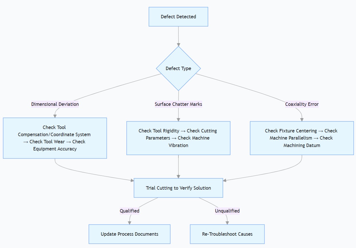
Appendix 3 Simplified Flow Chart for Common Defect Troubleshooting
Disclaimer
- All information, opinions, and data contained in this article are for the purpose of information transmission only and do not constitute any advice on investment, transactions, law, medical care, or other matters.
- The content of the article is compiled based on public information or created based on the author’s personal understanding. Although every effort is made to ensure accuracy, it does not guarantee the completeness, accuracy, and timeliness of the information, nor does it bear any responsibility for any losses caused by the use of the content of this article.
- If the article involves third-party opinions, pictures, data, and other content, the copyright belongs to the original author. In case of infringement, please contact us for deletion.
- Readers should make independent decisions based on their actual situation and combined with professional opinions. The user shall bear all consequences arising from the use of the content of this article.

Name: Dr. Benjamin Keller
Nationality: Germany
Titles: Senior Research Scientist, Industrial Technology Consultant
Work Experience and Industry Qualifications:
An expert in the CNC field from Germany, with 25 years of in – depth industry experience. He has long focused on the high – precision optimization of five – axis linkage machining technology, the intelligent upgrade of AI – driven numerical control systems, and the practical application of digital twins in machining scenarios. He is particularly good at solving machining technical problems of complex surfaces in aerospace and precision components in the medical field. He is proficient in advanced programming of G – code and M – code, and is skilled in the debugging and optimization of mainstream numerical control systems such as Fanuc and Siemens. He can build an adaptive model of cutting parameters through machine learning algorithms, use virtual simulation tools to pre – rehearse the machining process and perform error compensation. At the same time, he has the ability to integrate multi – axis machining processes and additive manufacturing technologies, which can effectively improve machining efficiency and precision consistency.