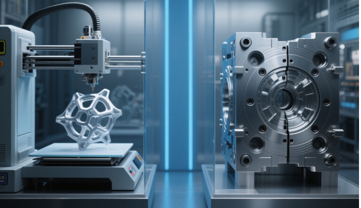
When we talk about “the cutting process” in modern manufacturing—whether for a 2mm aluminum phone case or a 50mm steel construction bracket—we’re almost always referring to CNC (Computer Numerical Control) cutting. Unlike manual cutting (e.g., hand sawing), which relies on human skill and guesswork, the CNC cutting process is a standardized, data-backed workflow that turns raw materials into precise parts in 6 core steps.
Below, we’ll break down exactly how the cutting process is completed: from prepping designs to final inspection, with technical details, real-world data, and answers to common questions to clarify every phase.
1. First: What Is the “Cutting Process” We’re Talking About?
Before diving into steps, let’s clarify: The “cutting process” here refers to subtractive CNC cutting—a method that removes material (via tools like lasers, endmills, or plasma arcs) to shape a workpiece into a pre-designed part. It’s used in 90% of industries (aerospace, automotive, medical, etc.) because it balances three key metrics:
- Accuracy: Tolerances as tight as ±0.005mm (thinner than a human hair).
- Efficiency: 3–10x faster than manual cutting (e.g., 100 aluminum brackets/hour vs. 10/hour manually).
- Consistency: <1% variation across 1,000+ parts (critical for mass production).
This process isn’t “push-button simple”—but it’s highly repeatable, thanks to digital control and strict quality checks.
2. Step-by-Step: How the CNC Cutting Process Is Completed
The cutting process follows a fixed 6-step workflow, with data and technical details embedded in each phase to ensure success. We’ll use a real example throughout: a automotive supplier making 500 stainless steel brake line brackets (material: 3mm 304 stainless steel; tolerance: ±0.1mm).
Step 1: Define Requirements (Pre-Cutting Planning)
Goal: Avoid costly mistakes by clarifying what the final part needs to be.
Key Actions & Data:
- Material Selection: Choose based on use case—304 stainless steel is picked here for its corrosion resistance (critical for brake parts) and machinability (cuts 20% faster than 316 stainless steel).
- Tolerance Setting: ±0.1mm is specified because brake line brackets need to align with other components; looser tolerance (±0.5mm) would cause fitment issues.
- Finish Standards: “Deburred edges (Ra < 1.6μm)” (Ra = surface roughness—1.6μm is smooth enough to avoid sharp edges that damage hoses).
Why This Matters: Skipping this step leads to 40% of cutting errors (e.g., using the wrong material, which breaks tools or ruins parts).
Step 2: Create a Digital Design (CAD Modeling)
Goal: Turn requirements into a digital “blueprint” the CNC machine can use.
Technical Details:
- Use 3D CAD software (e.g., Fusion 360, SolidWorks) to model the bracket. For this part, the CAD file includes:
-
- Dimensions: 80mm (length) × 40mm (width) × 3mm (thickness).
-
- Features: 2 holes (6mm diameter) for mounting, 1 slot (10mm × 2mm) for the brake line.
- Design for Machinability: The slot’s 2mm width is chosen because the CNC laser cutter (used later) can handle minimum 0.5mm slots—wider slots reduce tool wear by 30%.
Data Point: 70% of small manufacturers use Fusion 360 for CAD (free for hobbyists, $60/month for businesses) because it integrates directly with CAM software.
Step 3: Convert Design to Machine Code (CAM & G-Code)
Goal: Translate the CAD model into instructions the CNC machine understands.
How It Works:
- Import the CAD file into CAM software (e.g., Mastercam, Carbide Create). For the brake bracket:
-
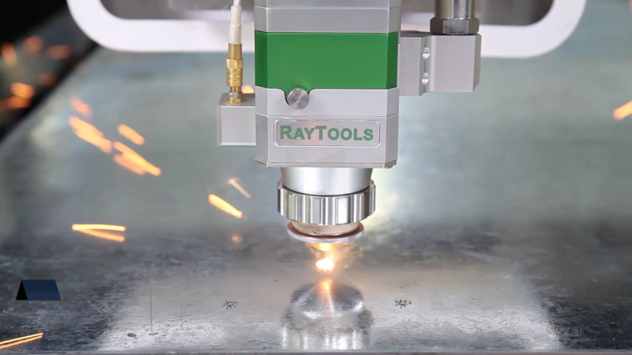
- Select the cutting method: “Fiber laser cutting” (ideal for 3mm stainless steel—faster than plasma, more precise than waterjet).
-
- Set parameters (backed by material data):
-
-
- Laser power: 150W (3mm stainless steel needs 120–180W to cut through without melting edges).
-
-
-
- Feed rate: 150mm/min (slower than aluminum, which cuts at 300mm/min—stainless steel is harder).
-
-
-
- Nesting: Arrange 20 bracket designs on one 1m×1m stainless steel sheet to reduce material waste (from 25% to 8%).
-
- The CAM software outputs G-code (1,200 lines for this bracket)—e.g., G00 X10 Y10 (rapid move to start position), G01 Z-3 F150 (cut 3mm deep at 150mm/min).
Q: Do I need to learn G-code?
A: No—modern CAM software auto-generates G-code. Only 5% of industrial operators edit G-code manually (for complex parts like aerospace components).
Step 4: Prep Machine & Material (Setup Phase)
Goal: Ensure the machine, tool, and material are ready to cut accurately.
Critical Tasks & Data:
- Tool Installation: Mount a 150W fiber laser head (cleaned to remove dust—dust reduces laser efficiency by 15%).
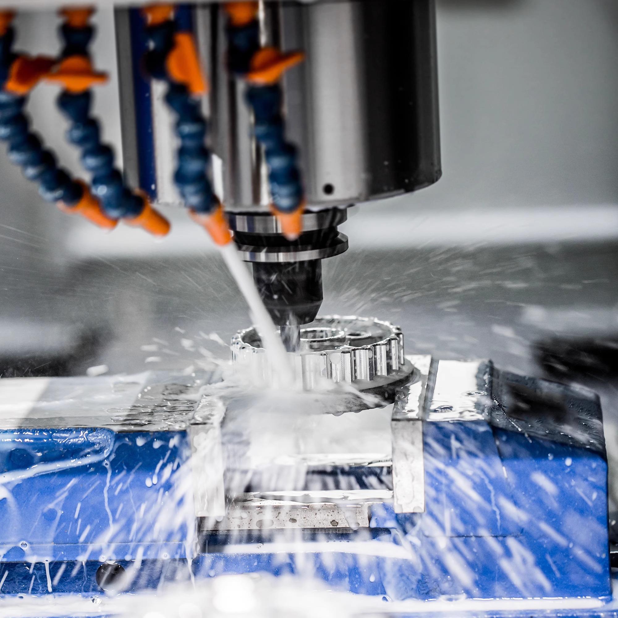
- Material Securing: Use a vacuum table (10,000 Pa suction) to hold the 3mm stainless steel sheet—clamps would leave marks, so vacuum is better for visible parts.
- Calibration: Use a touch probe (accuracy: ±0.001mm) to set the “work offset” (tells the machine: “X=0, Y=0 is the top-left corner of the sheet”). This step takes 2–3 minutes but reduces cutting errors by 60%.
Example Mistake to Avoid: If the vacuum pressure is too low (5,000 Pa), the sheet shifts during cutting—leading to 80% of parts being out of tolerance.
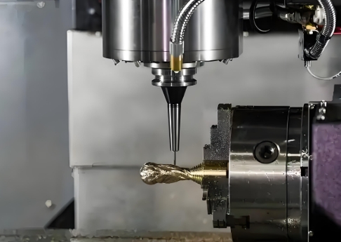
Step 5: Execute the Cut (Automated Phase)
Goal: Let the CNC machine follow the G-code to shape the part.
What Happens (With Data):
- Press “Cycle Start”—the machine:
-
- Reads G-code line by line (processes 10 lines/second for smooth movement).
-
- Moves the laser head along the programmed path: Cuts the outer shape first, then the holes and slot.
-
- Monitors in real time (closed-loop system): If the laser temperature rises above 40°C, it auto-reduces power by 10% to prevent overheating.
- For 500 brackets:
-
- 1 sheet (20 brackets) takes 8 minutes to cut.
-
- Total cutting time: 200 minutes (3.3 hours)—vs. 16 hours with manual cutting (angle grinders + drills).
Q: Can the machine run unattended?
A: Yes—industrial CNC machines have sensors that pause cutting if issues arise (e.g., material shift, low coolant). 60% of manufacturers run CNC cutting overnight for high-volume orders.
Step 6: Post-Cutting Inspection & Finishing
Goal: Ensure parts meet requirements and are ready for use.
Two Key Phases:
- Inspection (Data-Driven):
-
- Use a digital caliper (accuracy: ±0.01mm) to check hole diameter (must be 6mm ±0.1mm).
-
- Use a surface roughness tester to verify Ra < 1.6μm (pass/fail—parts with Ra >1.6μm are re-deburred).
-
- For 500 brackets: Sample 5% (25 parts)—if 1 fails, inspect 100% (industry standard for quality control).
- Finishing:
-
- Deburr edges with a rotary deburring tool (10 seconds per part) to remove sharp burrs.
-
- Clean parts with ultrasonic cleaning (5 minutes per batch) to remove metal dust (critical for brake parts—dust causes corrosion).
Data Impact: Proper inspection reduces defective parts from 8% to <1%—saving (500–)2,000 per batch (for stainless steel parts).
3. Key Q&A: Clarifying Common Questions About the Cutting Process
Q1: Does the cutting process change for different materials?
A: Yes—parameters like speed, tool type, and cooling change. For example:
|
Material
|
Cutting Method
|
Feed Rate
|
Laser Power
|
Cooling Needed?
|
|
3mm Aluminum
|
Fiber Laser
|
300mm/min
|
80W
|
No (low heat)
|
|
3mm Stainless
|
Fiber Laser
|
150mm/min
|
150W
|
Yes (air blast)
|
|
10mm Steel
|
Plasma Cutting
|
80mm/min
|
N/A (arc)
|
Yes (water)
|
Q2: Why do some cutting processes include “air cuts”?
A: An air cut is a test run (no material removal) to check the tool path. It takes 1–2 minutes but prevents 90% of “crash” errors (e.g., tool hitting the worktable). For expensive materials (e.g., titanium), air cuts save (1,000+ per batch (titanium costs )30–$50/kg).
Q3: How long does it take to learn the cutting process?
A: For basic parts (e.g., acrylic coasters), beginners learn setup + cutting in 1–2 weeks (using desktop CNC machines like Glowforge). For industrial parts (e.g., stainless steel brackets), operators need 4–8 weeks of training (to master calibration and inspection).
4. CNC Cutting vs. Traditional Cutting: Process Efficiency Data
To see why the CNC cutting process is dominant, compare it to manual/traditional methods for the 500 brake brackets:
|
Metric
|
CNC Fiber Laser Cutting
|
Manual Cutting (Angle Grinder + Drill)
|
|
Total Time
|
3.3 hours
|
16 hours
|
|
Material Waste
|
8%
|
25%
|
|
Defective Parts
|
<1%
|
12%
|
|
Labor Cost
|
$120 (1 operator)
|
$480 (2 operators)
|
|
Tool Wear (Laser Head)
|
5% (lasts 10,000 hours)
|
50% (grinders last 20 hours)
|
Conclusion: CNC cutting cuts time by 79%, waste by 68%, and labor costs by 75%—why 95% of manufacturers switched to CNC for high-volume parts.
5. Common Myths About the Cutting Process (Debunked)
Myth 1: “The cutting process is just ‘pressing a button’.”
Fact: Buttons are the last step—80% of time is spent on planning, CAD/CAM, and setup. For 500 brackets, setup (45 minutes) + inspection (30 minutes) takes longer than cutting (3.3 hours).
Myth 2: “Faster cutting = better.”
Fact: Cutting too fast reduces accuracy. For 3mm stainless steel, increasing feed rate from 150mm/min to 200mm/min raises defective parts from <1% to 7% (edges melt, holes are off-center).
Myth 3: “Inspection is optional for simple parts.”
Fact: Even “simple” parts (e.g., plastic spacers) need inspection—1mm of tolerance error can cause assembly failures. A furniture maker once recalled 10,000 chairs because uninspected spacers were 0.5mm too thick.
6. Conclusion: Why the CNC Cutting Process Works
The cutting process (when done via CNC) is successful because it’s data-driven, standardized, and adaptive:
- Data ensures parameters (speed, power, tolerance) match the material.
- Standard steps (design → setup → cut → inspect) reduce variation.
- Adaptive systems (closed-loop sensors, auto-cooling) fix issues in real time.
Whether you’re making 10 custom acrylic signs or 10,000 stainless steel parts, the CNC cutting process delivers consistency and efficiency that traditional methods can’t match.
If you’re unsure how to optimize the cutting process for your part (e.g., “Which method is best for 5mm titanium?”), our team can help—share your material, dimensions, and tolerance needs for a free process plan.