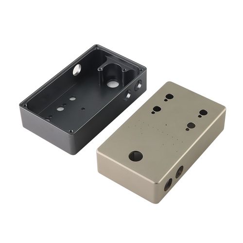
CNC machining aluminum parts involves a structured process leveraging aluminum’s machinability: start with selecting the right alloy (e.g., 6061, 7075), design using CAD/CAM software, set up the workpiece with secure fixturing, and machine with carbide tools at high speeds. Key steps include roughing to remove bulk material, finishing for precision, and cooling to prevent heat damage. Post-processing (deburring, anodizing) enhances quality, ensuring parts meet functional and aesthetic needs.
Detailed Guide to CNC Machining Aluminum Parts
1. Material Selection: Choosing the Right Aluminum Alloy
Aluminum’s machinability varies by alloy, dictating tooling and parameters:
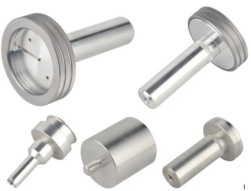
- 6061 Aluminum: The most popular choice for CNC machining. It offers excellent balance of strength (tensile strength ~310 MPa), ductility, and machinability, making it ideal for prototypes, brackets, and consumer goods. Its low silicon content reduces tool wear.
- 7075 Aluminum: A high-strength alloy (tensile strength ~570 MPa) used for load-bearing parts (aerospace components, automotive parts). Harder than 6061, it requires slower feeds and coated tools to avoid excessive wear.
- 3003 Aluminum: A softer, more ductile alloy (tensile strength ~110 MPa) suited for decorative parts or thin-walled components (e.g., heat sinks). It machines quickly but may deform under high pressure, requiring careful fixturing.
- 5052 Aluminum: Corrosion-resistant with moderate strength, used for marine or outdoor parts (e.g., boat fittings). Its good formability works well for complex shapes with tight radii.
Alloys are typically supplied as sheets, bars, or billets; cut blanks to near-net shape first to reduce machining time.
2. Design & Programming: CAD/CAM for Aluminum
Precise design ensures efficient machining:
- CAD Design: Use software like SolidWorks or Fusion 360 to model parts, incorporating Design for Manufacturability (DFM) principles. Avoid sharp internal corners (use ≥0.5mm radii) to match standard tool sizes, and limit deep slots (depth <5× width) to prevent tool deflection.
- CAM Programming: Convert CAD models to toolpaths with CAM software (Mastercam, GibbsCAM). Optimize parameters for aluminum:
- Roughing: Use large end mills (10–20mm) with high feed rates to remove bulk material quickly.
- Finishing: Employ smaller tools (3–6mm) and slower feeds for smooth surfaces (Ra <1.6μm).
- Toolpaths: Use climb milling (tool rotates with the feed direction) to reduce chatter and improve surface finish in aluminum.
3. Setup: Fixturing & Tooling Preparation
Proper setup prevents workpiece movement and tool damage:
-
Workpiece Fixturing:
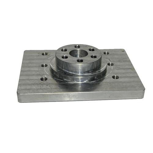
- For small parts: Use a precision vise with soft jaws (coated in rubber or aluminum) to avoid marring surfaces.
- For large/flat parts: Vacuum chucks or magnetic tables provide uniform clamping, critical for thin sheets (≤2mm) prone to warping.
- For irregular shapes: Custom fixtures or 3D-printed jaws ensure secure gripping without distortion.
-
Tooling Selection:
- Cutting Tools: Carbide end mills are mandatory for aluminum—high-speed steel (HSS) wears too quickly. Coatings like TiAlN or ZrN reduce friction and prevent built-up edge (BUE), a common issue where aluminum adheres to the tool.
- Tool Geometry: Use tools with high helix angles (35–45°) to improve chip evacuation, and sharp cutting edges to minimize material tearing. Ball-nose mills work for 3D contours; square-end mills for flat surfaces.
- Tool Length Compensation: Calibrate tool lengths with a tool setter to ensure accurate Z-axis positioning, critical for depth control in holes or slots.
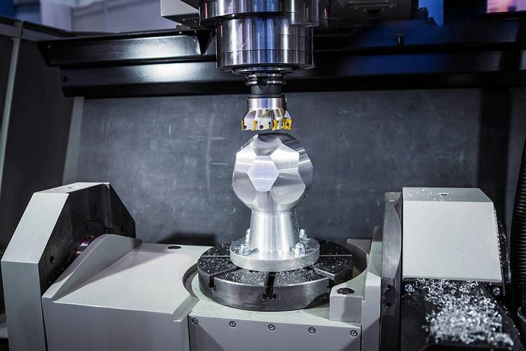
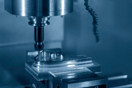
4. Machining Process: Parameters & Operations
Aluminum’s low melting point (660°C) and high thermal conductivity require careful parameter control:
-
Cutting Parameters:
- Spindle Speed: High speeds reduce heat buildup. For 6061 aluminum, use 10,000–15,000 RPM for 10mm carbide end mills; increase to 15,000–20,000 RPM for smaller tools (3–6mm).
- Feed Rate: 1000–2000 mm/min for roughing (removing 2–5mm per pass); 500–1000 mm/min for finishing (0.1–0.3mm passes) to ensure surface quality.
- Depth of Cut: For roughing, use 2–3× tool diameter (e.g., 20mm depth for a 10mm tool); finishing uses 0.1–0.5mm depths.
-
Key Operations:
- Roughing: Remove 70–80% of excess material with aggressive feeds to save time. Use flood cooling to flush chips and cool the tool.
- Finishing: Focus on precision—use slower feeds and climb milling to achieve tight tolerances (±0.01mm) for mating surfaces (e.g., holes for fasteners).
- Drilling & Tapping: Use carbide drills with coolant-through holes to prevent overheating. For threads, use spiral-flute taps at 500–1000 RPM, with cutting oil to reduce friction.
5. Cooling & Chip Management
Aluminum chips are soft and can clog tools or recut, causing defects:
- Coolant Systems: Use water-soluble coolant (5–10% concentration) to dissipate heat and lubricate the cutting zone. High-pressure coolant (30–50 bar) improves chip evacuation in deep slots or holes, preventing BUE.
- Chip Removal: Ensure clear toolpaths with adequate space for chips to exit. Use chip breakers on tools or program pauses to clear chips manually for intricate parts. Avoid dry machining—heat can warp aluminum or melt the tool coating.
6. Post-Processing & Quality Inspection
Final steps enhance functionality and appearance:
-
Deburring: Remove sharp edges with nylon brushes, deburring tools, or tumbling to prevent injury and improve fit during assembly. Critical for parts like hand tools or consumer electronics.
-
Surface Treatment:
- Anodizing: Creates a hard, corrosion-resistant oxide layer (ideal for outdoor or wear-prone parts like bike frames).
- Polishing: Achieve mirror finishes (Ra <0.05μm) for decorative parts using 600–1200 grit sandpaper followed by buffing.
- Painting/Powder Coating: Adds color and protection for aesthetic parts (e.g., automotive trim).
-
Inspection: Use calipers, micrometers, or CMMs to verify dimensions. Check surface finish with a profilometer and ensure threads fit with gauges (e.g., 6g/6H for metric threads).
7. Common Challenges & Solutions
Aluminum machining has unique issues, addressed with targeted fixes:
- Built-Up Edge (BUE): Aluminum adheres to the tool, causing poor surface finish. Solution: Increase spindle speed, use coated carbide tools, or apply cutting oil to reduce friction.
- Chatter (Vibration): Causes wavy surfaces, especially in thin walls. Solution: Shorten tool overhang (≤3× tool diameter), use rigid 刀柄 (tool holders), or reduce feed rate.
- Warping: Thin parts distort under clamping pressure. Solution: Use vacuum chucks for uniform hold, or machine in multiple light passes instead of deep cuts.
- Tool Wear: High speeds can wear tools quickly in 7075 aluminum. Solution: Use TiAlN-coated carbide tools and reduce feed rate by 10–20% compared to 6061.
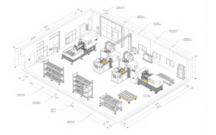
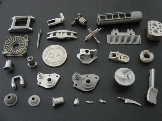
8. Industry Applications
CNC aluminum parts serve diverse sectors:
- Aerospace: 7075 aluminum brackets and frames machined to ±0.005mm tolerances for weight and strength.
- Automotive: 6061 aluminum heat sinks and intake manifolds, requiring efficient cooling during machining.
- Consumer Electronics: Thin-walled 6061 enclosures for laptops/smartphones, finished with anodizing for scratch resistance.
- Medical Devices: 5052 aluminum components for MRI equipment, valued for corrosion resistance and non-magnetic properties.
By combining alloy-specific parameters, proper tooling, and careful cooling, CNC machining aluminum produces high-quality parts efficiently. Its adaptability across industries—from prototypes to mass production—makes it a cornerstone of modern manufacturing.