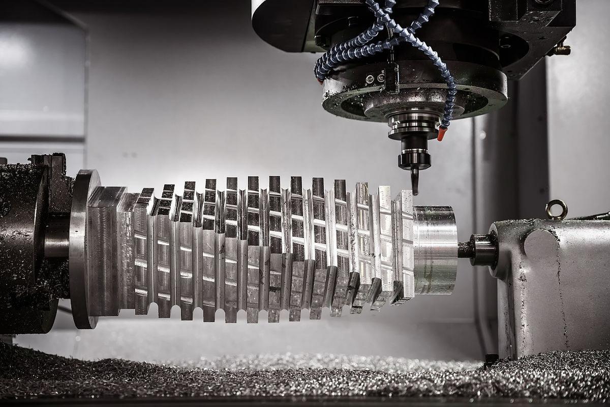
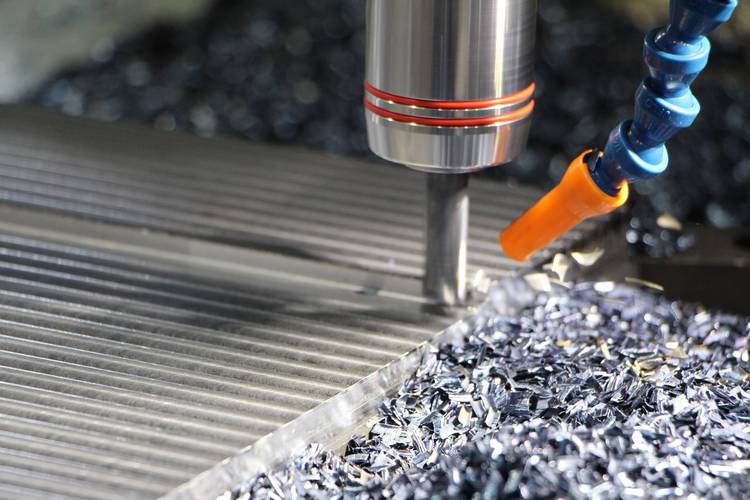
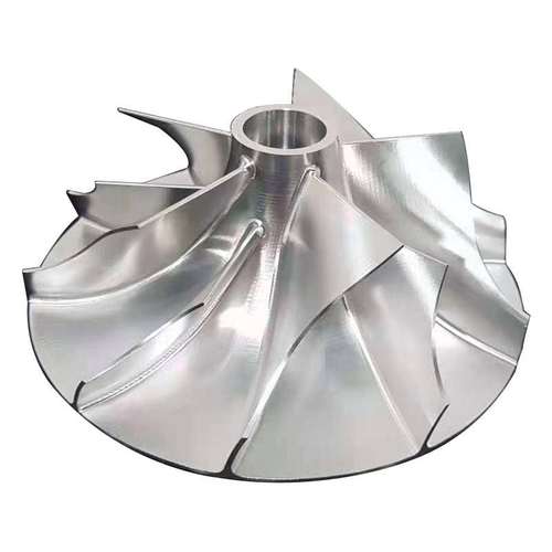
CNC machining of turbine blades relies on 5-axis synchronization to shape complex aerodynamic profiles, thin walls, and twisted geometries. Using high-speed cutting (HSC) with specialized tools, it processes tough materials like nickel-based superalloys or titanium alloys. Precision steps include roughing, semi-finishing, and finishing, with in-process inspection to meet tight tolerances (±0.02mm), critical for aerodynamic efficiency and structural integrity.
Detailed Analysis of CNC Machining Turbine Blades
1. Core Technologies
Turbine blades’ intricate designs demand advanced CNC technologies to balance precision and material toughness:
-
5-Axis Machining Centers: These systems (3 linear + 2 rotational axes) enable simultaneous tool movement along complex contours, essential for machining twisted airfoils, leading/trailing edges (as thin as 0.5mm), and root fillets. Continuous 5-axis interpolation ensures the cutter maintains optimal contact with the blade surface, reducing tool paths by 30–50% compared to 3-axis machines.
-
High-Speed Cutting (HSC): Operating at 10,000–40,000 RPM, HSC minimizes cutting forces and heat buildup—critical for nickel-based alloys (e.g., Inconel 718) and titanium (Ti-6Al-4V). Lower forces reduce workpiece deflection (vital for thin walls), while faster chip evacuation prevents recutting and tool wear.
-
Adaptive Machining: Sensors integrated into the CNC system adjust tool paths in real time based on material variations (e.g., forging inconsistencies). This compensates for 3–5% dimensional deviations in raw blanks, ensuring final part accuracy.
-
Tooling Solutions:
- Carbide End Mills: Coated with TiAlN or AlCrN, these handle titanium alloys, offering 2–3x longer life than uncoated tools.
- Ceramic or CBN Tools: For nickel-based superalloys, these withstand 1,000°C+ cutting temperatures, reducing cycle times by 40% vs. carbide.
- Contour-Matched Cutters: Ball-nose or barrel cutters with large radii (10–20mm) machine blade surfaces in fewer passes, improving surface finish (Ra <0.8μm).
2. Machining Process
Turbine blade CNC machining follows a structured workflow to balance material removal and precision:
-
Blank Preparation:
- Blades start as forged or cast blanks (near-net-shape to minimize machining). Forged blanks (used in high-stress applications) have tighter grain structures but require more material removal; cast blanks (e.g., investment-cast turbine blades) have pre-formed airfoils, reducing CNC time by 20–30%.
- Blanks undergo pre-machining inspection via 3D scanning to map deviations from CAD models, guiding adaptive tool paths.
-
Roughing:
- Large stock removal (60–80% of blank weight) using face mills or roughing end mills. For titanium, cutting speed is 50–100 m/min with high feed rates (0.1–0.3 mm/tooth) to avoid work hardening.
- Focus on removing bulk material from the blade root, platform, and trailing edge, leaving 1–2mm (stock) for finishing.
-
Semi-Finishing:
- Machines the airfoil contour to within 0.1–0.2mm of final dimensions using 5-axis ball-nose mills. For twisted blades, the CNC interpolates tool angles to follow the 3D profile, ensuring uniform stock removal.
- Coolant systems (high-pressure oil mist or flood cooling) prevent heat-induced distortion—critical for Inconel 718, which retains heat and can warp if overheated.
-
Finishing:
- Achieves final aerodynamic geometry with tolerances of ±0.02mm. Small-diameter end mills (3–6mm) machine leading edges (sharp radii <0.5mm) and fillets (R0.3–0.5mm) between the airfoil and platform.
- Surface finish is refined to Ra 0.4–0.8μm using low-feed, high-speed passes (15,000–25,000 RPM) to meet aerodynamic efficiency requirements.
-
Post-Processing & Inspection:
- Deburring: Removes micro-burrs from edges using abrasive flow machining or robotic brushing to prevent stress concentration.
- Metrology: Coordinate Measuring Machines (CMMs) or optical scanners verify compliance with CAD models, checking parameters like chord length, twist angle, and wall thickness.
3. Materials & Machining Challenges
Turbine blades use high-performance materials, each with unique machining demands:
-
Titanium Alloys (Ti-6Al-4V): Lightweight (4.43 g/cm³) and strong at 300–400°C (used in low-pressure turbine blades). Challenges include low thermal conductivity (causing heat buildup at the tool tip) and reactivity with cutting tools at high temperatures. Solutions: Use sharp carbide tools with TiAlN coatings, low cutting speeds (60–100 m/min), and flood cooling.
-
Nickel-Based Superalloys (Inconel 718, CMSX-4): Withstand 600–1,000°C (ideal for high-pressure turbine blades). Their high hardness (35–45 HRC) and work-hardening tendency accelerate tool wear. Solutions: Ceramic tools (Al₂O₃ or Si₃N₄) at 200–300 m/min, paired with rigid machine spindles to avoid vibration.
-
Ceramic Matrix Composites (CMCs): Silicon carbide (SiC) CMCs tolerate 1,200°C+ (used in next-gen). Machining them requires diamond-impregnated tools or electrical discharge machining (EDM), as they are brittle and abrasive.
4. Types of Turbine Blades & Applications
CNC machining adapts to diverse blade designs across industries:
-
Aerospace Turbine Blades:
- High-Pressure (HP) Blades: Small (50–150mm), thin-walled (<2mm), with extreme twist. Machined from single-crystal superalloys for creep resistance; require sub-0.01mm precision to maintain airflow.
- Low-Pressure (LP) Blades: Larger (300–600mm), longer, and lighter (titanium-based). Focus on reducing weight via thin walls (1–3mm) while avoiding vibration during machining.
-
Industrial Gas Turbine Blades:
- Used in power generation, these are larger (500–1,000mm) and thicker-walled. Machining prioritizes material removal efficiency (using high-feed roughing tools) over speed, with tolerances of ±0.05mm.
-
Automotive Turbocharger Blades:
- Small (30–80mm), mass-produced from Ti-6Al-4V or stainless steel. CNC lines with automated loading/unloading achieve cycle times <5 minutes per blade, balancing cost and precision.
5. Key Industries & Requirements
- Aerospace: Demands the strictest standards—blades must withstand 10,000+ flight cycles without fatigue. Machining focuses on weight reduction (via thin walls) and aerodynamic accuracy to maximize fuel efficiency.
- Energy (Power Generation): Gas/steam turbine blades require corrosion resistance (from moisture or combustion byproducts). CNC processes include protective coating preparation (e.g., plasma-sprayed thermal barriers).
- Automotive: Turbocharger blades prioritize cost and durability. CNC machining uses standardized tooling and high-volume workflows to meet production targets (10,000+ blades/week).
6. Challenges & Mitigations
- Thin-Wall Vibration: Blades with <2mm walls vibrate during cutting, causing chatter marks. Mitigation: Rigid fixturing (vacuum clamps or custom jaws) and dynamic feed adjustment (CNC reduces feed when vibration is detected).
- Tool Wear: Nickel alloys can reduce tool life to <30 minutes. Mitigation: Predictive maintenance (sensor-based tool wear monitoring) and modular toolholders for quick .
- Thermal Distortion: High cutting temperatures warp precision features. Mitigation: Coolant at 20–25°C, and post-machining stress relief (annealing for titanium, aging for Inconel).
In summary, CNC machining of turbine blades combines 5-axis precision, high-speed cutting, and material-specific strategies to master complex geometries and tough alloys—enabling reliable performance in aerospace, energy, and automotive applications.