If you’ve ever researched CNC machining, you’ve probably come across the term “CNC modeling” – but what does it really mean? Many people mistakenly think it’s just another word for 3D CAD design, but that’s only a small part of the story.
CNC modeling is the process of creating and optimizing digital models that can be directly used for CNC machining, including design geometry, toolpath planning, and manufacturability analysis. It’s the critical bridge between your design idea and the final machined part, and it directly impacts your project’s cost, lead time, and quality.
The Three Core Components of CNC Modeling
Unlike basic 3D modeling, CNC modeling is a multi-layered process that covers everything from initial design to final manufacturing preparation. Here’s what makes it up:
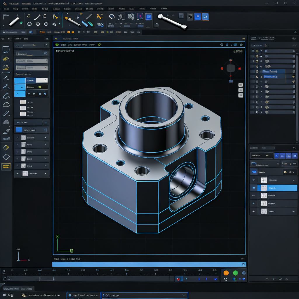
1. CAD Modeling
This is the foundation of the entire process. CAD (Computer-Aided Design) modeling involves creating the precise 3D geometry of your part, defining exact dimensions, tolerances, and material properties.
While this is similar to general 3D design, CNC-focused CAD modeling already starts considering manufacturing constraints – ensuring that the part geometry is feasible to machine before moving to the next step.
Good CAD modeling ensures that your design intent is perfectly captured in the digital model, so the machined part matches exactly what you imagined.
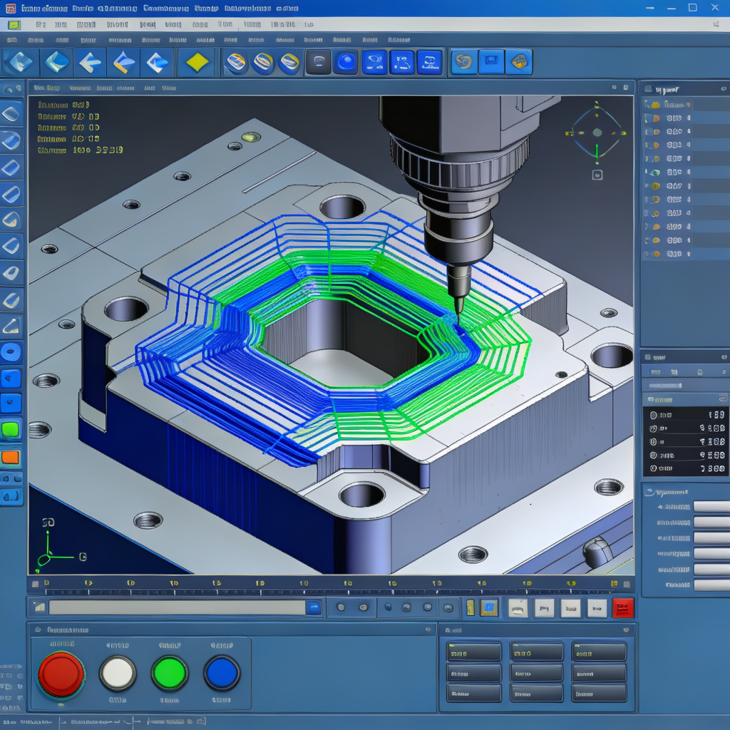
2. CAM Modeling
This is where the design turns into actionable machining instructions. CAM (Computer-Aided Manufacturing) modeling takes your CAD model and generates optimized toolpaths – the exact path that the cutting tool will follow to shape your part.
During this step, we define cutting parameters, tool selection, machining strategies (like roughing vs finishing), and ensure that the tool can reach every feature of the part without issues.
This step is what turns a static 3D model into a program that your CNC machine can actually execute, whether it’s 3-axis or 5-axis machining.
3. DFM Modeling
DFM (Design for Manufacturability) modeling is the secret sauce that most competitors ignore. This is where we analyze your model to identify potential manufacturing issues before we even start cutting metal.
We look for things like impossible-to-machine features, unnecessary tight tolerances that drive up cost, wall thickness that’s too thin or too thick, and other factors that could cause problems during machining.
By optimizing your model for manufacturability early on, we can reduce your production cost by up to 30% and cut lead time significantly, without compromising on your part’s functionality.
The CNC Modeling Workflow
Understanding the full workflow helps you see why each step matters. Here’s how we turn your idea into a machined part:
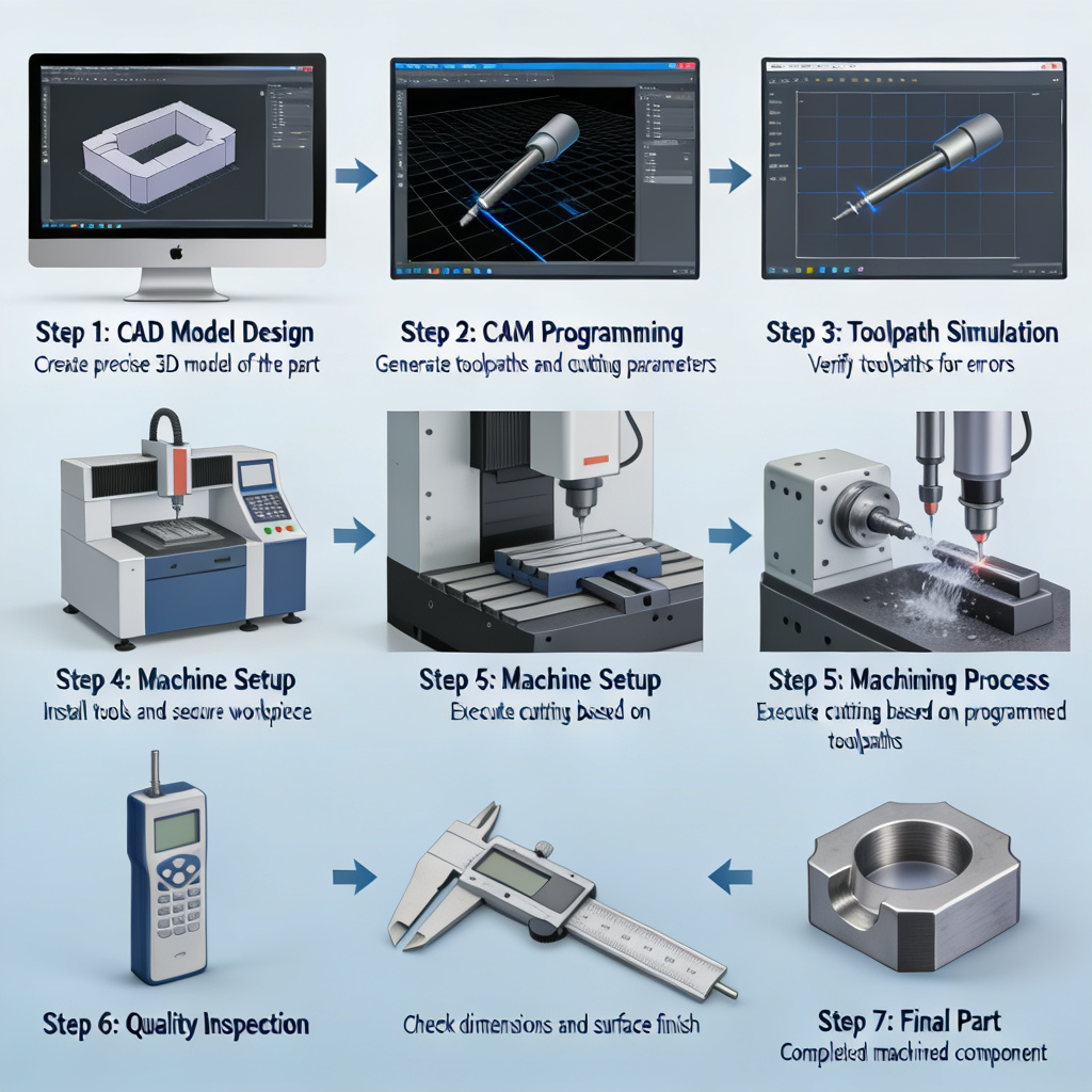
1. Create CAD Model
Build the precise 3D geometry of your part, defining all dimensions and features.
2. DFM Analysis
Analyze the model for manufacturability, identify potential issues and optimization opportunities.
3. Generate Toolpaths
Use CAM software to create optimized cutting paths for the CNC machine.
4. Simulate Machining
Run a virtual simulation to check for collisions, errors, and verify the process.
5. Output CNC Program
Convert the toolpaths into G-code, the language that CNC machines understand.
CNC Modeling vs CAD vs CNC Programming: What’s the Difference?
One of the most common sources of confusion is understanding how these terms relate to each other. They’re not the same thing – each plays a different role in the manufacturing process:
| Aspect | CNC Modeling | CAD | CNC Programming |
|---|---|---|---|
| Primary Purpose | Complete manufacturing preparation | Part design & geometry creation | Machine control instructions |
| Key Output | Manufacturing-ready optimized model | 3D part geometry model | G-code machine program |
| Business Impact | Directly affects cost & quality | Defines part structure & function | Executes the machining process |
| Scope | End-to-end: Design to machine | Design phase only | Machine control phase only |
How CNC Modeling Directly Affects Your Machining Results
You might be wondering: why does this matter so much? The truth is, CNC modeling is the single biggest factor that determines your project’s success. Here’s how:
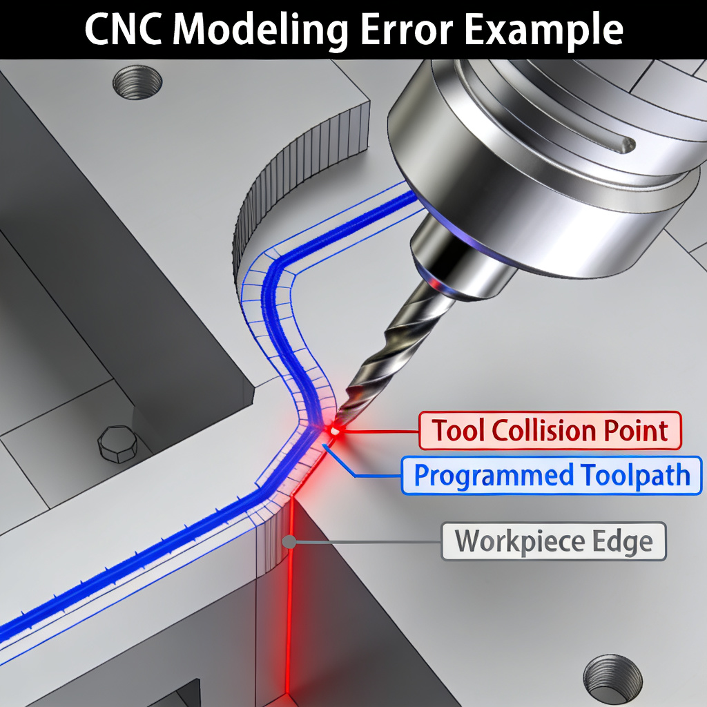
Poor Modeling → Tool Collision
Bad modeling can cause the cutting tool to crash into the workpiece or the machine itself. This doesn’t just ruin your part – it can damage expensive machine tools, leading to costly downtime and repairs.
Over-Complex Geometry → Higher Cost
Unnecessary complex features or overly tight tolerances that you don’t actually need can drive up your machining cost significantly. Good modeling helps you identify and remove these cost drivers.
Unoptimized Tolerances → Longer Lead Time
Tighter tolerances require slower, more precise machining, and often require additional inspection steps. Optimizing these during modeling can cut your lead time by days or even weeks.
The bottom line: CNC modeling directly affects your machining cost, lead time, and part quality. Get it right, and your project will be smooth, fast, and cost-effective. Get it wrong, and you could face delays, rework, and unexpected costs.
Common CNC Modeling Mistakes to Avoid
Even experienced designers can make mistakes when creating models for CNC machining. These errors might look fine on the screen, but they cause big problems during production:
- Ignoring tool radius: Forgetting that cutting tools have a radius means you can’t machine perfect sharp internal corners – this leads to unfinished features.
- Missing collision checks: Not simulating the toolpath means you might not catch tool collisions until it’s too late.
- Over-constrained models: Adding too many unnecessary constraints can make the model unstable and hard to machine.
- Unrealistic tolerances: Specifying tighter tolerances than your application actually needs, which just adds cost without benefit.
- Thin walls: Walls that are too thin can vibrate during machining, leading to poor surface finish or even part breakage.
DFM Optimization: Get Better Parts at Lower Cost
The best way to avoid these mistakes and optimize your project is to apply DFM (Design for Manufacturability) principles during the modeling phase. Here are the key tips we use with our clients:
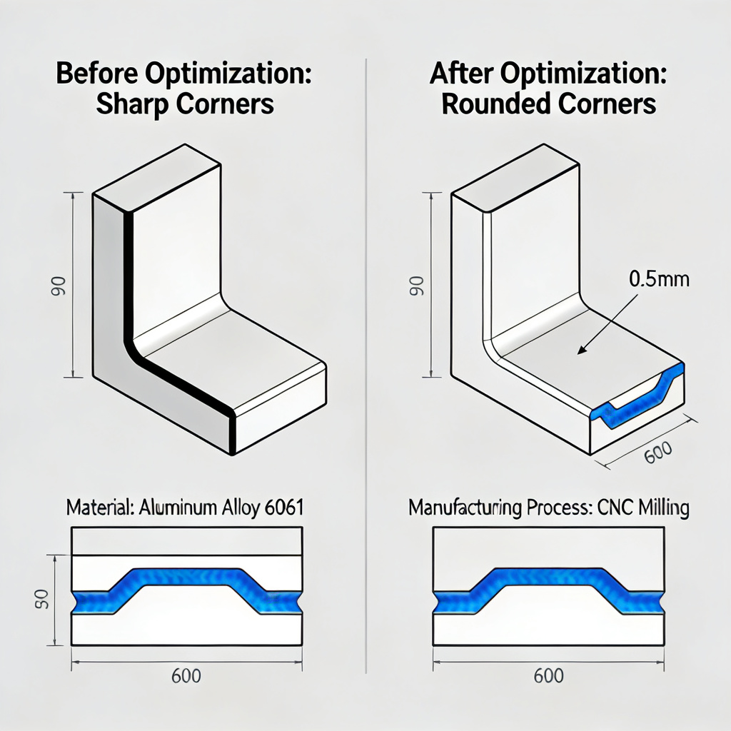
Avoid Sharp Internal Corners
Always add radius to internal corners. The minimum radius should be at least 1/3 of the cavity depth to avoid using tiny tools that slow down machining.
Reduce Unnecessary Tolerances
Only specify tight tolerances for the features that actually need them. Standard tolerances are much faster and cheaper to machine.
Optimize Wall Thickness
Keep walls at least 0.8mm for plastic and 1.5mm for metal to avoid vibration and breakage during machining.
Simplify Deep Cavities
The depth of cavities should be no more than 4x the tool diameter. Deeper than that requires special tools and slower machining.
Standardize Feature Sizes
Use standard drill sizes for holes and standard radius for corners. This lets us use standard tools, reducing cost and lead time.
Add Fillets to Edges
Adding fillets to edges not only makes the part safer to handle, it also reduces machining time and improves surface finish.
Common Applications of CNC Modeling
CNC modeling is critical across a wide range of industries and applications, wherever precision manufacturing is needed. Here are some of the most common use cases:
Prototype Development
For CNC prototyping, fast and accurate modeling lets you get functional prototypes in days, so you can test your design before full production.
Complex Multi-Axis Parts
For parts that require 5-axis machining, advanced modeling is essential to ensure the tool can reach all the complex features without collision.
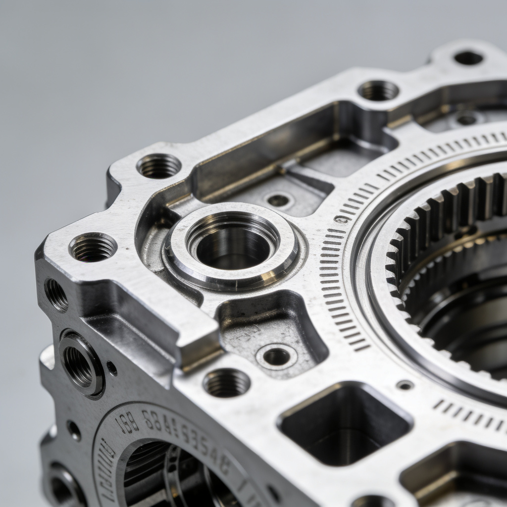
Aerospace Components
Aerospace parts require extremely high precision and strict quality standards. Detailed CNC modeling ensures every part meets the rigorous industry requirements.
Automotive & Medical Parts
From automotive engine components to medical device parts, CNC modeling ensures that critical parts are manufactured perfectly, every time.
Frequently Asked Questions
What is CNC modeling used for?
CNC modeling is used to create and optimize digital models that are ready for CNC machining. It covers everything from designing the part geometry to creating the toolpaths and checking for manufacturability, ensuring that the part can be produced accurately, efficiently, and cost-effectively.
Is CNC modeling the same as CAD?
No, they’re not the same. CAD is just the part of the process where you create the 3D geometry of the part. CNC modeling is much broader – it includes CAD, plus CAM programming, DFM analysis, and simulation to prepare the entire model for manufacturing.
How does CNC modeling affect cost?
CNC modeling has a huge impact on cost. Good modeling can identify and remove unnecessary complex features, optimize tolerances, and avoid machining errors, which can reduce your production cost by up to 30%. Bad modeling, on the other hand, can lead to rework, scrap, and machine damage, which add significant unexpected costs.
What file formats are used for CNC modeling?
The most common file formats are STEP, IGES, STL, and native CAD formats like SolidWorks, AutoCAD, or Fusion 360 files. STEP and IGES are the most universal, as they work across different software platforms and preserve the part geometry accurately.
What is the difference between CAD and CAM?
CAD (Computer-Aided Design) is used to create the 3D model of the part, defining its shape and dimensions. CAM (Computer-Aided Manufacturing) is used to take that CAD model and generate the toolpaths and machine instructions that tell the CNC machine how to cut the part. They’re two different steps in the overall CNC modeling process.
Can bad modeling ruin my CNC project?
Unfortunately, yes. Bad modeling can lead to all kinds of problems: parts that don’t fit together, surface finish issues, tolerance errors, tool collisions that damage the machine, and even complete part scrap. That’s why investing in good CNC modeling upfront is so important – it saves you from costly mistakes later.
Not Sure If Your Model Is Ready?
Our experienced engineers can review your CAD file for free, identify potential manufacturing issues, and suggest optimizations to reduce your cost and lead time.