Designing CNC parts involves balancing functionality, manufacturability, and efficiency. Start with defining requirements (function, load, environment), then use CAD software to model geometries optimized for CNC machining—avoiding unmachinable features like sharp internal corners or overly deep slots. Consider material properties, tool constraints, and tolerance limits, then validate via prototyping. This process ensures parts are precise, cost-effective, and easy to produce.
Detailed Analysis of CNC Part Design
1. Core Design Principles for Manufacturability (DFM)
Design for Manufacturability (DFM) ensures parts can be machined efficiently without unnecessary complexity or cost:
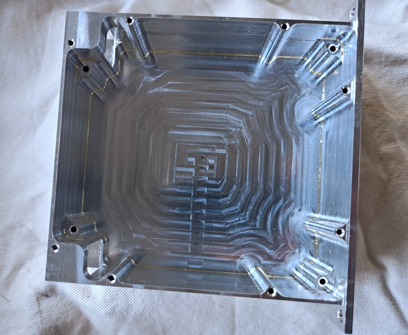
- Simplify Geometry: Avoid overcomplicating features. Sharp internal corners (<0.5mm radius) are hard to machine with standard tools; use radii ≥ tool diameter/2 (e.g., a 6mm end mill requires ≥3mm internal radii). Deep slots (depth >5× width) risk tool deflection and poor surface finish—redesign with shallower depths or split features if possible.
- Tolerance Optimization: Specify tolerances only as tight as needed. General parts work with ±0.05mm; precision components (e.g., aerospace) may need ±0.01mm, but tighter tolerances increase machining time and cost. Use geometric dimensioning and tolerancing (GD&T) to clarify critical features (e.g., hole position, flatness).
- Uniform Wall Thickness: Avoid abrupt thickness changes (e.g., 1mm to 5mm) which cause uneven cooling and stress during machining. Transition gradually over 3–5× the thickness difference to prevent warping, especially in metals like aluminum or steel.
2. Step-by-Step Design Process
A structured workflow ensures designs meet functional and manufacturing goals:
- Requirements Definition:
Outline part function (load-bearing, decorative, etc.), operating environment (temperature, corrosion), and production volume. For example, a automotive bracket must withstand 500N loads and resist road salt; a consumer electronics part prioritizes lightweight and aesthetics. - Material Selection:
Choose materials based on strength, machinability, and cost:- Aluminum 6061: Lightweight, easy to machine (ideal for prototypes, consumer goods).
- Steel 1018: Strong, cost-effective (structural brackets, machinery parts).
- Titanium Ti-6Al-4V: High strength-to-weight ratio (aerospace, medical) but harder to machine.
Material properties (hardness, thermal conductivity) influence tool selection and machining parameters.
- CAD Modeling:
Use CAD software (SolidWorks, Fusion 360) to create 3D models. Include features like:- Tool Clearance: Add 0.5–1mm gaps around features for tool access (e.g., between a boss and wall).
- Fixturing Features: Integrate tabs or holes for clamping to prevent movement during machining.
- Standard Sizes: Use common tool diameters (3mm, 6mm, 10mm) for holes/slots to reduce tool changes.
- CAM Programming & Simulation:
Export CAD models to CAM software (Mastercam, GibbsCAM) to generate toolpaths. Simulate to check for collisions (tool vs. fixture) and optimize feeds/speeds. For example, roughing uses high feed rates (1000–2000 mm/min) for aluminum; finishing uses slower rates (500–1000 mm/min) for smooth surfaces. - Prototyping & Validation:
Produce a prototype via CNC machining or 3D printing to test fit, function, and manufacturability. Measure critical dimensions with calipers or CMMs, then refine the design based on feedback (e.g., adjust wall thickness if warping occurs).
3. Material-Specific Design Considerations
Different materials demand design adjustments to maximize machinability:
-
Aluminum Alloys:
- Prone to chatter in thin sections; add ribs for rigidity.
- Anodizing-ready designs need smooth surfaces (Ra <1.6μm); avoid sharp edges that trap anodizing solution.
-
Steel & Stainless Steel:
- Harder materials require larger radii and slower feeds to reduce tool wear.
- Corrosion-resistant parts (stainless steel 304) need drainage holes to prevent coolant pooling and staining.
-
Plastics (PEEK, ABS):
- Low melting points require slower spindle speeds (3000–6000 RPM) to avoid heat damage.
- Design with generous draft angles (1–2°) for easier ejection if using injection molding post-CNC.
4. Industry-Specific Design Requirements
Designs vary by sector, driven by unique performance needs:
-
Aerospace:
Parts require high precision (±0.005mm) and lightweighting. Use thin walls (1–3mm) with internal ribs for strength; avoid unnecessary material. Titanium parts need large radii and slow machining to prevent tool breakage. -
Medical Devices:
Biocompatible materials (titanium, PEEK) are mandatory. Designs must include smooth surfaces (Ra <0.05μm) to prevent bacterial buildup and easy cleaning. Small features (e.g., 0.5mm holes in surgical tools) require micro-CNC capabilities. -
Automotive:
High-volume production demands low-cost designs with standard features (e.g., M6 holes, 10mm slots). Use readily available materials (mild steel, aluminum 6061) and minimize complex curves to reduce cycle time. -
Consumer Electronics:
Aesthetics matter—include polished surfaces and consistent radii. Lightweight designs use thin aluminum (0.5–2mm) with stiffening ribs; avoid sharp edges for user safety.
5. Common Design Mistakes & Solutions
Avoid these pitfalls to streamline production:
- Ignoring Tool Limitations: Using 0.5mm slots with a 1mm end mill causes poor finish. Solution: Match feature sizes to standard tool diameters.
- Overly Tight Tolerances: Specifying ±0.001mm for non-critical features increases cost. Solution: Reserve tight tolerances for mating surfaces (e.g., bearing fits).
- Inadequate Fixturing: Parts without clamping features shift during machining. Solution: Add temporary tabs (removed post-machining) or use existing holes for fixturing.
- Poor Chip Evacuation: Deep, narrow features trap chips, damaging tools and surfaces. Solution: Add relief slots or use through-holes to improve chip flow.
By integrating DFM principles, material knowledge, and industry requirements, CNC part designs balance functionality and manufacturability. This approach reduces production time, lowers costs, and ensures consistent quality across prototypes and mass-produced parts.