Quick Answer: What Is the Best Way to Design a Part for CNC Machining?
To design a CNC-machined part efficiently, follow these seven principles: use standard tolerances whenever possible, avoid excessively thin walls, add internal corner radii (minimum R0.5 mm), limit deep pockets to a depth-to-width ratio of 3:1, design for tool accessibility from the fewest setups, choose materials with proven machinability ratings, and specify critical tolerances only on functional surfaces — not on every dimension.
Cost impact: Proper DFM design can reduce machining costs by 20–50% and shorten lead times by 30–40% | Critical dimensions: Apply ±0.01 mm only to mating/bearing surfaces; use ±0.1 mm for non-functional features | Materials: 6061-T6 Aluminum, 304/316 Stainless Steel, Brass C360, Copper C110, POM/Delrin | Wall thickness: ≥1.0 mm (aluminum), ≥0.8 mm (steel/brass), ≥1.5 mm (plastic)
Why DFM Design Matters for CNC Parts
The difference between a part that quotes at \$85 and one that quotes at \$150 often comes down to geometry — not material, not volume, not supplier margin. Design-for-Manufacturability (DFM) is the discipline of specifying geometry, tolerances, and features that CNC tooling can efficiently produce. When procurement managers skip DFM review, the consequences show up in extended lead times, inflated quotes, and parts that fail inspection.
Poor Design Causes
- Machining costs 2–3× higher than necessary
- Lead times extended by rework cycles
- Tool breakage on thin walls and sharp corners
- Part warping from uneven material removal
- Dimensional errors from multi-setup accumulation
- Quotes rejected or marked “requires redesign”
Good DFM Design Achieves
- 20–50% cost reduction per part
- 30–40% shorter production lead time
- Higher yield rates (fewer rejected parts)
- Simplified inspection (fewer critical dimensions)
- Fewer setups = faster machining cycles
- Supplier confidence and competitive quoting
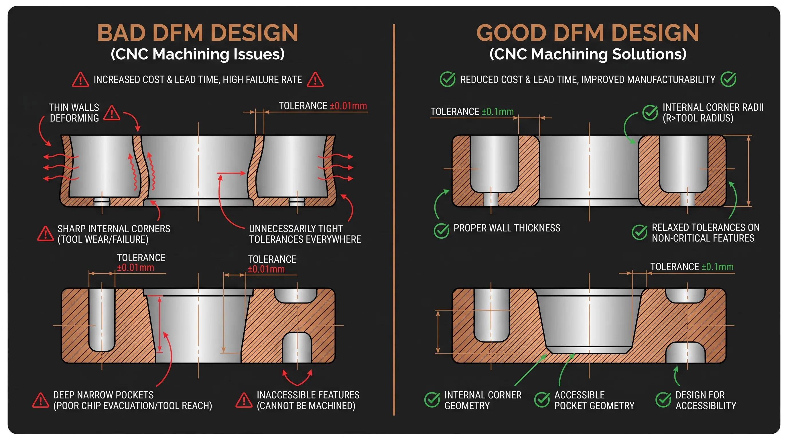
Bottom line: Every CNC machining quote is a response to your drawing. The drawing determines the cost. DFM is not an optional step — it is the primary lever procurement managers have for controlling unit price and delivery speed.
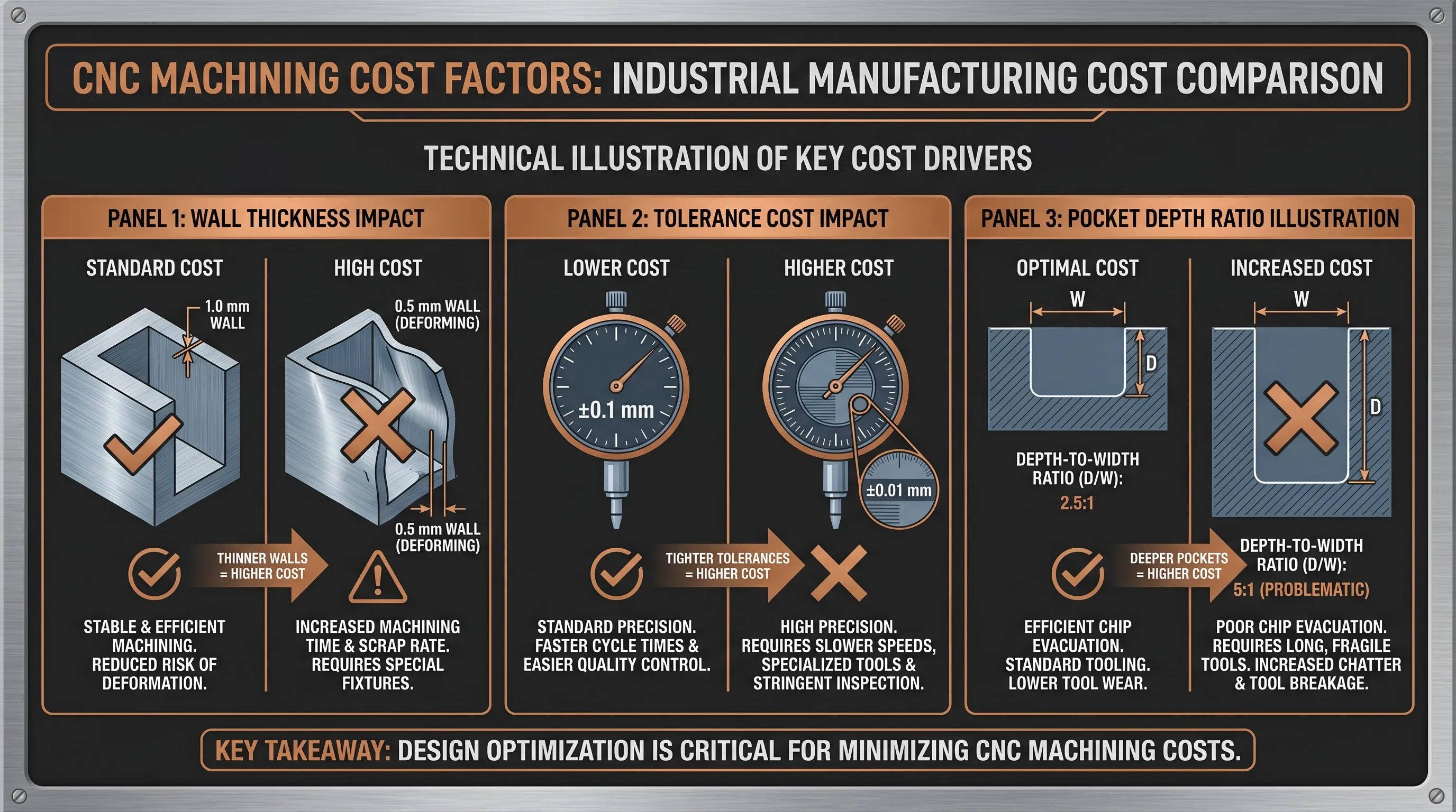
DFM Rule #1 — Wall Thickness
Thin walls are the single most common DFM violation in CNC part drawings. Walls below the recommended minimum cause chatter (tool vibration), dimensional drift during finishing passes, and in extreme cases, part deformation that makes the component unusable. The minimum wall thickness varies by material because each metal and plastic has a different stiffness and thermal expansion coefficient — which directly affects how much material the cutting tool can remove without destabilizing the workpiece.
| Material | Recommended Min. Wall | Risk Below Minimum | DFM Recommendation |
|---|---|---|---|
| Aluminum (6061/7075) | ≥1.0 mm | Chatter, wall deflection, dimensional drift | 1.2–1.5 mm preferred for structural walls; 1.0 mm acceptable for non-load-bearing ribs |
| Stainless Steel (304/316) | ≥0.8 mm | Tool wear, heat buildup, surface burn | 1.0 mm preferred; stainless retains rigidity better than aluminum at thinner sections |
| Brass (C360) | ≥0.8 mm | Burr formation, wall collapse under clamp pressure | Brass machines easily but deforms under fixturing; maintain 1.0 mm near clamp zones |
| Copper (C110) | ≥0.8 mm | Gummy cutting, tool grab, surface tearing | Copper is soft and ductile; walls under 1.0 mm prone to push-off during finishing |
| Plastic (POM/PEI) | ≥1.5 mm | Melting, warp, stress cracking | 2.0 mm preferred; plastics flex under tool pressure and lack metal’s thermal conductivity |
DFM Tip: If your drawing specifies 0.5 mm walls, expect the quote to reflect 3× the cost of a 1.2 mm wall version — or expect the supplier to flag it as “requires redesign” before quoting. Increasing wall thickness from 0.6 mm to 1.2 mm on an aluminum robotics housing reduced machining cost by 35% and scrap rate by 60% in our documented case (see Case Studies below).
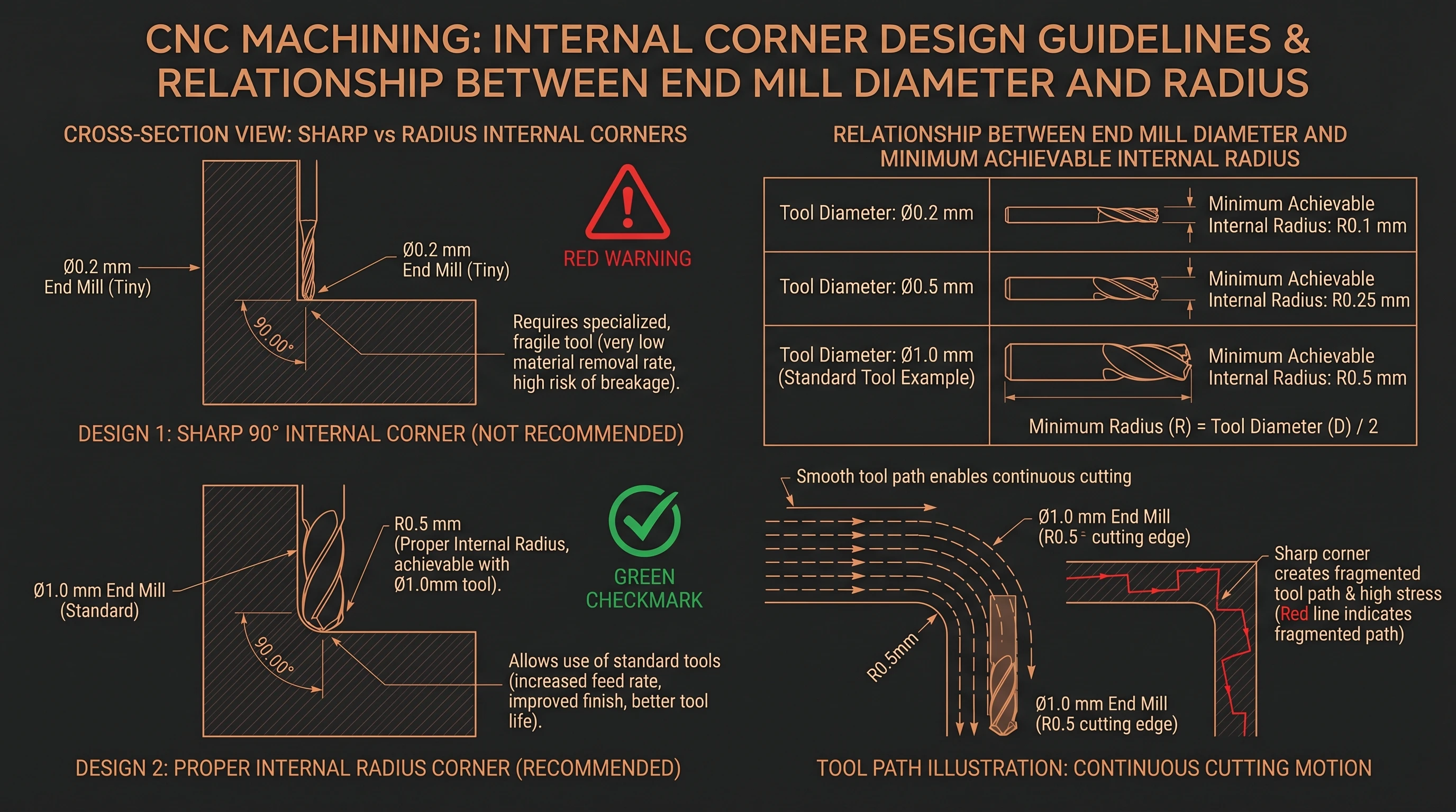
DFM Rule #2 — Internal Corner Radii
CNC end mills are cylindrical — they cannot cut a perfect 90-degree sharp internal corner. The minimum internal radius is always half the end mill diameter used to machine that pocket. When a drawing calls for sharp corners, the machinist must switch to progressively smaller tools to “clean out” the corner, which increases machining time exponentially and introduces tool breakage risk. Sharp corners also concentrate stress, reducing the part’s fatigue life under cyclic loading.
| Corner Specification | Required End Mill | Machining Impact | DFM Recommendation |
|---|---|---|---|
| Sharp corner (R0) | 0.1–0.2 mm micro tool | Multiple tool changes, 5–10× time increase, high breakage risk | Avoid entirely — add R0.5 mm minimum |
| R0.5 mm corner | 1.0 mm end mill | Single tool, standard machining | Recommended minimum for all pockets |
| R1.0 mm corner | 2.0 mm end mill | Single tool, fast cycle | Preferred for most aluminum and steel pockets |
| R2.0 mm corner | 4.0 mm end mill | Rigid tool, maximum speed | Best for large pockets and high-volume production |
Design Rule: Specify internal corner radius ≥0.5 mm on every pocket, slot, and channel in your drawing. Use R1.0 mm or larger when the pocket width exceeds 10 mm. Every sharp corner on your drawing adds a tool change and 2–5 minutes of extra machining time per pocket — across a batch of 200 parts, that translates to hours of added machine time and hundreds of dollars in cost.
DFM Rule #3 — Tolerance Specification
Over-specifying tolerances is the second most expensive DFM mistake after thin walls. When a drawing applies ±0.01 mm to every dimension — including non-functional surfaces, decorative features, and clearance holes — the machinist must slow down cutting speeds, add extra finishing passes, and inspect every dimension individually on the CMM. The cost multiplier compounds: tighter tolerances require slower feeds, more setups, additional inspection time, and higher scrap risk. The correct approach is to apply critical tolerances only to functional mating surfaces, bearing seats, and alignment features — and specify ±0.1 mm or “reference” for everything else.
| Tolerance | Typical Application | Cost Multiplier | When to Specify |
|---|---|---|---|
| ±0.1 mm | Non-critical surfaces, cosmetic features | 1× (baseline) | Default for all dimensions without functional requirements |
| ±0.05 mm | Standard CNC fit, general assembly | 1.2× | Sliding fits, locating slots, alignment pins |
| ±0.02 mm | Precision components, bearing seats | 2× | Bearing bores, shaft seats, sealing surfaces |
| ±0.01 mm | Aerospace / medical critical features | 3×+ | Only for mating interfaces where interference or clearance is functionally critical |
| Feature Type | Recommended Tolerance | Reason |
|---|---|---|
| Bearing bore (ID) | ±0.01 mm | Press-fit or line-fit requires precision for retention and alignment |
| Shaft seat (OD) | ±0.01 mm | Concentricity and runout requirements demand tight control |
| Mounting hole pattern | ±0.05 mm | Positional accuracy for assembly alignment |
| Clearance hole | ±0.1 mm | Fastener pass-through — no functional precision needed |
| Outer wall / flange | ±0.1 mm | Non-mating surface — cosmetic or structural envelope only |
| Chamfer / fillet | Reference only | Decorative or deburr feature — no tolerance needed |
Cost Rule: A part with 30 dimensions all specified at ±0.01 mm will cost 3× more than the same geometry with 4 critical features at ±0.01 mm and 26 dimensions at ±0.1 mm. In our Stainless Steel Sensor Bracket case study, selectively applying tight tolerances reduced the quote by 28%.
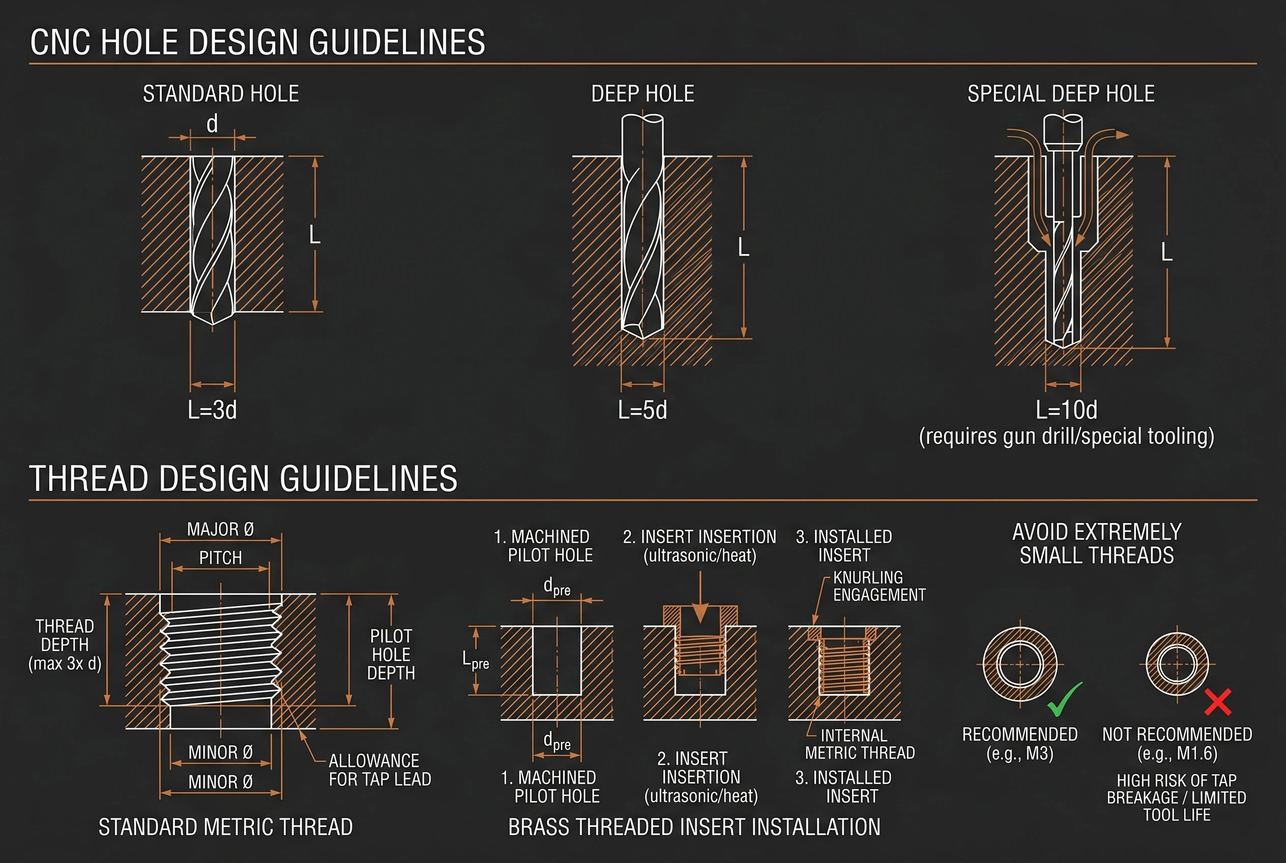
DFM Rule #4 — Hole and Thread Design
Hole depth ratio (L/D) determines tool selection, machining time, and accuracy. A standard drill can produce holes up to 3× its diameter with reliable positional accuracy and surface finish. Beyond that ratio, specialized tooling (gun drills, extended-length drills) becomes necessary, cost increases, and positional drift accumulates. Thread design follows similar logic: standard metric threads (M2–M12) are universally available and inexpensive to produce; custom thread profiles, extremely small threads (under M2), and high-load threaded features without brass inserts all add cost and risk.
| Hole Type | Depth Ratio (L/D) | Tooling Required | Cost Impact |
|---|---|---|---|
| Standard through-hole | ≤3× Diameter | Standard twist drill | Baseline — fast, accurate |
| Deep hole (blind) | 3–5× Diameter | Extended-length drill, peck cycle | 1.5× — slower cycle, peck drilling required |
| Special deep hole | >5× Diameter | Gun drill or special tooling | 2–3× — specialized process, limited suppliers |
Thread Design Guidelines
Preferred: Standard Metric
M2 through M12 standard metric threads are universally available, fast to produce, and inexpensive. Use M3, M4, M5, M6 as defaults for most assemblies.
High-Load: Use Brass Inserts
For repeated assembly/disassembly, vibration environments, or load-bearing threads in aluminum or plastic, specify helical brass threaded inserts (Helicoil style) instead of tapped threads directly in soft material.
Avoid: Extremely Small Threads
Threads below M2 (under 2 mm diameter) require micro-tapping tools that break frequently, increase cost, and deliver inconsistent thread quality. Consider press-in inserts or alternative fastening methods instead.
DFM Rule #5 — Pocket Depth and Geometry
Pocket depth-to-width ratio is the third major cost driver in CNC machining. A pocket that is 3× wider than it is deep can be machined with a single tool in one pass. As the ratio increases, the machinist must step down to progressively smaller end mills for deep corners, use peck-style clearing strategies, and add extra finishing passes to reach the floor. Deep narrow pockets also restrict tool reach, force longer tool overhangs (which cause chatter), and increase cycle time proportionally.
| Pocket Width | Recommended Max Depth | Ratio (Depth ÷ Width) | Tooling Note |
|---|---|---|---|
| 10 mm | 25 mm | 2.5:1 | 6 mm end mill, single tool |
| 20 mm | 50 mm | 2.5:1 | 12 mm end mill, standard cycle |
| 30 mm | 75 mm | 2.5:1 | 20 mm end mill, standard cycle |
| Exceeds 3:1 ratio | — | >3:1 | Requires step-down tools, chatter risk, 2×+ cost |
Core Principle: Design pocket depth ≤2.5–3× the pocket width. When your application genuinely requires deeper pockets, consider stepping the pocket width wider at the top (open-pocket design), splitting the pocket across two setups, or redesigning as a through-slot instead of a blind pocket. Every 0.5× increase beyond the 3:1 ratio adds approximately 20–30% to the machining cycle cost for that feature.
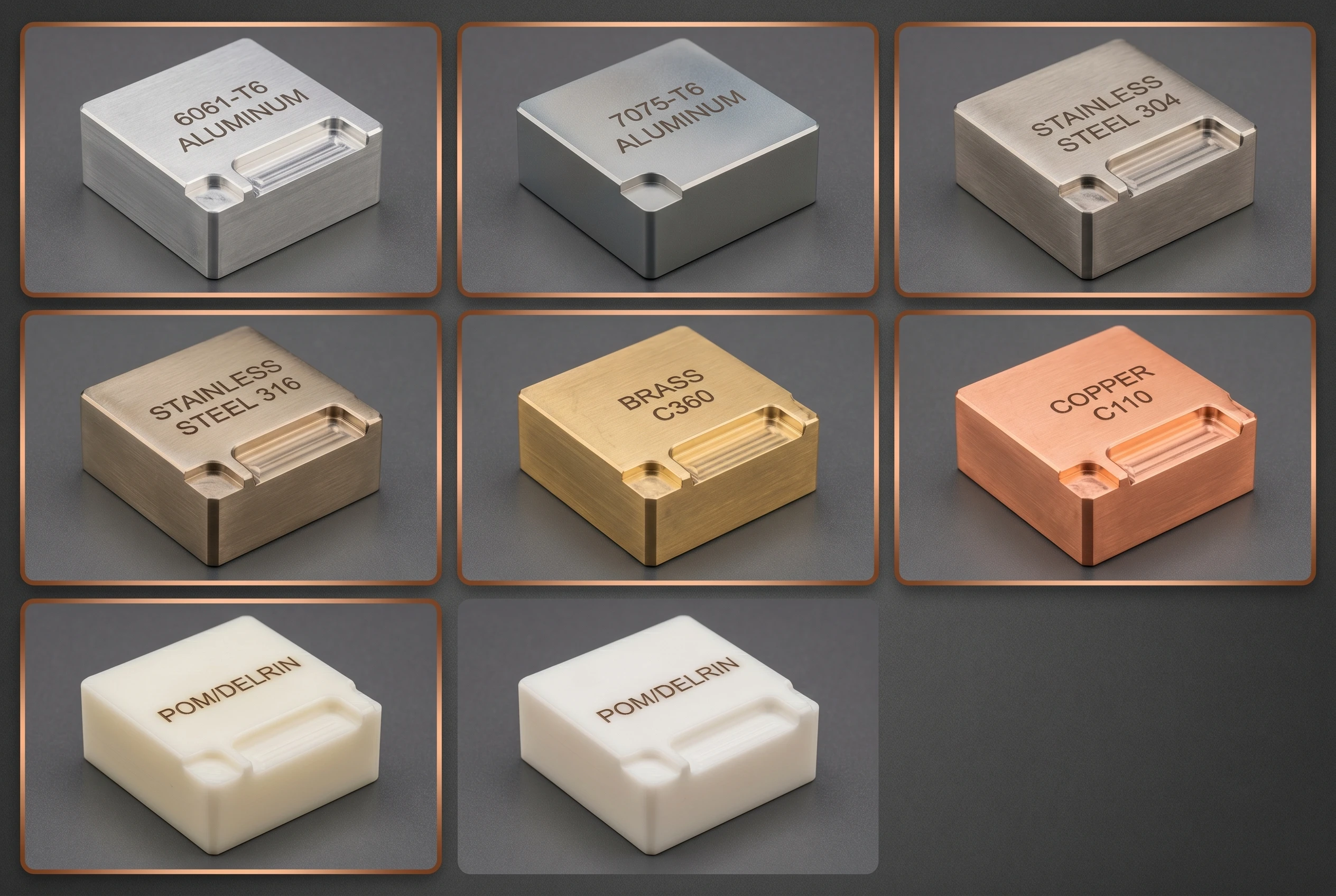
Material Selection for CNC DFM
Material choice directly determines machinability, cost per part, achievable tolerance, and surface finish quality. The machinability rating (relative to Brass C360 = 100%) is the single most useful metric for DFM cost estimation: higher machinability means faster cutting speeds, longer tool life, and lower per-part cost. Selecting a low-machinability material for a high-volume application is a DFM error that compounds across every part in the batch.
| Material | Best Application | Machinability | Min. Wall | DFM Note |
|---|---|---|---|---|
| 6061-T6 Aluminum | General-purpose, robotics, housings | Very High | ≥1.0 mm | Best cost-to-performance ratio; anodize for surface protection |
| 7075-T6 Aluminum | High-stress brackets, aerospace, e-bike | High | ≥1.0 mm | Strongest aluminum (572 MPa); 15% more machining cost than 6061 |
| Stainless 304 | Industrial, food processing, general | Medium | ≥0.8 mm | Corrosion-resistant; passivation available; moderate tool wear |
| Stainless 316 | Marine, medical, coastal equipment | Medium-Low | ≥0.8 mm | Superior corrosion resistance; slower machining speeds, higher tool cost |
| Brass C360 | Connectors, fittings, electrical | 100% (baseline) | ≥0.8 mm | Free-machining brass — fastest cutting, longest tool life, lowest cost |
| Copper C110 | Electrical, heat exchanger, bus bar | Low | ≥0.8 mm | Gummy machining behavior; requires sharp tools and low feed rates |
| POM (Delrin) | Mechanical parts, gears, low-friction | Very High | ≥1.5 mm | Excellent machinability; self-lubricating; prone to melting if feeds too slow |
Material Selection Rule: Choose the material with the highest machinability rating that meets your functional requirements. Brass and aluminum are the lowest-cost CNC materials; stainless and copper add 40–80% to machining cost per part. Select 316 only when saltwater or medical-grade corrosion resistance is required — 304 handles 90% of corrosion scenarios at lower cost.
5 Most Common CNC Design Mistakes
These five errors appear on 80% of first-time CNC drawings submitted by OEM procurement teams. Each mistake has a direct and measurable cost impact — and each is preventable with a DFM review before the drawing goes to the quoting stage.
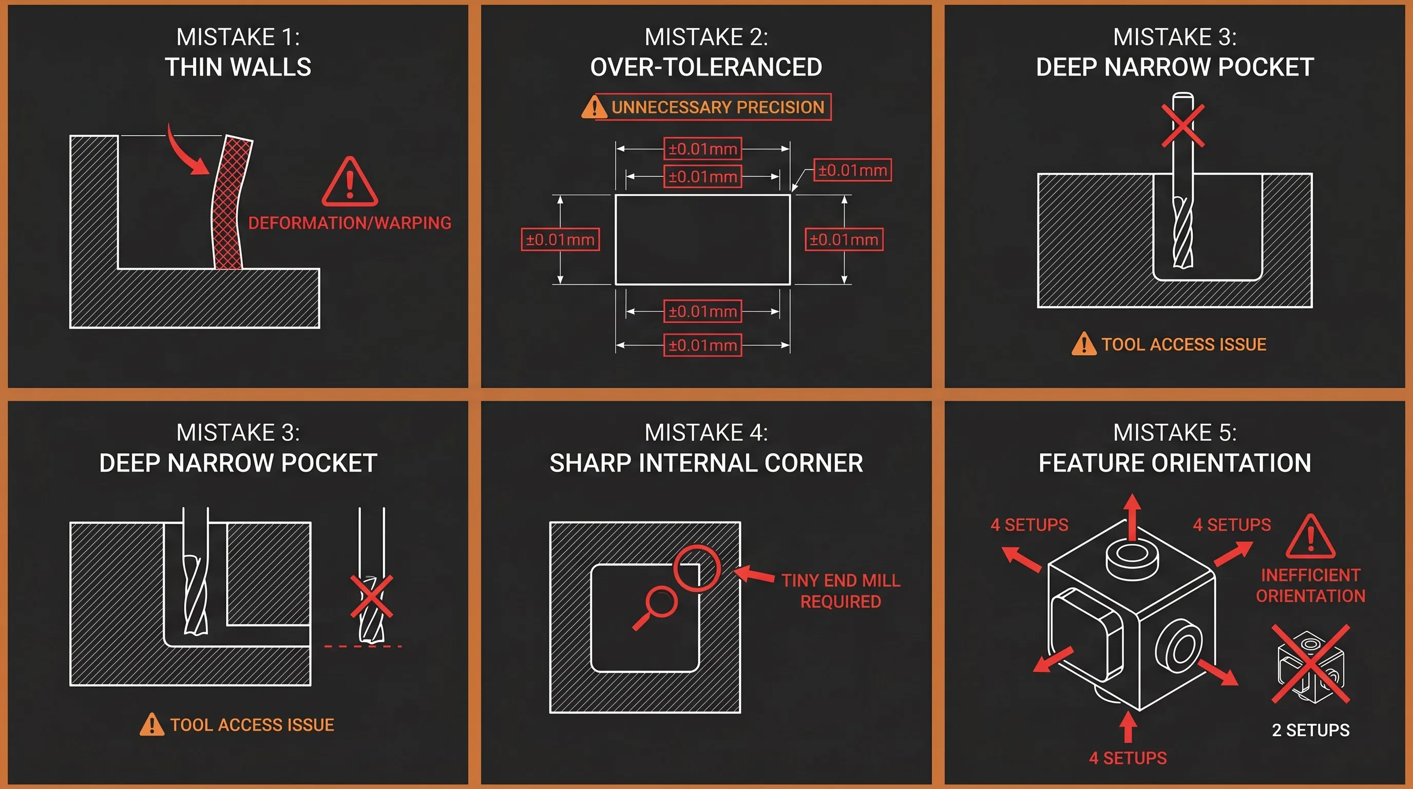
Mistake #1
Walls Too Thin
Walls under 0.8 mm cause chatter, deflection, and dimensional drift. Cost impact: 2–3× baseline.
Mistake #2
Over-Tolerancing
±0.01 mm on all 30+ dimensions forces slow feeds and extra inspection. Cost impact: 3× baseline.
Mistake #3
Deep Narrow Pockets
Depth >3× width requires step-down tools, chatter risk, extended cycle time. Cost impact: 2×+ per feature.
Mistake #4
Sharp Internal Corners
R0 corners need micro-tools, multiple passes, and tool breakage risk. Cost impact: 5–10× per corner.
Mistake #5
Ignoring Tool Access
Features requiring 4+ setups instead of 2 add machine changeover time and positional error. Cost impact: 1.5× per extra setup.
DFM Case Studies — Real Cost Impact
The following two case studies document actual DFM corrections and their measurable impact on unit cost, scrap rate, and lead time. Both projects were manufactured at Goldcattle’s facility, with before-and-after data verified through CMM inspection reports and production tracking.
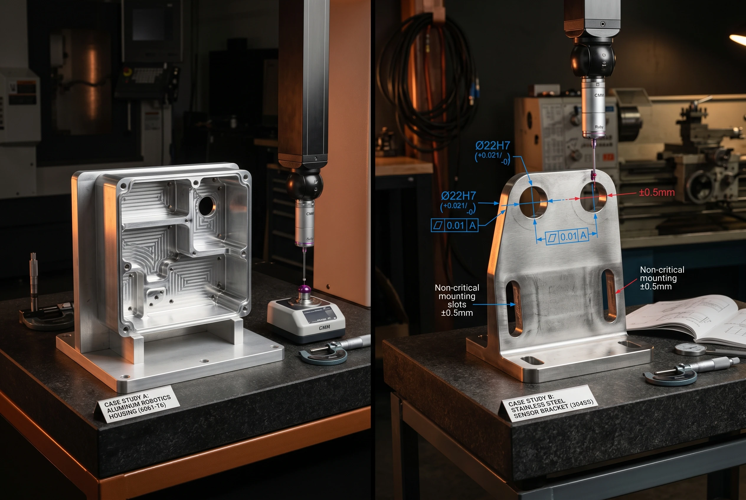
Case Study 1: Aluminum Robotics Housing
| Parameter | Detail |
|---|---|
| Material | 6061-T6 Aluminum |
| Original Design | Wall thickness 0.6 mm on four structural ribs |
| DFM Issue | Part deformation during finishing; 40% scrap rate on first batch |
| DFM Correction | Increase wall thickness to 1.2 mm; add R1.0 mm internal corners |
| Volume | 500 pcs production batch |
Result
| Metric | Before DFM | After DFM |
|---|---|---|
| Unit Cost | \$24.50 | \$16.00 |
| Scrap Rate | 40% | 16% |
| Lead Time | 18 days | 12 days |
35% cost reduction + 60% scrap rate reduction by applying two DFM corrections: wall thickness increase and corner radius addition.
Case Study 2: Stainless Steel Sensor Bracket
| Parameter | Detail |
|---|---|
| Material | Stainless Steel 304 |
| Original Design | ±0.01 mm tolerance on all 32 dimensions |
| DFM Issue | Excessive machining time; slow feeds; extended CMM inspection |
| DFM Correction | Apply ±0.01 mm only to 4 bearing surfaces; ±0.1 mm on 28 non-critical dimensions |
| Volume | 200 pcs production batch |
Result
| Metric | Before DFM | After DFM |
|---|---|---|
| Unit Cost | \$42.00 | \$30.00 |
| Machining Time | 45 min/pc | 28 min/pc |
| Inspection Time | 20 min/pc | 8 min/pc |
28% cost reduction by selectively applying critical tolerances — machining time reduced 38%, inspection time reduced 60%.
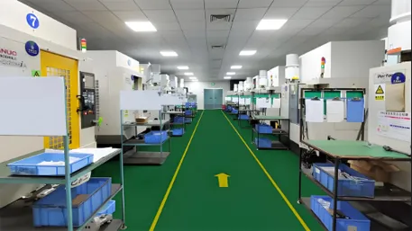
Goldcattle CNC Manufacturing Service
Xiamen Goldcattle Processing Co., Ltd. operates a CNC manufacturing facility with 100+ machining devices — including 5-axis simultaneous machining centers, precision CNC lathes, and Swiss-type turning centers. Every production order receives a free DFM review before quoting, so your drawing is optimized for manufacturability before it enters the production pipeline, not after.
| Capability | Specification |
|---|---|
| CNC Milling | 3-axis, 4-axis, 5-axis simultaneous |
| CNC Turning | Standard + Swiss-type precision lathes |
| Dimensional Tolerance | ±0.01 mm standard, ±0.005 mm geometric |
| Surface Treatments | 20+ processes: anodizing, plating, polishing, passivation, powder coating |
| MOQ | 1 piece (prototype); 100+ pcs (production) |
| Lead Time | 3–7 days (sample); 7–20 days (batch) |
| Quality System | ISO 9001:2015, SGS certified |
| Inspection | CMM verification, runout & concentricity report, surface roughness measurement |
| DFM Service | Free DFM review on every order — cost reduction and manufacturability suggestions included |
6-Step OEM Manufacturing Process
Step 1
DFM Review
Analyze drawing, suggest corrections, optimize for cost
Step 2
CAM Programming
Generate optimized tool paths and cutting parameters
Step 3
CNC Production
Machine parts on 5-axis / lathe / mill equipment
Step 4
Quality Inspection
CMM verification, surface finish, dimensional report
Step 5
Surface Treatment
Anodize, plating, polishing, passivation as specified
Step 6
Shipment
Pack, document, ship with full QC paperwork
Need a DFM Review? Upload Your Drawing
Every drawing submitted to Goldcattle receives a free DFM analysis before quoting — identifying wall thickness issues, over-toleranced dimensions, inaccessible features, and cost reduction opportunities. You receive actionable suggestions, not just a price quote.
Accepted File Formats
- STEP / STP — 3D solid model (preferred)
- IGES / IGS — Surface model
- DWG / DXF — 2D drawing with dimensions and tolerances
What You Receive
- Free DFM Analysis — manufacturability feedback
- Material Recommendation — best material for your application
- Cost Analysis + CNC Machining Quote — pricing based on optimized geometry
Contact: charlie@plasticmetalparts.com — Send your STEP/STP/DWG file for free DFM review and cost analysis
CNC DFM Frequently Asked Questions
What wall thickness should I specify for aluminum CNC parts?
Minimum 1.0 mm for non-load-bearing features, 1.2–1.5 mm preferred for structural walls. Walls under 0.8 mm cause machining chatter and dimensional instability — expect 2–3× cost increase on thin-wall parts.
Why can’t CNC machines cut sharp internal corners?
CNC end mills are cylindrical tools — the minimum internal radius equals half the tool diameter. A sharp 90-degree corner requires a micro-diameter tool (0.1–0.2 mm), which breaks easily and adds 5–10× machining time per corner. Specify R0.5 mm minimum on all internal corners.
How much does tolerance affect CNC machining cost?
±0.1 mm is baseline cost (1× multiplier). ±0.05 mm adds 20%. ±0.02 mm adds 2×. ±0.01 mm adds 3× or more. Apply tight tolerances only to functional mating surfaces — bearing bores, shaft seats, alignment holes — and use ±0.1 mm for all other dimensions.
How deep can a CNC-machined hole be?
Standard twist drills reliably produce holes up to 3× their diameter (L/D ≤3). Extended-length drills handle 3–5× diameter. Beyond 5× diameter requires gun drilling, which is a specialized process with higher cost and limited supplier availability. Design blind holes with L/D ≤3 whenever possible.
What is the maximum pocket depth for CNC machining?
Design pocket depth ≤2.5–3× the pocket width. A 10 mm wide pocket should not exceed 25–30 mm depth. Beyond this ratio, machining requires progressively smaller tools for corner cleanup, introduces chatter risk from long tool overhang, and increases cycle cost by 2× or more per feature.
Which material is cheapest to CNC machine?
Brass C360 (100% machinability rating) and Aluminum 6061-T6 (very high machinability) are the lowest-cost CNC materials. Both cut at high spindle speeds with minimal tool wear. Stainless steel adds 40–60% cost over aluminum. Copper and titanium add 80–120% cost due to gummy cutting behavior and extreme tool wear.
Should I use threaded inserts or tapped threads in aluminum?
For any thread that will be assembled/disassembled more than 5 times, or that carries load in a soft material (aluminum, plastic), specify helical brass inserts (Helicoil style). Direct tapped threads in aluminum strip under repeated use and vibration. Inserts cost more per hole but eliminate thread failure risk.
What does a DFM review include?
Goldcattle’s free DFM review examines your drawing for: wall thickness below recommended minimums, sharp internal corners that require micro-tools, over-toleranced non-functional dimensions, pocket depth-to-width ratios exceeding 3:1, hole depth ratios exceeding 5× diameter, and setup complexity that could be reduced through feature reorientation. You receive written suggestions with cost impact estimates before the production quote.
Can I get a prototype before committing to batch production?
Yes — Goldcattle accepts MOQ 1 piece for prototype orders with 3–7 day lead time. Prototype production includes full CMM dimensional verification, so you can validate geometry and tolerances before scaling to batch volume. This two-stage approach (prototype → DFM feedback → batch) eliminates the risk of producing 200+ parts from an unvalidated drawing.
Related CNC Manufacturing Pages
This DFM design guide belongs to Goldcattle’s CNC machining topic cluster. Each linked page addresses a specific procurement or technical question that complements the DFM rules covered here.
Full-service manufacturing overview — capabilities, materials, surface treatments, MOQ, lead time
Complex geometry capability — simultaneous 5-axis for aerospace, medical, precision components
Multi-metal manufacturing — aluminum, brass, stainless, copper, bronze from prototype to volume
When CNC cost exceeds volume threshold — stamping for 500+ pcs high-volume flat parts
Structured Data Summary
| Property | Value |
|---|---|
| Page Topic | CNC Part Design Guide: DFM Rules to Reduce Cost and Improve Manufacturability |
| Target Keywords | how to design parts for cnc machining, cnc design guidelines, cnc machining dfm guide, design for manufacturability cnc, cnc machining cost reduction |
| Content Type | DFM Procurement Guide + Engineering Reference |
| DFM Rules Covered | 5 rules: Wall Thickness, Internal Corners, Tolerances, Hole Design, Pocket Geometry |
| Materials | 7 materials: 6061-T6, 7075-T6, 304 SS, 316 SS, Brass C360, Copper C110, POM |
| Cost Impact Data | Tolerance multiplier table, wall thickness cost impact, pocket depth ratio cost |
| Case Studies | 2 documented: Aluminum Robotics Housing (35% cost reduction), SS Sensor Bracket (28% cost reduction) |
| Manufacturer | Xiamen Goldcattle Processing Co., Ltd. — ISO 9001:2015, SGS certified |
| Service Offer | Free DFM review on every drawing submission |
| EEAT Author | Chen — 18 Years CNC Manufacturing Engineering, Goldcattle Technical Director |
| Internal Links | 4 related pages in CNC machining topic cluster |
| Last Updated | June 2026 |