Custom Metal Stamping Services
High-Precision Stamped Components — From Prototype Tooling to Mass Production
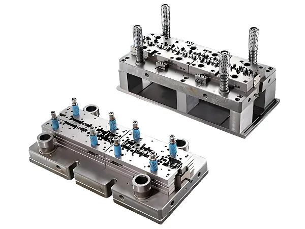
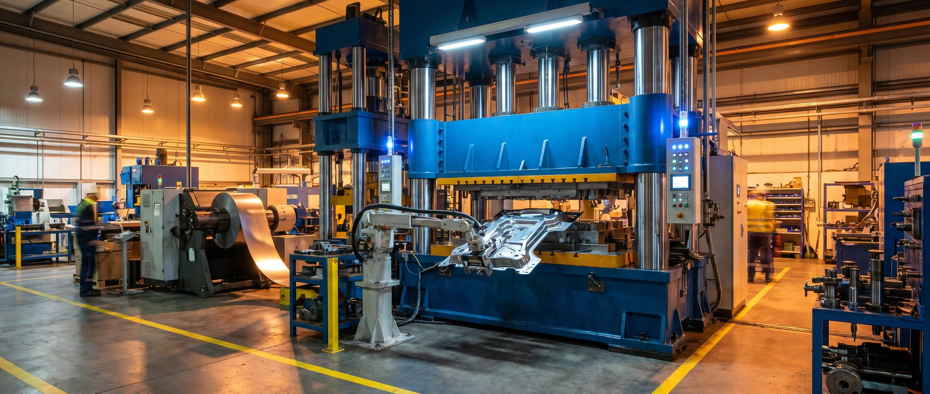
Xiamen Goldcattle delivers precision-stamped metal components for automotive, electrical, appliance and industrial applications. Our facility houses progressive die presses up to 400 tons, deep-draw equipment, and dedicated QC stations — supporting volumes from 100-piece pilot runs to 500,000+ annual production.
- Automotive brackets, clips and structural mounts
- Electrical terminals, busbars and connector contacts
- Appliance housings, structural supports and panels
- Industrial mounting hardware, covers and enclosures
What Can We Stamp?
Four stamping methods cover virtually any thin-metal component requirement. Each technique targets a distinct geometry and production volume profile — choosing the right one directly affects unit cost and lead time.
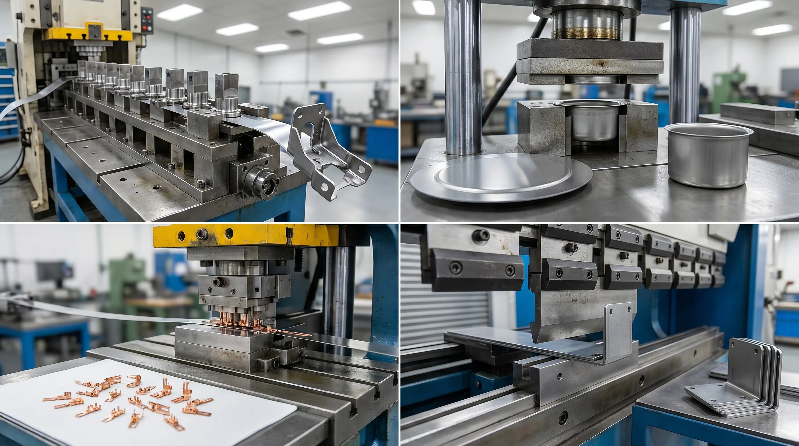
Progressive Die Stamping
Deep Draw Stamping
Precision Stamping
Bending & Forming
Stamping Process Selection Guide
| Process | Volume Range | Material Thickness | Geometry Type | Tooling Cost | Unit Cost |
|---|---|---|---|---|---|
| Progressive Die | 10,000+ | 0.2–3 mm | Flat / shallow bends | Higher ($2,000–$8,000) | Very Low |
| Deep Draw | 5,000+ | 0.5–3 mm | Cylindrical / box | Moderate ($1,500–$5,000) | Low |
| Precision Stamp | 3,000+ | 0.1–1 mm | Flat / fine features | Moderate ($1,200–$4,000) | Low |
| Bend & Form | 100+ | 0.5–6 mm | Angled / multi-bend | Low ($300–$1,500) | Moderate |
Metal Materials Available for Stamping
Material choice determines corrosion resistance, conductivity, formability and unit cost. Below are the six alloys most frequently specified by our OEM buyers, with typical application segments and forming considerations.
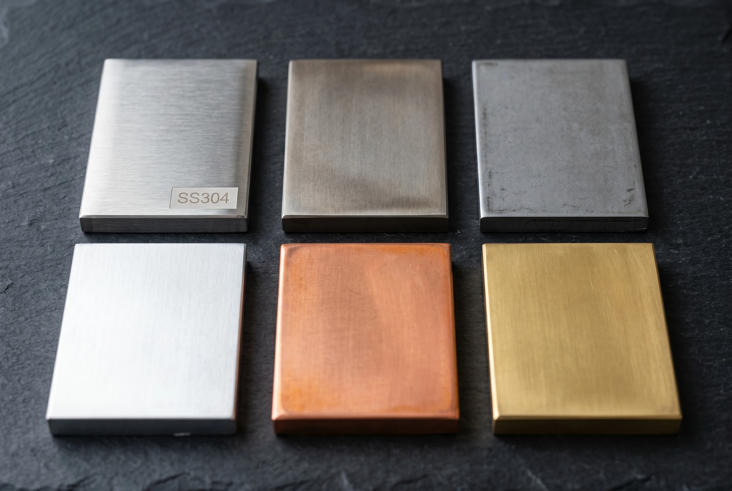
| Material | Thickness Range | Formability | Typical Application | Key Property |
|---|---|---|---|---|
| Stainless Steel 304 | 0.3–3 mm | Good | Industrial equipment brackets | Corrosion resistance, weldability |
| Stainless Steel 316 | 0.3–2 mm | Moderate | Medical & marine hardware | Pitting resistance, chloride tolerance |
| SPCC Cold-Rolled Steel | 0.5–4 mm | Excellent | General hardware & enclosures | Low cost, easy forming |
| Aluminum 5052 | 0.3–3 mm | Excellent | Lightweight structural parts | Weight reduction, anodizable |
| Copper C110 | 0.1–2 mm | Very Good | Electrical contacts & busbars | Electrical conductivity |
| Brass C360 | 0.2–2 mm | Excellent | Connectors & terminals | Machinability + conductivity |
Material Selection Decision Guide
Choose Stainless Steel If You Need
Corrosion resistance for outdoor or wash-down environments, food-grade compliance, long service life without plating, high-temperature stability.
Choose Aluminum If You Need
Weight reduction in moving assemblies, anodized color finishes, heat dissipation in electronic enclosures, easy forming for complex bend geometries.
Choose Copper / Brass If You Need
High electrical conductivity for contacts and busbars, spring-back tolerance in terminals, low friction in sliding contacts, decorative gold finish on brass.
Industries We Serve
Stamped metal components appear in nearly every manufactured product category. Four sectors generate the highest volume of stamping orders at Goldcattle — each with distinct geometry, material and tolerance requirements.
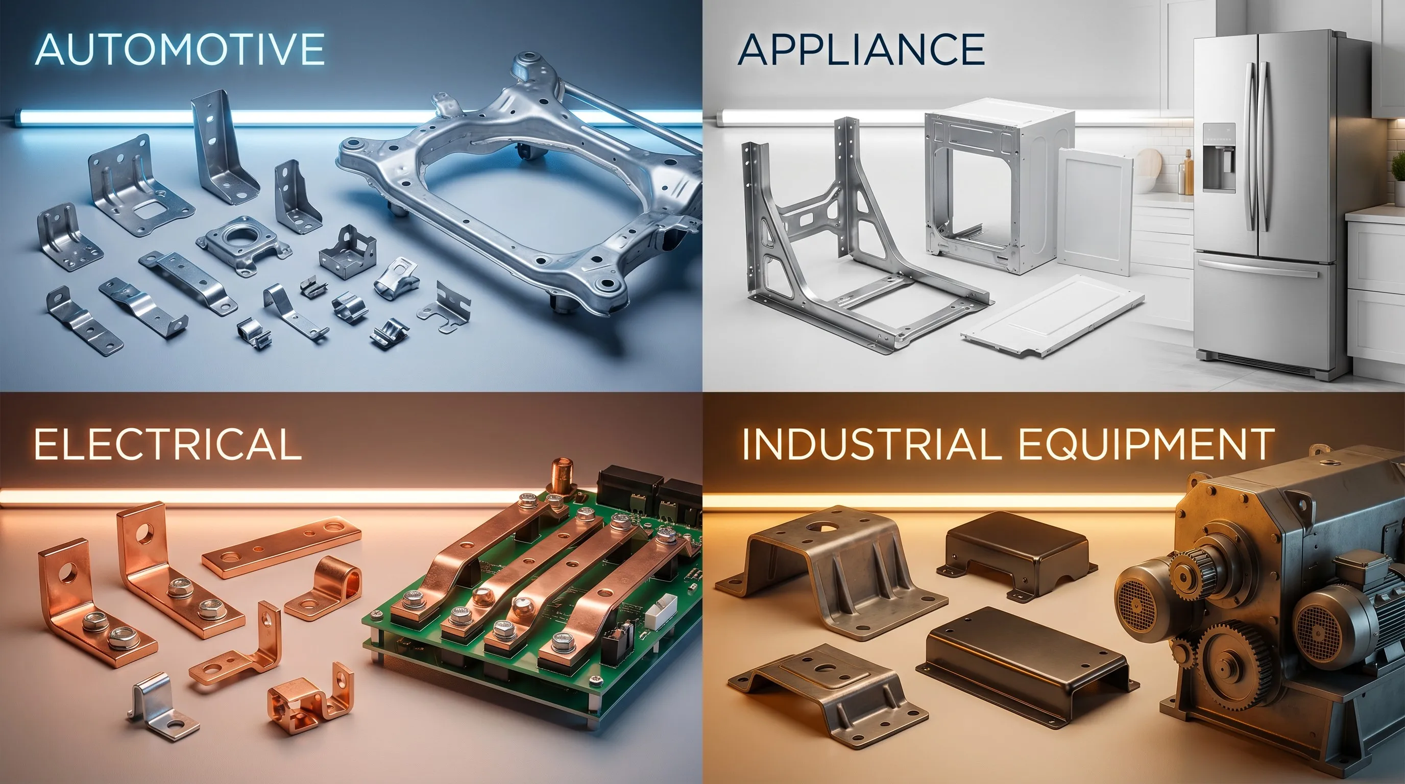
Automotive
Typical spec: SS304/SPCC, 0.5–2.5mm, ±0.05mm tolerance, 50K–500K/year volume
Electrical & Electronics
Typical spec: Copper/Brass, 0.1–1mm, ±0.02mm precision, plating required (tin/gold)
Appliances & HVAC
Typical spec: SPCC/Galvanized, 0.5–3mm, ±0.1mm tolerance, surface treatment required
Industrial Equipment
Typical spec: SS304/Al5052, 1–4mm, ±0.08mm tolerance, prototype to 100K/year
When Should You Choose Stamping Over CNC?
Both stamping and CNC machining produce precision metal components — but they serve fundamentally different production profiles. Stamping excels at high-volume, thin-sheet parts; CNC excels at complex 3D geometries and low-volume prototypes. Understanding this trade-off is essential for procurement decisions.
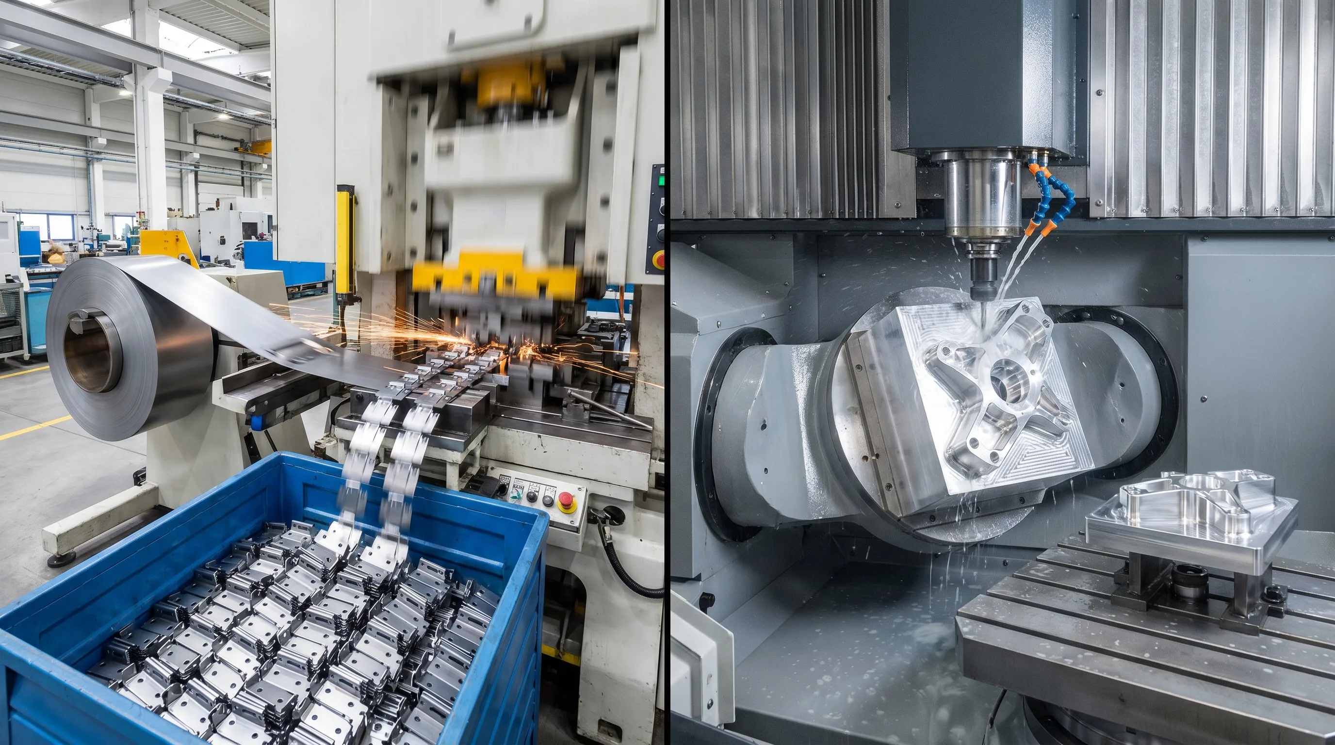
| Factor | Stamping | CNC Machining |
|---|---|---|
| High Volume | Excellent — cycle time <1 sec | Moderate — 5–45 min per part |
| Tooling Cost | Higher ($2K–$8K die set) | Lower (no dedicated tooling) |
| Unit Cost at Scale | Very low ($0.05–$2 per part) | Higher ($5–$50 per part) |
| Complex 3D Features | Limited — flat + bends only | Excellent — full 3D freedom |
| Production Speed | Excellent — hundreds per hour | Moderate — hours per batch |
| Material Thickness | 0.2–6 mm sheet only | Any thickness / solid block |
| Dimensional Repeatability | Excellent — die-controlled | Good — program-controlled |
| Prototype Phase | Slow — die must be built first | Fast — program in hours |
Decision Rule: Choose Stamping When
Volume > 5,000 pcs
Stamping unit cost drops dramatically above 5,000 units because the die investment amortizes across the production run. Below this threshold, CNC or laser cutting is usually more economical.
Thin Metal Sheet Parts
Components under 6mm thickness with flat or bent profiles are stamping’s natural domain. CNC wastes material and time milling thin sheets that a press forms in a single stroke.
Consistent Dimensions Required
Once a die is set, every part is identical — dimensional variation comes from die wear, not operator skill. For tight batch-to-batch repeatability, stamping is superior to manual CNC setup changes.
5 Common Stamping Design Mistakes (and How to Fix Them)
These five errors account for 80% of DFM failures in stamped component orders. Avoiding them reduces tooling cost, shortens lead time and eliminates batch-to-batch variation.
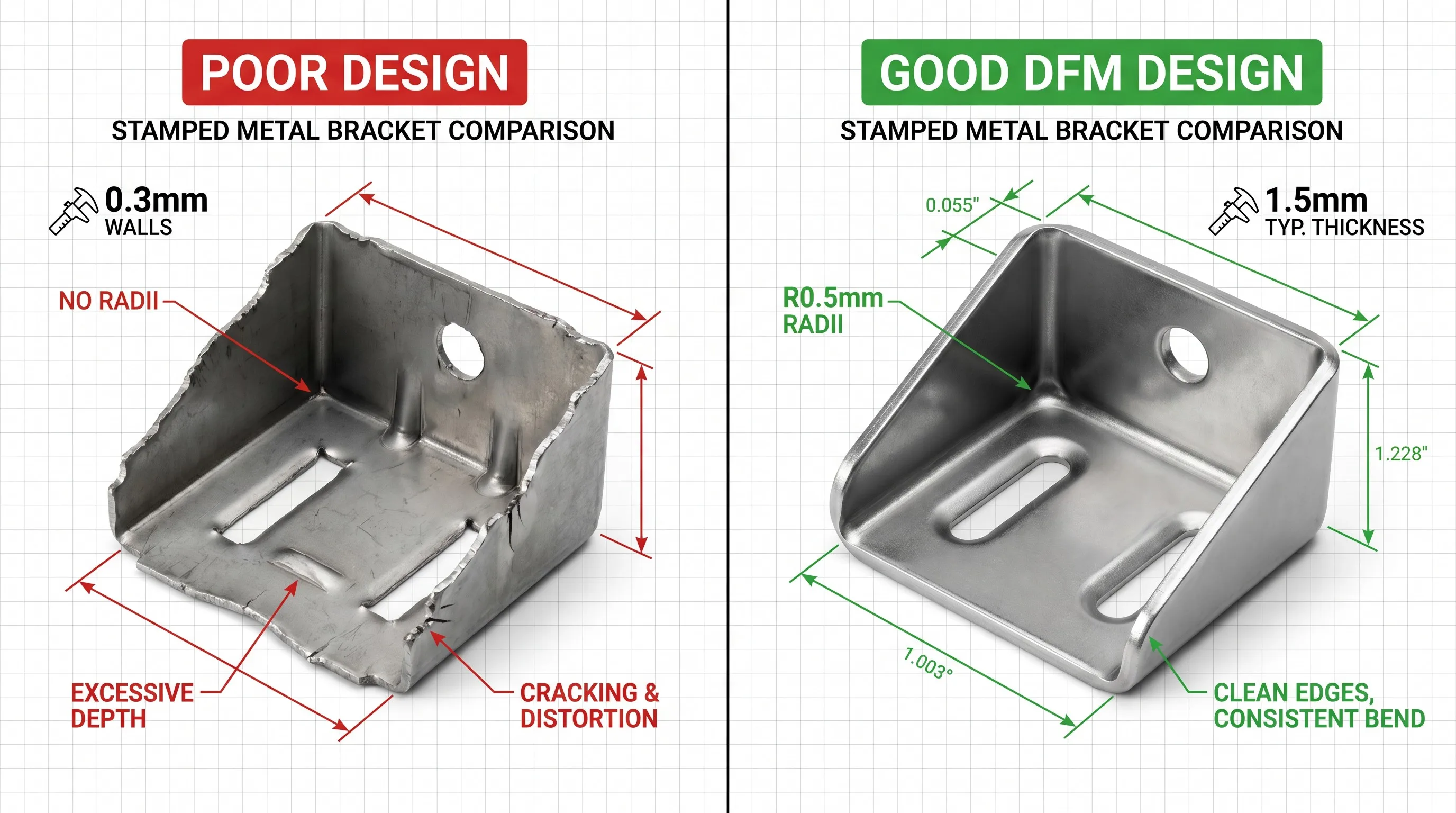
1. Walls Below Minimum Thickness
2. Sharp Internal Corners Without Radii
3. Over-Specified Tolerances on Non-Critical Features
4. Excessive Bend Relief Notches Missing
5. Ignoring Grain Direction on Deep Draws
DFM Review Recommendation
Quality Assurance Protocol
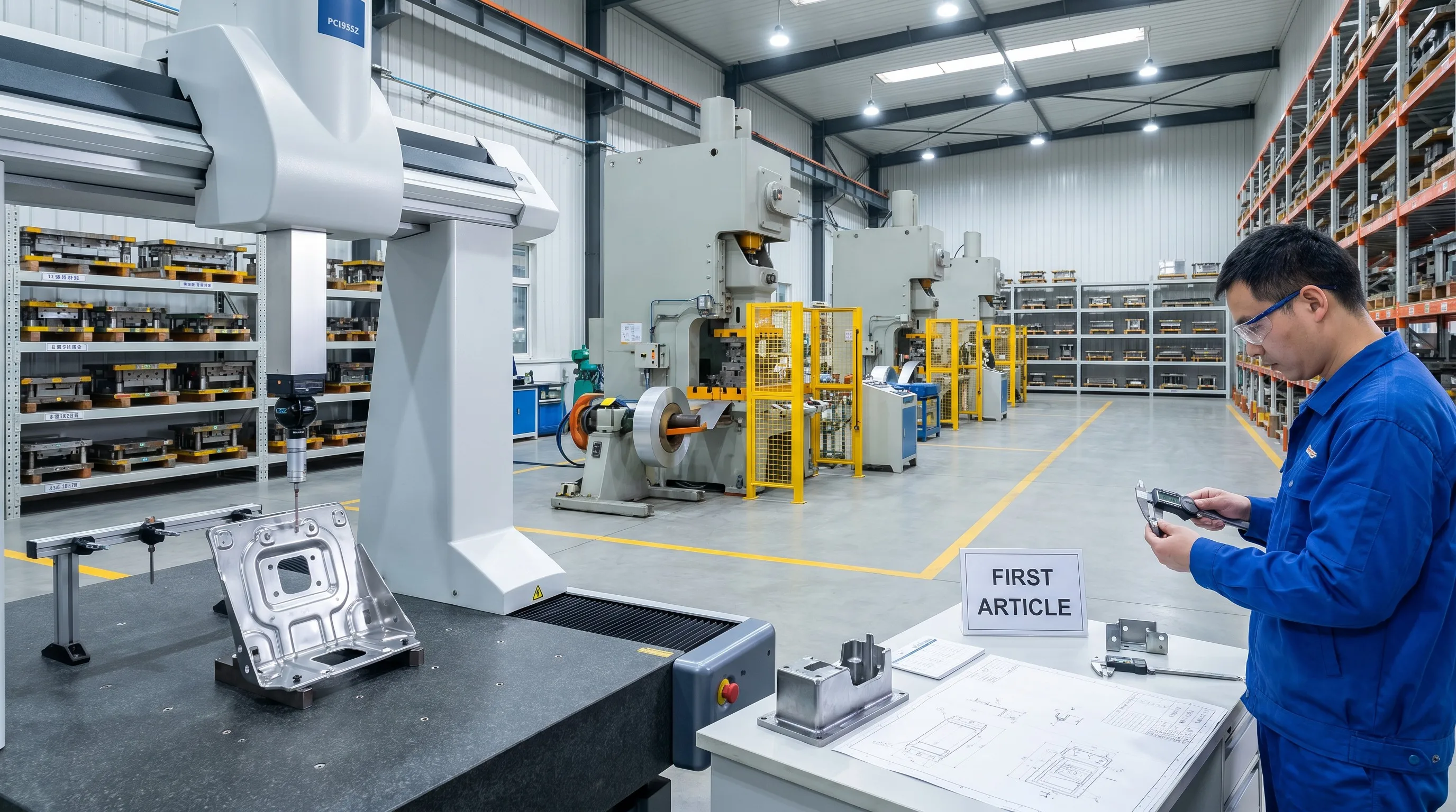
Every stamped order passes through a three-stage inspection protocol aligned with ISO 9001:2015. First Article Inspection validates the die setup; in-process checks catch drift during production; final inspection confirms dimensional compliance before shipment.
| Inspection Stage | Method | Scope | When | Output |
|---|---|---|---|---|
| First Article Inspection | CMM + visual | All critical dimensions per drawing | First 3–5 pcs after die setup | FAI report with measured values vs spec |
| In-Process Inspection | Digital caliper + go/no-go gauge | Key dims every 500 pcs | During production run | SPC chart, deviation log |
| Final Inspection | CMM + surface visual | Full dimension set + surface quality | Before packaging | COC report, dimensional summary |
| Material Certification | Mill certificate review | Alloy composition, mechanical properties | Incoming material stage | Material COC per ASTM/EN standard |
Tolerance Standards by Feature Type
| Feature | Standard Tolerance | Precision Tolerance | Cost Impact |
|---|---|---|---|
| Hole position | ±0.1 mm | ±0.05 mm | Standard: baseline — Precision: +20% die cost |
| Bend angle | ±1° | ±0.5° | Standard: baseline — Precision: +15% die cost |
| Blank outline | ±0.15 mm | ±0.05 mm | Standard: baseline — Precision: +25% die cost |
| Surface flatness | 0.2 mm / 100mm | 0.1 mm / 100mm | Standard: baseline — Precision: +10% tooling cost |
| Bend radius | R ≥ 1× thickness | R ≥ 0.5× thickness | Standard: baseline — Precision: +30% die cost |
Case Studies: Stamped Component Projects
Three recent projects illustrate how stamping method, material choice and DFM review directly impact production outcomes — from tooling cost to dimensional pass rate.
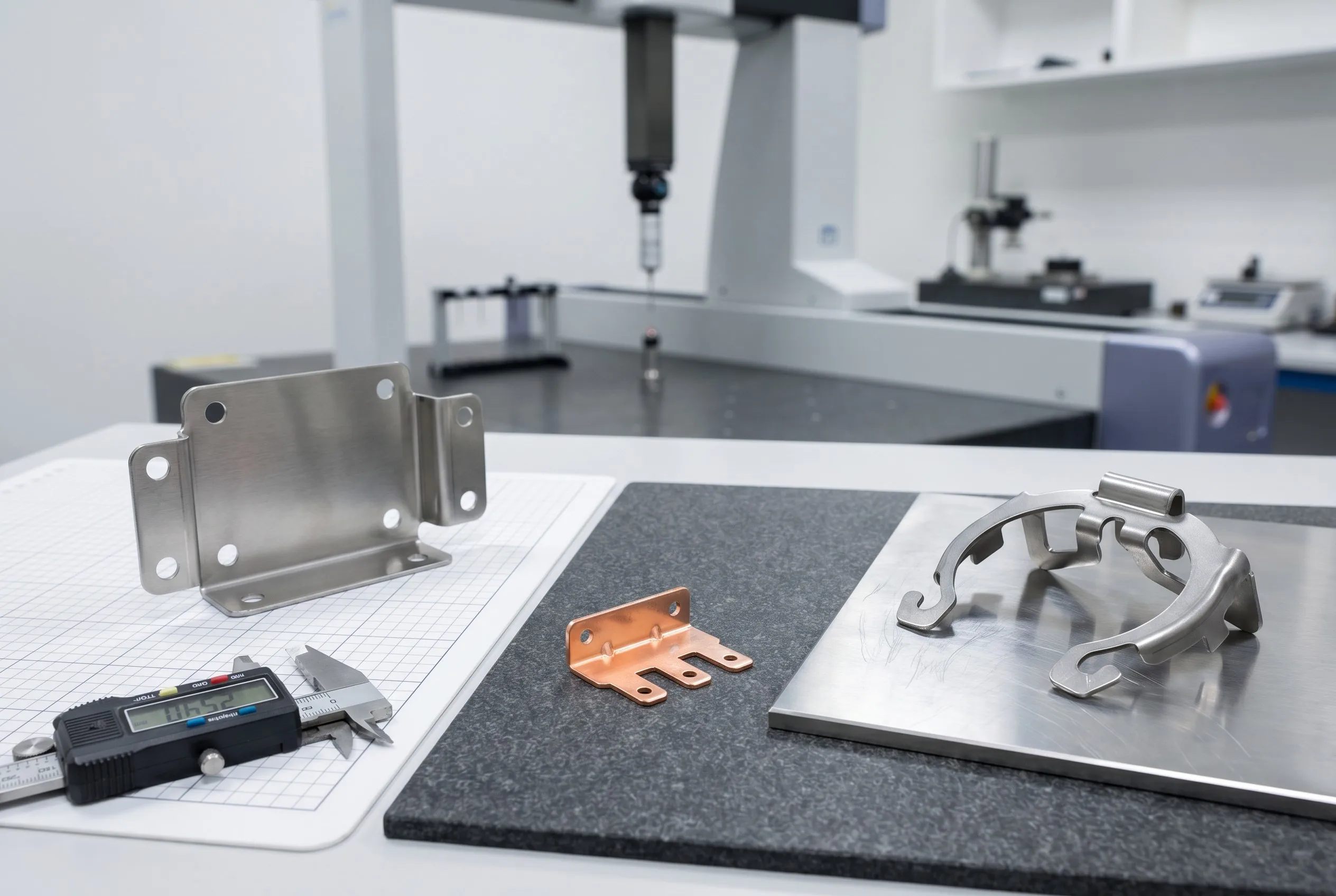
Stainless Steel Mounting Bracket
Copper Electrical Contact
Automotive Retaining Clip
Xiamen Goldcattle — Custom Stamping OEM Partner
Goldcattle operates a dedicated stamping division alongside CNC machining, injection molding and sheet metal fabrication lines. This integration means your stamped components can move directly into secondary operations — tapping, welding, surface treatment — without changing suppliers.
| Capability | Specification |
|---|---|
| Press Capacity | 25T – 400T (6 presses) |
| Material Thickness Range | 0.2 – 6 mm |
| Max Blank Size | 600 × 400 mm |
| Tolerance (Standard) | ±0.05 mm |
| Tolerance (Precision) | ±0.02 mm |
| Surface Treatment | Passivation, zinc plating, nickel plating, anodizing, powder coating, painting |
| Secondary Operations | Tapping, welding (spot/TIG/MIG), riveting, assembly |
| QC Standard | ISO 9001:2015, CMM inspection, SPC monitoring |
| Certifications | ISO 9001, RoHS compliant materials available |
6-Step OEM Process
Request a Stamping Quote
Upload your drawing files and receive a comprehensive quotation covering tooling, production and delivery — within 24 hours for standard requests.
Upload Your Files
What You Receive
Frequently Asked Questions
| Property | Value |
|---|---|
| Service Type | Custom Metal Stamping |
| Processes Available | Progressive Die, Deep Draw, Precision, Bend & Form |
| Material Range | SS304/316, SPCC, Al5052, Copper C110, Brass C360 |
| Thickness Range | 0.2 – 6 mm |
| Standard Tolerance | ±0.05 mm |
| Precision Tolerance | ±0.02 mm |
| MOQ | 100 pcs (bending) / 3,000 pcs (progressive die) |
| Lead Time | 7–25 days (tooling + production) |
| Surface Treatment | Passivation, zinc/nickel/tin plating, anodizing, powder coating |
| QC Standard | ISO 9001:2015, FAI + SPC + Final Inspection |
| Industries | Automotive, Electrical, Appliance, Industrial Equipment |
| Manufacturer | Xiamen Goldcattle Precision Industry Co., Ltd. |