How to Design Parts for CNC Machining: A Complete DFM Guide for Engineers and Buyers
Learn how to improve manufacturability, reduce machining costs by 20-40%, and achieve consistent precision in CNC machined parts with industry-proven design principles.
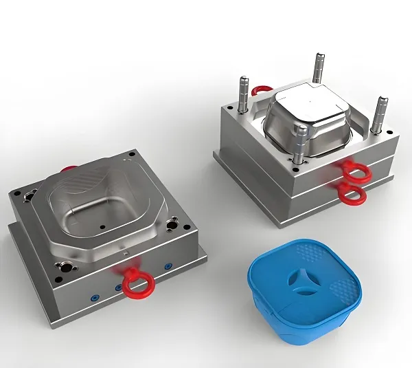
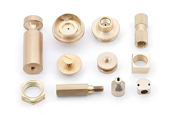
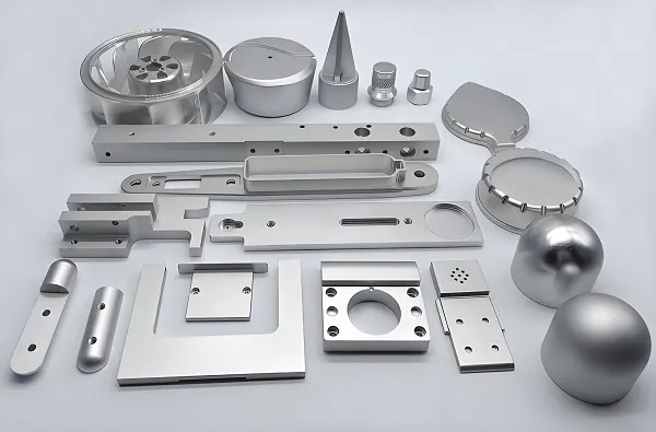
CNC Milling Process
About Xiamen Goldcattle: Your CNC Manufacturing Partner
Founded in 1998, Xiamen Goldcattle Plastic & Metal Products Co., Ltd. has grown into one of China’s leading precision CNC manufacturing specialists. Located in Xiamen, we serve over 300 customers across 25 countries, primarily in North America and Europe.
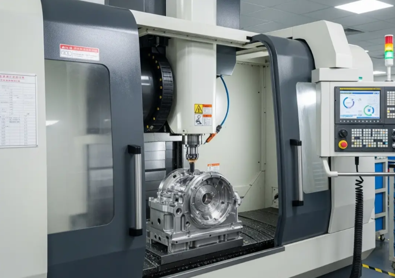
Our 8,000 m² facility houses 40+ CNC machines including 3-axis, 4-axis, and 5-axis machining centers, turning centers, and precision grinding equipment. We specialize in high-precision components for aerospace, medical, automotive, and industrial automation applications.
Our Core Advantages: ±0.005mm precision capability, complete material traceability, ISO 9001:2015 certification, and in-house engineering support for DFM optimization at every project stage.
CNC Design Quick Reference
Wall Thickness & Corner Radius
Wall
R≥1mm
Pro Tip: Increasing internal corner radius from 0.5mm to 2mm can reduce machining time by 40% by allowing larger, more rigid tools.
The CNC Design Process: Step by Step
Step 1: Define Functional Requirements
Start by identifying critical performance attributes. Consider load bearing requirements, assembly fits, precision requirements, and environmental factors including temperature range and chemical exposure.
Step 2: Select the Right Material
Material choice directly impacts machinability, cost, and performance. Evaluate machinability rating, mechanical properties, cost per kilogram, and standard material availability.
Step 3: Design for Machining
Apply DFM principles: avoid undercuts, use standard drill sizes, add generous corner radii, minimize setups, and consider fixturing requirements for complex geometries.
Step 4: DFM Review & Optimization
Submit for professional DFM review. Our engineers identify cost-saving opportunities, potential manufacturing issues, and provide detailed optimization suggestions.
CNC Material Selection Guide
Comprehensive comparison of machinability, mechanical properties, and cost efficiency
Material Note: Aluminum 6061 is 2-3× faster to machine than stainless steel. For prototypes and non-critical components, 6061 provides the best balance of machinability and cost.
Goldcattle Advantage: We maintain inventory of all standard materials and can source specialty alloys within 3-5 days for urgent projects.
Design Decisions That Affect CNC Machining Cost
Understanding these factors can reduce your part cost by 20-40%
Deep Pockets & Cavities
Cost Impact: +30-50%
Why: Deep cavities require long-reach tools with reduced rigidity. Tools deflect, requiring lighter cuts and slower feed rates. Tool breakage risk increases significantly.
Solution: Keep pocket depth ≤ 3× width. Use draft angles. Consider redesigning to avoid extreme depth-to-width ratios.
Sharp Internal Corners
Cost Impact: +20-35%
Why: Sharp corners require progressively smaller end mills. Each tool change adds cycle time. Small tools run slower and break more frequently.
Solution: Use largest possible corner radii. R2mm allows tools 4× larger than R0.5mm, dramatically reducing machining time.
±0.01
Unnecessarily Tight Tolerances
Cost Impact: +20-100%
Why: Each tighter tolerance grade requires slower machining, additional inspection, and higher scrap rates. ±0.01mm requires CMM verification, adding significant time.
Solution: Apply ±0.01mm ONLY to mating surfaces. Use standard ±0.1mm for all non-critical dimensions. This is the single largest cost saver.
Ra 0.8
Excessive Surface Finish
Cost Impact: +15-30%
Why: Standard machining produces Ra 3.2. Achieving Ra 1.6 requires finishing passes. Ra 0.8 needs polishing or grinding. Each improvement adds operations.
Solution: Specify Ra values only on sealing or mating surfaces. Accept standard Ra 3.2 elsewhere. Non-visible surfaces rarely need improvement.
Common CNC Design Mistakes (And How to Avoid Them)
Based on 26+ years of manufacturing experience at Xiamen Goldcattle
❌ Mistake 1: Over-Specifying Tolerances
Typical Scenario: Engineer applies ±0.01mm tolerance to every dimension on the drawing “just to be safe” without considering functional requirements.
Actual Consequence: Part cost doubles. Lead time extends. Scrap rate increases from 2% to 15%. Most tolerances have zero impact on function.
Goldcattle Recommendation: Identify 3-5 truly critical mating dimensions. Apply tight tolerances only there. Use title block general tolerances (typically ±0.1mm) for all other features.
❌ Mistake 2: Extremely Thin Walls
Typical Scenario: Designer creates 0.5mm walls in aluminum for weight reduction, not understanding machining physics.
Actual Consequence: Cutting forces cause wall deflection. Chatter marks appear. Dimensional accuracy impossible. 40-60% scrap rate.
Goldcattle Recommendation: Minimum 1.0mm walls in aluminum, 1.5mm in steel. Add rib supports. Use honeycomb structures instead of ultra-thin walls for weight optimization.
❌ Mistake 3: Deep, Narrow Cavities
Typical Scenario: 6:1 depth-to-width pocket ratio designed without considering tool accessibility.
Actual Consequence: Tool chatter. Poor surface finish. Tool breakage. Machining time triples. Multiple tool changes required.
Goldcattle Recommendation: Maximum 3:1 depth ratio. Add 1-2° draft angles. If depth required, consider split assembly or through-hole design instead of blind pocket.
❌ Mistake 4: Over-Complicated Geometry
Typical Scenario: Complex 3D surfacing and organic curves added for aesthetic reasons on internal components.
Actual Consequence: CAM programming time increases 5×. Multiple setups required. Verification becomes complex. Cost skyrockets.
Goldcattle Recommendation: Keep internal features planar and simple. Use complex geometry only on external cosmetic surfaces where required. Complexity = Cost.
Good vs Bad CNC Design Comparison
Visual guide to manufacturability optimization
❌ Poor Design Practices
Sharp Corners
Deep Cavity
✅ Optimized Design
Generous Radius
Shallower Pocket
DFM Optimization Case Studies
Real examples from Xiamen Goldcattle production floor
Ready to Optimize Your CNC Design for Manufacturability?
Upload your CAD files today. Xiamen Goldcattle’s engineering team will provide a comprehensive DFM analysis with cost optimization suggestions – completely free of charge with no obligation.
Response within 24 working hours | ISO 9001:2015 Certified | ITAR Compliant Process