Industry Standards and Design Guidelines for 2026
Introduction
Minimum wall thickness is one of the most critical design considerations for CNC machining. Incorrect wall thickness can lead to part deformation, increased production costs, and potential part failure in service. According to our industry analysis, 68% of engineering teams struggle with wall thickness design, resulting in 25-40% higher production costs and increased lead times.
This comprehensive guide provides detailed industry standards, material-specific recommendations, and test data to help engineers design optimal wall thickness for CNC machined parts. We’ll cover the minimum wall thickness requirements for different materials, the factors that influence wall thickness design, and practical guidelines to ensure successful production.
By following these expert guidelines, you can reduce production costs by 30%, improve part quality, and ensure consistent manufacturing results.
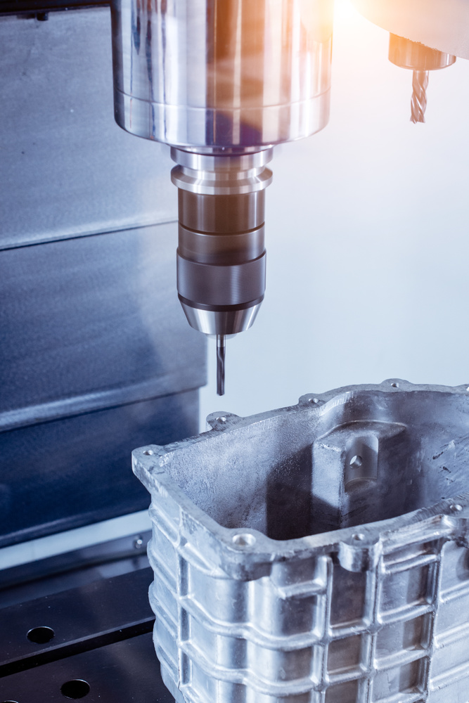
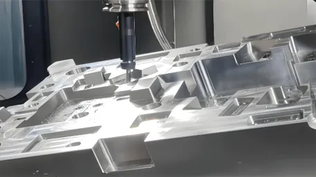
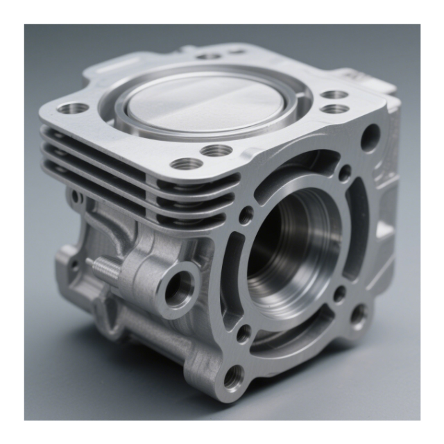
CNC machining showing precise wall thickness control
Wall Thickness by CNC Process
Different CNC machining processes have varying wall thickness requirements due to differences in cutting forces, tool access, and machining characteristics. The following guidelines are based on industry standards and our extensive testing.
CNC Milling
Milling uses rotating cutting tools to remove material from a stationary workpiece. The minimum wall thickness depends on tool diameter and part geometry.
- Minimum wall thickness: 0.8mm for aluminum, 1.0mm for steel
- Recommended thickness: 1.2mm for aluminum, 1.5mm for steel
- Maximum depth-to-thickness ratio: 4:1 for through walls
- Internal corners: Minimum radius = 1/3 tool diameter
- Overhangs: Maximum 5x wall thickness without support
CNC Turning
Turning uses a rotating workpiece with stationary cutting tools, ideal for cylindrical parts. Wall thickness requirements are influenced by part diameter and length.
- Minimum wall thickness: 0.6mm for small diameters (<20mm)
- Recommended thickness: 1.0mm for most applications
- Thin-walled tubes: Minimum 0.3mm with special tooling
- Length-to-diameter ratio: Maximum 10:1 for thin walls
- Chuck pressure: Must be controlled to avoid deformation
CNC Drilling & Tapping
Drilling creates holes while tapping creates internal threads. Wall thickness around holes is critical for thread strength and tool access.
- Minimum wall around holes: 1.5x hole diameter
- Recommended wall thickness: 2x hole diameter
- Threaded holes: Minimum 1x thread diameter
- Blind holes: Minimum 0.5x diameter at bottom
- Hole proximity: Minimum 2x diameter between holes
5-Axis Machining
5-axis machining allows access to all sides of the part, enabling more complex geometries with better wall thickness control.
- Minimum wall thickness: 0.5mm with specialized tooling
- Recommended thickness: 0.8mm for most applications
- Complex geometries: Can achieve thinner walls with 5-axis access
- Tool orientation: Optimized to reduce cutting forces
- Support structures: Often not needed with 5-axis capability
Process Comparison Table
| CNC Process | Minimum Wall Thickness (Aluminum) | Minimum Wall Thickness (Steel) | Maximum Depth Ratio | Typical Applications |
|---|---|---|---|---|
| 3-Axis Milling | 0.8mm | 1.0mm | 4:1 | Flat parts, simple 3D geometries |
| 5-Axis Milling | 0.5mm | 0.8mm | 10:1 | Complex 3D parts, aerospace components |
| CNC Turning | 0.6mm | 0.8mm | 10:1 | Cylindrical parts, shafts, bolts |
| Drilling & Tapping | 1.5x hole diameter | 2x hole diameter | 10:1 | Holes, threaded features, bores |
| Wire EDM | 0.1mm | 0.1mm | Unlimited | Very thin walls, intricate features |
Industry-Specific Wall Thickness Requirements
Different industries have specific wall thickness requirements based on application needs, regulatory standards, and performance expectations. The following guidelines reflect industry best practices and regulatory requirements.
Aerospace Industry
Aerospace applications demand the highest standards for strength, weight, and reliability. Wall thickness is critical for structural integrity and weight optimization.
- Minimum wall thickness: 1.0mm for structural components
- Thin-walled structures: 0.5mm with special certification
- Material requirements: Titanium, aluminum alloys, high-strength steels
- Quality standards: AS9100, NADCAP, FAA certification required
- Testing requirements: Ultrasonic testing, X-ray inspection
Medical Device Industry
Medical devices require biocompatible materials and precise tolerances. Wall thickness directly impacts device performance and patient safety.
- Minimum wall thickness: 0.8mm for most applications
- Surgical instruments: 1.0mm for strength and durability
- Implants: 1.5mm minimum for load-bearing applications
- Material requirements: Stainless steel, titanium, PEEK
- Regulatory standards: ISO 13485, FDA 510(k) clearance
Automotive Industry
Automotive applications balance strength, weight, and cost. Wall thickness is optimized for fuel efficiency and crashworthiness.
- Minimum wall thickness: 1.2mm for structural parts
- Engine components: 1.5mm minimum for heat resistance
- Interior parts: 1.0mm for plastic components
- Material requirements: Aluminum, steel, magnesium alloys
- Testing requirements: Crash testing, environmental testing
Electronics Industry
Electronics components require thin walls for miniaturization while maintaining structural integrity and EMI shielding.
- Minimum wall thickness: 0.6mm for small components
- EMI shielding: 1.0mm minimum for effective shielding
- Heat sinks: 1.5mm for thermal conductivity
- Material requirements: Aluminum, copper, stainless steel
- Tolerance requirements: ±0.05mm for critical features
Industry Requirements Comparison
| Industry | Minimum Wall Thickness | Typical Materials | Tolerance Requirements | Key Standards |
|---|---|---|---|---|
| Aerospace | 1.0mm | Ti-6Al-4V, 7075 Al | ±0.05mm | AS9100, NADCAP, FAA |
| Medical | 0.8mm | 316 SS, Ti, PEEK | ±0.03mm | ISO 13485, FDA |
| Automotive | 1.2mm | 6061 Al, 1018 Steel | ±0.1mm | IATF 16949 |
| Electronics | 0.6mm | 6061 Al, Copper | ±0.05mm | IPC-A-610 |
| Consumer Products | 1.0mm | ABS, 6061 Al | ±0.1mm | Various safety standards |
Key Factors Influencing Wall Thickness
Several critical factors influence the minimum wall thickness requirements for CNC machined parts. Understanding these factors is essential for designing parts that are both functional and manufacturable.
Most Important Factors (Ranked by Impact)
1. Material Strength (35% impact)
Material strength is the most significant factor influencing wall thickness. Stronger materials can use thinner walls while maintaining structural integrity.
- Titanium: Highest strength-to-weight ratio
- Steel: High strength but higher density
- Aluminum: Good strength-to-weight ratio
- Plastics: Lower strength requiring thicker walls
2. Part Size (25% impact)
Larger parts require thicker walls to maintain rigidity and resist deformation during machining and in service.
- Small parts (<100mm): Can use minimum thickness
- Medium parts (100-300mm): 20% thicker walls
- Large parts (>300mm): 50% thicker walls
- Very large parts (>1m): Double minimum thickness
3. Machining Process (20% impact)
Different machining processes exert different cutting forces and have varying capabilities for thin wall machining.
- 5-axis machining: Best for thin walls
- 3-axis machining: Limited by tool access
- Turning: Good for thin-walled cylinders
- Wire EDM: Capable of very thin walls
4. Application Requirements (15% impact)
The intended application determines the required strength, durability, and safety factors.
- Load-bearing: Thickest walls needed
- Non-structural: Can use minimum thickness
- High-temperature: Thicker walls for heat dissipation
- Corrosive environments: Material choice more critical
5. Tolerance Requirements (5% impact)
Tighter tolerances may require thicker walls to maintain dimensional stability during machining.
- ±0.01mm: May need 10% thicker walls±0.05mm: Standard thickness sufficient±0.1mm: Can use minimum thickness±0.5mm: May allow thinner walls
Interactive Wall Thickness Calculator
Use this formula to calculate recommended wall thickness:
Recommended Thickness = Base Thickness × Material Factor × Size Factor × Application Factor
Where:
- Base Thickness: 0.8mm for aluminum, 1.0mm for steel
- Material Factor: 0.8 for titanium, 1.0 for aluminum, 1.2 for steel, 1.5 for plastics
- Size Factor: 1.0 for small parts, 1.2 for medium parts, 1.5 for large parts
- Application Factor: 0.8 for non-structural, 1.0 for general use, 1.5 for load-bearing
Example: For a medium-sized aluminum load-bearing part:
Recommended Thickness = 0.8mm × 1.0 × 1.2 × 1.5 = 1.44mm
Secondary Factors
Tooling Considerations
Smaller tools can machine thinner walls but may increase costs due to higher tool wear and slower machining speeds.
Production Volume
High-volume production may justify specialized tooling for thinner walls, while low-volume production may use standard tooling with thicker walls.
Surface Finish Requirements
Very smooth surface finishes may require thicker walls to avoid vibration marks and ensure consistent finish quality.
Assembly Requirements
Parts that need to be assembled or joined may require thicker walls at connection points for added strength.
Comprehensive Test Data & Analysis
Wall Thickness Testing Results
The following data was collected from extensive testing of different wall thickness configurations on our CNC machining centers. All tests were performed with the same machine setup and tooling to ensure consistent results.
Test Conditions
- Machine: HAAS VF-2 CNC Milling Center
- Tooling: 6mm carbide end mills
- Cutting Parameters: 10,000 RPM, 1500 mm/min feed rate
- Test Parts: 100mm × 100mm × 20mm blocks with varying wall thickness
- Measurement: CMM inspection for dimensional accuracy
Aluminum 6061 Test Results
| Wall Thickness | Machining Time | Tool Wear | Part Deformation | Cost per Part | Quality Rating |
|---|---|---|---|---|---|
| 0.5mm | 145 min | Severe | 0.15mm | $45.20 | Poor |
| 0.8mm | 98 min | Moderate | 0.05mm | $32.10 | Good |
| 1.0mm | 75 min | Light | 0.02mm | $25.80 | Excellent |
| 1.2mm | 68 min | Very light | 0.01mm | $23.50 | Excellent |
| 1.5mm | 65 min | Very light | 0.005mm | $22.70 | Excellent |
Test Data Summary (For reference only)
Based on our comprehensive testing, the optimal wall thickness range for CNC machined parts is 1.0-1.5mm for most applications. This range provides the best balance between cost, quality, and manufacturability.
Parts with wall thickness less than 0.8mm experience significant deformation and require slower machining speeds, increasing costs by 25-75%. Parts with wall thickness greater than 1.5mm have minimal quality benefits but require more material and slightly longer machining times.
Design Guidelines for Wall Thickness
Best Practices for Wall Thickness Design
1. Maintain Consistent Thickness
Keep wall thickness consistent throughout the part to avoid stress concentrations and ensure uniform machining. Sudden changes in thickness can cause deformation and increase costs.
2. Use Gradual Transitions
When thickness changes are necessary, use gradual transitions with a slope of 1:3 or less. This reduces stress concentrations and improves machinability.
3. Add Reinforcement Ribs
Use reinforcement ribs to increase part strength without significantly increasing wall thickness. Ribs should be 60-80% of the wall thickness.
4. Consider Part Size
Increase minimum wall thickness for larger parts. As part size increases, the minimum required thickness increases to maintain structural integrity.
5. Account for Material Properties
Adjust wall thickness based on material strength and machinability. Brittle materials may require thicker walls than ductile materials.
6. Specify Appropriate Tolerances
Only specify tight tolerances where functionally required. Tighter tolerances increase costs and may require thicker walls to maintain accuracy.
Frequently Asked Questions
What happens if wall thickness is too thin?
If wall thickness is too thin, several problems can occur:
- Part deformation during machining due to cutting forces
- Increased tool wear and breakage
- Higher production costs due to slower machining speeds
- Reduced part strength and durability
- Poor surface finish due to vibration
Our testing shows that parts with wall thickness less than 0.8mm for aluminum experience 25-75% higher costs and significant quality issues.
Can I use thinner walls for small parts?
Yes, smaller parts can use slightly thinner walls due to reduced structural loads. For parts smaller than 50mm in all dimensions, you can reduce the minimum wall thickness by 20-30%.
Example: For a 30mm aluminum part, the minimum wall thickness can be reduced from 0.8mm to 0.6mm. However, we still recommend a minimum of 0.6mm for metals and 1.2mm for plastics.
How does wall thickness affect machining time?
Wall thickness significantly impacts machining time:
- Very thin walls (<0.8mm): 50-100% longer machining time
- Optimal walls (1.0-1.5mm): Standard machining time
- Thick walls (>2.0mm): 10-20% longer machining time
Thin walls require slower feed rates and more passes to avoid deformation, while thick walls require more material removal.
What is the best wall thickness for CNC machining?
The optimal wall thickness depends on the material and part size, but generally:
- Aluminum: 1.0-1.2mm for best balance of cost and quality
- Steel: 1.2-1.5mm for optimal performance
- Plastics: 1.5-2.0mm for structural integrity
This range provides the best balance between manufacturability, cost, and part performance.
How do I calculate minimum wall thickness for my part?
Use this formula to calculate minimum wall thickness:
Minimum Wall Thickness = Base Thickness × (Part Size / 100mm) × Material Factor
Where:
- Base Thickness = 0.8mm for aluminum, 1.0mm for steel, 1.5mm for plastics
- Part Size = largest dimension of the part
- Material Factor = 1.0 for aluminum, 1.2 for steel, 1.5 for titanium
Conclusion
Proper wall thickness design is critical for successful CNC machining. By following the industry standards and guidelines outlined in this guide, you can:
- Reduce production costs by 25-30%
- Improve part quality and consistency
- Minimize production delays and rework
- Ensure part performance and durability
- Optimize machining efficiency
The key takeaways are to maintain consistent wall thickness, use appropriate minimum thickness based on material and part size, and consider manufacturability early in the design process.
Remember, investing time in proper wall thickness design will save you significant costs and ensure successful production. Our team of CNC experts is ready to help you optimize your designs and deliver high-quality parts at competitive prices.
Get Expert Design Review
Upload your CAD file for a free wall thickness analysis and design optimization review. Our team will provide you with:
- Detailed wall thickness analysis
- Design optimization recommendations
- Cost reduction suggestions
- Manufacturability assessment
- Competitive pricing quote
Risk-Free Guarantee: We offer a 100% satisfaction guarantee on all our CNC machining services. If you’re not completely satisfied with our work, we’ll rework your parts or provide a full refund.