I. Preparations: Tool, Material, and File Verification
1.1 List of Essential Tools and Equipment
|
Category
|
Specific Tools/Equipment
|
Specification Requirements
|
Purpose
|
|
Machining Equipment
|
3-axis/5-axis CNC Milling Machines (Recommended Models: Haas TM-1, Taiquan T-V856)
|
Positioning accuracy ±0.005mm, spindle speed ≥12,000 rpm
|
Core machining equipment
|
|
Clamping Tools
|
Precision Vises (e.g., Schunk KSP+), Vacuum Chucks
|
Clamping force ≥5,000N, repeat positioning error ≤0.002mm
|
Secure materials to prevent vibration during machining
|
|
Cutting Tools
|
Carbide End Mills (TiAlN Coated)
|
Diameter 1-12mm (commonly used: 2mm, 4mm, 6mm)
|
Milling contours, drilling holes, slotting
|
|
Inspection Tools
|
Digital Calipers (Accuracy 0.001mm), Coordinate Measuring Machine (CMM)
|
Range 0-300mm (calipers), measurement accuracy ±0.003mm (CMM)
|
Dimensional verification
|
|
Auxiliary Tools
|
Coolant System, Deburring Tools, Sandpaper (400#/800#)
|
Cooling pressure ≥5bar, sandpaper grit matching materials
|
Cooling, deburring
|
1.2 Material Selection and Pretreatment
|
Material Type
|
Recommended Grade
|
Application Scenarios (Prototype Function)
|
Pretreatment Steps
|
|
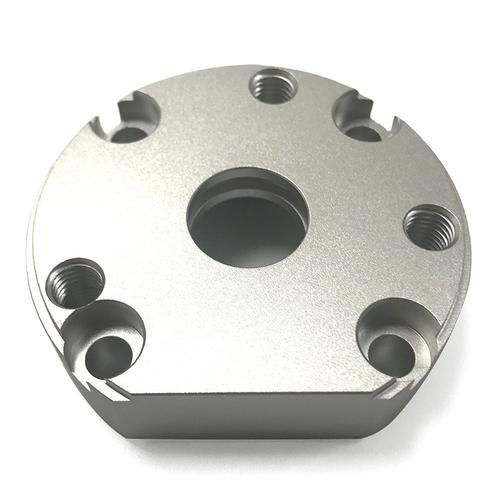
Metals
|
Aluminum Alloy 6061-T6, Titanium Alloy TC4
|
Strength testing, assembly verification (e.g., drone frames)
|
1. Cut into blanks 5-10mm larger than the design size; 2. Remove surface oxide layer with sandpaper
|
|
Engineering Plastics
|
ABS (Acrylonitrile-Butadiene-Styrene), PC (Polycarbonate)
|
Appearance simulation, lightweight testing (e.g., headphone housings)
|
1. Cut into regular blocks/sheets; 2. Wipe with alcohol to remove surface oil stains
|
|
Composite Materials
|
Carbon Fiber-Reinforced PC (CF-PC)
|
High-strength, lightweight needs (e.g., robot arms)
|
1. Cut along fiber direction (to avoid fiber breakage); 2. Apply protective film to prevent scratches
|
1.3 Design File Preparation and Verification
- File Format: Prioritize STEP/IGS (universal formats compatible with all CNC software); avoid STL (significant precision loss).
- Design Specifications:
-
- Minimum Wall Thickness: ≥0.5mm for metals, ≥1mm for plastics (to prevent machining breakage);
-
- Fillets/Chamfers: All sharp corners require R0.2-R0.5 fillets (to avoid tool chipping);
-
- Hole Depth Limit: Blind hole depth ≤4×hole diameter (e.g., ≤16mm for φ4mm holes, to prevent drill breakage).
- File Verification: Open the model in UG/NX software, run the “Geometry Check” function, and fix issues such as overlapping faces and non-closed edges.
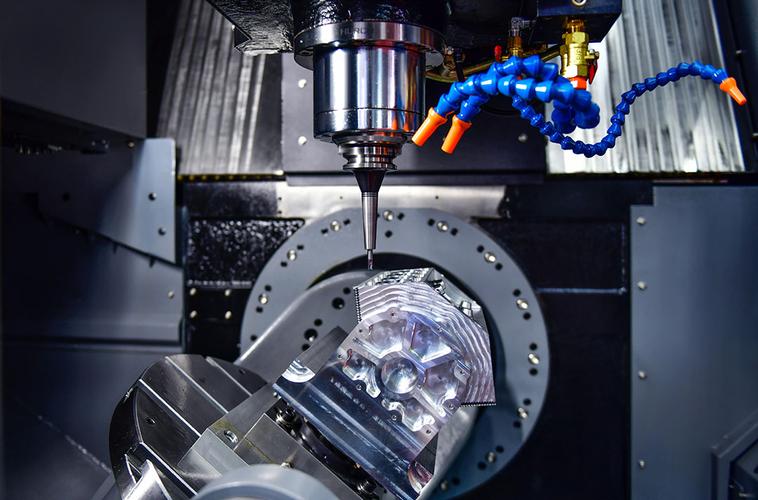
II. Core Steps: Step-by-Step Operation for CNC Prototype Manufacturing
2.1 Step 1: Design File Import and Programming (Critical Link)
- Import Model: Open the programming software, import the STEP file, and confirm the model coordinate system (default: model bottom surface as Z-axis zero point).
- Set Machining Strategies:
|
Machining Requirement
|
Recommended Strategy
|
Parameter Settings (Taking Aluminum Alloy 6061-T6 as Example)
|
|
Rough Milling (Material Removal)
|
Pocketing
|
Spindle speed 8,000 rpm, feed rate 1,500 mm/min, cutting depth 1mm
|
|
Finish Milling (Detail Refinement)
|
Contouring
|
Spindle speed 12,000 rpm, feed rate 800 mm/min, cutting depth 0.2mm
|
|
Drilling (φ4mm Hole)
|
Drilling Cycle
|
Spindle speed 5,000 rpm, feed rate 50 mm/min, peck drilling depth 2mm
|
- Simulation and Verification: Run the “Machining Simulation” function to check for tool path collisions (focus on the distance between the tool, fixture, and machine table). Generate G-code and save it to a USB drive.
2.2 Step 2: Material Clamping and Alignment (Precision-Critical)
- Clean the Worktable: Wipe the CNC machine table with alcohol to remove iron chips and oil stains, preventing clamping deviation.
- Clamp Materials:
-
- Metals: Secure with a precision vise, ensuring the material’s bottom surface is flush with the worktable (use a 0.1mm copper sheet for leveling if needed). Control the vise clamping force between 3,000-5,000N (excessive force causes material deformation).
-
- Plastics: Secure with a vacuum chuck (reserve a 10mm adsorption area on the material edge). Maintain a vacuum level ≥-0.08MPa.
- Machine Alignment:
-
- X/Y Axis Zero Positioning with Edge Finder (Accuracy ±0.001mm): Mount the edge finder on the spindle, manually move the spindle to touch the material edge, record coordinates, and set as zero.
-
- Z Axis Zero Positioning with Z-Setter: Place the setter on the material surface, lower the spindle until the setter alarms, and record the Z-axis coordinate (subtract the setter height, e.g., 10mm).
2.3 Step 3: Test Cutting Verification (Avoid Mass Scrap)
- Load Program: Insert the USB drive into the machine, call the G-code, and confirm the program number matches the machining path.
- Manual Override Adjustment: Set “feed rate override” and “spindle speed override” to 50%, then manually start the program.
- Test Cutting Observation:
-
- First 30 Seconds: Focus on whether the tool moves along the path (no collisions) and if the coolant system sprays normally (full coverage of the cutting area for metal machining).
-
- Pause After 10mm of Cutting: Use calipers to measure the test-cut area dimensions (e.g., contour size, hole diameter). If the error exceeds ±0.02mm, adjust programming parameters (e.g., reduce feed rate by 10%-20%, adjust cutting depth).
2.4 Step 4: Formal Machining (Real-Time Monitoring)
- Restore Overrides: Set “feed rate override” and “spindle speed override” to 100%, and start automatic machining mode.
- Real-Time Monitoring Key Points:
-
- Listen for Sounds: Normal machining produces a steady “rustling sound”; a “sharp squeal” indicates tool wear or excessive feed rate—pause immediately.
-
- Check Vibration: Spindle vibration amplitude should be ≤0.01mm (measure with a dial indicator close to the spindle). Excessive vibration requires checking tool tightness.
-
- Monitor Temperature: Spindle temperature ≤60℃ during metal machining (measure with an infrared thermometer). If exceeded, reduce spindle speed or increase coolant flow.
- Post-Machining: After the machine stops automatically, turn off the spindle and coolant system, then manually move the spindle to a safe position (away from the material).
2.5 Step 5: Post-Processing (Enhance Prototype Quality)
|
Material Type
|
Post-Processing Steps
|
Tools & Parameters
|
Quality Standards
|
|
Metals
|
1. Deburring: Remove edge burrs with a deburring tool; 2. Polishing: Sand the surface with 400# sandpaper, then refine with 800# sandpaper; 3. Rust Prevention: Anodize aluminum alloys (thickness 5-10μm)
|
Deburring tool angle 30°, anodizing temperature 20-25℃
|
Surface roughness Ra ≤0.8μm, no sharp burrs
|
|
Plastics
|
1. Deburring: Soften burrs with a heat gun (50-60℃) then scrape off; 2. Painting: Spray matte paint (thickness 20-30μm)
|
Heat gun speed level 2, painting distance 30cm
|
No runs or color differences; adhesion reaches Grade 5B (no peeling in cross-cut test)
|
|
Composite Materials
|
1. Deburring: Sand with carbon fiber-specific sandpaper (1000#); 2. Edge Sealing: Seal fiber cuts with epoxy resin
|
Sand along fiber direction, resin layer thickness 0.1mm
|
No exposed fibers, smooth edges without burrs
|
2.6 Step 6: Quality Inspection (Qualified Judgment)
- Dimensional Inspection:
-
- Critical Dimensions (e.g., assembly hole diameter, positioning pin height): Measure with CMM, error ≤±0.01mm.
-
- Non-Critical Dimensions (e.g., contours): Measure with digital calipers, error ≤±0.02mm.
- Appearance Inspection:
-
- Metal Prototypes: No scratches or dents; no anodized layer peeling.
-
- Plastic Prototypes: No bubbles or sink marks; no particles on the painted surface.
- Functional Inspection:
-
- Assembly Prototypes: Assemble with mating parts, gap ≤0.03mm (no jamming or looseness).
-
- Strength Prototypes: Conduct simple load tests (e.g., apply 500N pressure to aluminum alloy prototypes with no deformation).
III. Common Issues and Solutions
|
Issue Phenomenon
|
Possible Causes
|
Solutions
|
|
Machined dimensions too small (e.g., φ3.98mm for designed φ4mm hole)
|
Tool wear, excessive feed rate
|
1. Replace with a new tool; 2. Reduce feed rate by 10%-20%
|
|
Obvious tool marks on surface (Ra>1.6μm)
|
Low spindle speed, excessive cutting depth
|
1. Increase spindle speed by 2,000 rpm; 2. Reduce cutting depth to 0.1mm
|
|
Material deformation during machining (plastic bending, metal warping)
|
Excessive clamping force, insufficient cooling
|
1. Reduce clamping force by 1,000-2,000N; 2. Increase coolant flow
|
|
Tool breakage (especially for small hole machining)
|
Blind hole depth >4×diameter, no peck drilling program
|
1. Split deep hole machining (e.g., 10 pecks for 20mm deep holes); 2. Use extended tools (flute length ≥hole depth + 5mm)
|
IV. Safe Operation Specifications
- Personal Protection: Wear safety helmets, cut-resistant gloves, and safety goggles during machining (additional earplugs for metal machining to prevent noise damage).
- Equipment Maintenance: Check coolant level (must be between scale marks) and tool tightness (no looseness) before daily machining.
- Emergency Handling: In case of abnormalities (e.g., collisions, smoke), press the machine’s “emergency stop button” immediately, cut off power, and then inspect the fault.
V. Common CNC Machining Issues
- Abnormal Material Machining: When machining difficult-to-cut materials (e.g., titanium alloy), failure to use low-speed, high-cooling strategies leads to rapid tool wear and poor surface quality. For plastics, improper cutting parameters cause deformation and dimensional inaccuracies.
- Programming Parameter Errors: Mismatch between programming parameters and material properties (e.g., improper feed rate or cutting depth) causes cutting vibration and tool chipping, seriously affecting machining precision and efficiency.
- Missing Test Cutting: Skipping test cutting and proceeding directly to formal machining fails to identify programming or tool path issues in advance, leading to material waste and project delays.
- Inadequate Inspection: Neglecting real-time machining inspection and finished product testing may allow unqualified products to enter subsequent processes, failing to meet design and functional requirements.
- Speed-First Misconception: Overemphasizing machining speed while ignoring quality causes dimensional deviations and excessive surface roughness, increasing subsequent rework costs.
Disclaimer
- All information, opinions, and data contained in this article are for the purpose of information transmission only and do not constitute any advice on investment, transactions, law, medical care, or other matters.
- The content of the article is compiled based on public information or created based on the author’s personal understanding. Although every effort is made to ensure accuracy, it does not guarantee the completeness, accuracy, and timeliness of the information, nor does it bear any responsibility for any losses caused by the use of the content of this article.
- If the article involves third-party opinions, pictures, data, and other content, the copyright belongs to the original author. In case of infringement, please contact us for deletion.
- Readers should make independent decisions based on their actual situation and combined with professional opinions. The user shall bear all consequences arising from the use of the content of this article.

Name: Dr. Benjamin Keller
Nationality: Germany
Titles: Senior Research Scientist, Industrial Technology Consultant
Work Experience and Industry Qualifications:
An expert in the CNC field from Germany, with 25 years of in – depth industry experience. He has long focused on the high – precision optimization of five – axis linkage machining technology, the intelligent upgrade of AI – driven numerical control systems, and the practical application of digital twins in machining scenarios. He is particularly good at solving machining technical problems of complex surfaces in aerospace and precision components in the medical field. He is proficient in advanced programming of G – code and M – code, and is skilled in the debugging and optimization of mainstream numerical control systems such as Fanuc and Siemens. He can build an adaptive model of cutting parameters through machine learning algorithms, use virtual simulation tools to pre – rehearse the machining process and perform error compensation. At the same time, he has the ability to integrate multi – axis machining processes and additive manufacturing technologies, which can effectively improve machining efficiency and precision consistency.