I. Introduction
With the continuous increase in the demand for high – precision, high – reliability, and lightweight in the aerospace industry, CNC (Computer Numerical Control) technology has become the core support for aerospace parts manufacturing. Through digital programming and automated control, CNC technology has solved the problems of low efficiency and large errors in traditional processing, and has shown significant advantages especially in the processing of complex structural parts and high – performance materials. This article integrates the technical and data support of CNC parts in the aerospace field from dimensions such as technical advantages, application scenarios, key technologies, and future trends.
II. Core Advantages of CNC Technology in the Aerospace Field
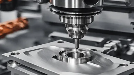
High – precision and Complex Geometry Machining Capability
CNC technology can achieve micron – level precision (usually up to ±0.005mm), meeting the processing requirements of complex curved surfaces of aerospace parts such as engine blades and fuselage skins. For example, spacecraft parts need to maintain performance in extreme temperature and radiation environments. CNC machining realizes the precision forming of high – strength alloys through multi – axis linkage (such as five – axis machine tools).
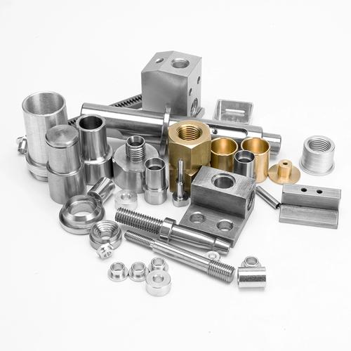
Efficient Production and Material Adaptability
CNC technology can process difficult – to – machine materials such as titanium alloys and nickel – based superalloys. Taking titanium alloy as an example, its cutting performance is optimal when the hardness range is HB 100 – 230. CNC significantly reduces tool wear and work – hardening problems by optimizing tool paths and cutting parameters (such as a rotation speed of 3000 – 6000rpm and a feed of 0.1 – 0.3mm/r).
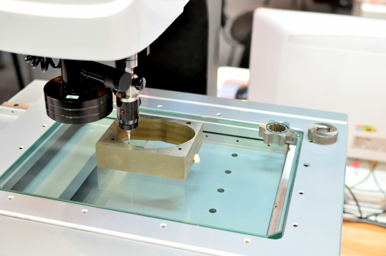
Automation and Quality Control
Combined with a fully automatic image measuring instrument (such as Tianxing measuring equipment), CNC technology can achieve real – time quality inspection, generate three – dimensional dimensional reports and statistical analysis, and reduce human errors. For example, the processing error of aerospace hydraulic housing parts can be controlled within 0.01mm through an automated detection system.
III. Typical Application Scenarios and Technical Data
Key Engine Components
Turbine Blades: Processed with ceramic tools (such as Si3N4 – based ceramics), the cutting speed can reach 200 – 400m/min, and the surface roughness Ra ≤ 0.4μm.
Combustion Chamber Parts: Through multi – process integrated processing (roughing allowance of 3 – 5mm, finishing allowance of 0.1 – 0.3mm), the number of clamping times is reduced, and the efficiency is increased by more than 30%.
Fuselage and Structural Parts
Integral Frame: Using high – speed milling technology (spindle speed ≥ 20,000rpm), the material removal rate can reach 500cm³/min when processing aluminum alloy fuselage skins.
Landing Gear Parts: Processing high – strength steel with carbide tools (WC – Co – based), the tool life is increased by 50%, and the processing cycle is shortened by 20%.
Avionics and Communication System Parts
For precision hole machining (hole diameter tolerance ±0.01mm), the drill – boring composite process is adopted, combined with CBN (cubic boron nitride) tools to achieve high – surface integrity.
IV. Key Technical Breakthroughs
Tool – Material Matching Technology
Tool Selection: For different materials, a gradient – matching strategy is adopted. For example, PCD (polycrystalline diamond) tools are preferred for titanium alloy processing, and CBN tools are used for superalloy processing.
Cutting Parameter Optimization: Predict cutting force and temperature based on finite – element simulation (such as Master CAM), and optimize the feed rate and cutting depth to avoid processing deformation.
Multi – axis Programming and Simulation Technology
Through five – axis linkage programming (such as the RTCP function), continuous processing of complex curved surfaces is realized, reducing the number of tool changes. For example, after the processing path of an aerospace part is optimized, the program length is reduced by 40%.
Virtual simulation technology (such as VERICUT) detects interference and over – cutting problems in advance, reducing the trial – cutting cost.
Intelligent Detection and Closed – loop Control
Integrate an on – line measurement system (such as a CNC imaging instrument), and the processing error is fed back in real – time and automatically compensated to ensure that the qualified rate of key dimensions is ≥ 99.5%.
V. Challenges and Solutions
Difficulty in Processing Materials
Problem: Titanium alloy has a low thermal conductivity (about 7W/m·K), which easily leads to tool thermal wear.
Solution: Adopt high – pressure cooling technology (pressure ≥ 10MPa), reducing the cutting temperature by more than 30%.
Clamping Difficulties for Complex Structures
Problem: Thin – walled parts are prone to deformation (such as wall thickness ≤ 1mm).
Solution: Design special fixtures (such as vacuum adsorption + elastic support), reducing the clamping force to 5 – 10N, and controlling the deformation within 0.02mm.
VI. Future Technical Trends
Intelligent and Adaptive Machining
An AI – based process parameter self – optimization system that can adjust cutting parameters in real – time, increasing efficiency by 15% – 20%.
Green Manufacturing and Energy – saving Technology
Develop low – energy – consumption CNC machine tools (with a 30% reduction in energy consumption), and promote dry cutting and minimum quantity lubrication technology.
Additive – Subtractive Hybrid Manufacturing
Combine 3D printing and CNC machining to achieve the integrated forming of complex internal cavity structures (such as fuel injectors).