Custom Thermoplastic Injection Molding Services
OEM Manufacturing for Engineering & High-Performance Plastic Components
From material selection and DFM to mold fabrication and mass production — one manufacturing partner for your entire thermoplastic component program.
Full-Service Injection Molding
In-house mold design, CNC/EDM tooling, injection molding, and secondary operations under one roof
Engineering to High-Performance Materials
ABS, PC, PA6/66, POM, PP, TPU, plus PEEK, PPS, PEI, and glass-filled grades
Tight-Tolerance Production
Mold tolerance ±0.02mm, part tolerance ±0.05mm; CMM inspection with full dimensional reports
Prototype to Mass Production
Single-cavity prototype tools through multi-cavity high-volume production; MOQ 1 pc for prototypes
Complete Secondary Operations
Ultrasonic welding, heat staking, pad printing, assembly, and custom packaging
Manufacturing Capabilities & Technical Specifications
Industry practice shows that suppliers with in-house tooling, engineering material experience, and robust quality systems deliver more consistent long-term results than price-only competitors. For high-melt resins like PEEK or PEI, we have the specialized equipment and experience to handle processing temperatures up to 400°C.
| Capability | Specification |
|---|---|
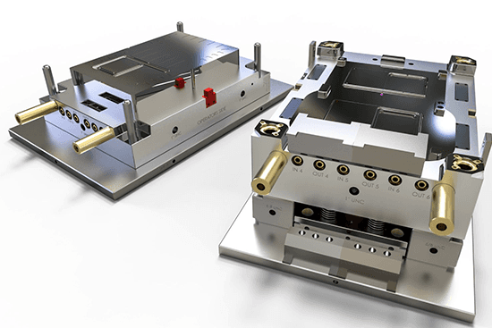
| Mold Making Process | CNC machining (3/4/5-axis), EDM, wire cutting, high-speed milling |
| Mold Tolerance | ±0.02mm (cavity); ±0.01mm (critical features) |
| Mold Material | P20, 718H, H13, NAK80, S136 (stainless for medical) |
| Mold Life (Estimated) | 300K–1M+ shots depending on mold steel grade and maintenance |
| Part Tolerance (Standard) | ±0.05mm |
| Part Tolerance (Precision) | ±0.02mm (geometry-dependent) |
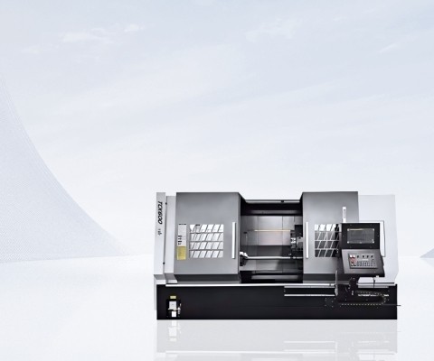
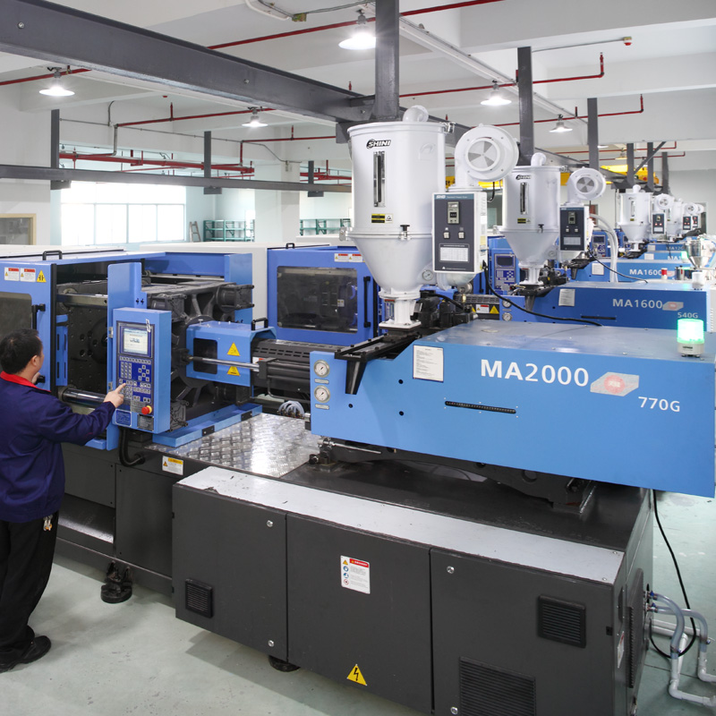
| Injection Machines | 80T–1000T clamping force range |
| Shot Size Range | 1g–3000g per shot |
| Surface Finishes | SPI A1/A2/A3, VDI 12–VDI 45 texture, mirror polish, EDM finish |
| Multi-Cavity Capability | Up to 64 cavities; family molds and hot runner systems available |
| Special Processes | Insert molding, overmolding, two-shot molding, gas-assisted molding, thin-wall molding |
| Quality Inspection | CMM, optical comparator, 2D vision measurement, surface roughness tester, thread gauge verification |
| Quality System | ISO 9001:2015 certified production environment |
| MOQ | 1 pc (prototype); flexible for production runs |
| Lead Time (Prototype Mold) | 10–15 working days |
| Lead Time (Production Mold) | 20–30 working days (complexity-dependent) |
| Lead Time (Production Parts) | 7–15 working days from mold approval |
| File Formats Accepted | STEP, IGES, SolidWorks, Parasolid, DWG, PDF, STL |
Thermoplastic Material Selection Guide
Material selection directly impacts part performance, mold design, and production costs. Below is our categorized guide to help you choose the right polymer for your application.
Commodity Thermoplastics
| Material | Key Properties | Typical Applications | Processing Notes |
|---|---|---|---|
| PP | Excellent chemical resistance, low density, good fatigue resistance, cost-effective | Living hinges, containers, automotive interior trim, consumer products | Semi-crystalline; wall thickness 1.5–4.0mm recommended; higher shrinkage (1.0–2.5%) requires mold compensation |
| PE | High impact strength, excellent moisture barrier, good low-temperature performance | Packaging, industrial containers, pipe fittings | Semi-crystalline; lower cost; available in HDPE (rigid) and LDPE (flexible) grades |
Engineering Thermoplastics
| Material | Tensile Strength | Key Properties | Typical Applications | Processing Notes |
|---|---|---|---|---|
| ABS | 30–50 MPa | Good impact resistance, dimensional stability, excellent surface finish | Electronic enclosures, automotive interior parts, appliance housings | Amorphous; shrinkage 0.4–0.7%; wall thickness 1.5–3.0mm recommended |
| PC | 55–75 MPa | Extreme impact resistance, optical clarity, high heat deflection | Safety goggles, medical device housings, automotive lenses | Amorphous; shrinkage 0.5–0.7%; requires drying before processing |
| PA6/PA66 | 60–80 MPa (unfilled) | High strength, wear resistance, good chemical resistance, excellent fatigue | Gears, bearings, automotive under-hood components, structural brackets | Semi-crystalline; shrinkage 1.0–2.0%; pre-drying critical for moisture control |
| POM | 60–70 MPa | High stiffness, low friction, excellent dimensional stability, good creep resistance | Precision gears, bearings, snap-fit assemblies, fuel system components | Semi-crystalline; wall thickness 2.0–4.0mm recommended; excellent machinability |
High-Performance Thermoplastics
| Material | Continuous Service Temp | Key Properties | Typical Applications | Processing Notes |
|---|---|---|---|---|
| PEEK | ~250°C | Exceptional chemical resistance, high strength-to-weight, steam sterilizable | Medical implants, aerospace components, semiconductor handling | Semi-crystalline; requires ~400°C processing temperatures and specialized equipment |
| PPS | ~200°C | Excellent chemical/heat resistance, inherent flame retardancy, good stability | Automotive under-hood components, electrical connectors, pump parts | Semi-crystalline; often glass-filled; requires high mold temperatures (130–150°C) |
| PEI (Ultem) | ~170°C | High strength, inherent flame retardancy, good chemical resistance | Medical device housings, aerospace interior components, electrical insulators | Amorphous; requires drying; high processing temperatures |
Key Selection Recommendations
- General parts: Prioritize ABS or PP for balanced cost and performance
- Transparent parts: Choose PC; for higher heat resistance, opt for PEI
- Precision gears/bearings: POM delivers low friction and stable dimensions for moving components
- High-temperature/chemical environments: Select PEEK, PPS, or PEI, and confirm your supplier has documented high-temperature processing experience
- High-strength parts: Glass-filled grades (e.g., PA66-GF30) boost rigidity and heat deflection, though note fiber orientation impacts shrinkage anisotropy
Thermoplastic vs Thermoset Molding — Key Differences
This is a common technical decision point for buyers. Below is an objective comparison to help you choose the right process for your project.
| Comparison Dimension | Thermoplastic Molding (Goldcattle) | Thermoset Molding |
|---|---|---|
| Reversibility | Can be reheated, remelted, and reshaped multiple times | Irreversible chemical crosslinking during curing; cannot be remelted |
| Cycle Time | Faster — part solidifies by cooling only | Slower — requires time for chemical curing reaction |
| Recyclability | Regrind can be reused (virgin material preferred for critical parts) | Not recyclable after curing |
| Temperature Resistance | Varies by material: PP 100°C, PEEK 250°C continuous | Generally higher continuous service temperature |
| Surface Finish | Excellent — wide range of SPI/VDI textures achievable | Good — but may require post-cure finishing |
| Common Materials | ABS, PC, PA, POM, PP, PE, PEEK, PPS, PEI | Epoxy, phenolic, melamine, silicone rubber |
| Best For | Mass production, recyclable products, complex geometries with fast cycles | Extreme heat environments, electrical insulation, heavy chemical resistance |
For most commercial injection molding applications, thermoplastic processing is the preferred choice due to its fast cycle times, recyclability, and design flexibility. Unless your part requires continuous exposure to temperatures above 250°C, thermoplastics typically offer a more cost-effective solution.
Industry Application Scenarios
Different industries have unique tolerance, documentation, and process control requirements. Our capabilities are structured to meet the specific standards of your sector.
| Industry | Typical Molded Parts | Key Requirements We Fulfill |
|---|---|---|
| Automotive & EV | Interior trim, under-hood connectors, sensor housings, EV battery components | PPAP Level 3 documentation, material certifications, serial traceability, high-volume production |
| Medical Devices | Diagnostic housings, surgical handles, disposable components, implantable parts | ISO 13485-aligned processes, biocompatible materials, cleanroom production, full lot traceability |
| Consumer Electronics | Device enclosures, wearable components, connector bodies, PCB covers | Cosmetic surface finish, tight dimensional fit, EMI/RFI shielding options, rapid prototyping |
| Industrial Equipment | Precision gears, valve bodies, pump components, seals, wear pads | Wear-resistant materials, tight tolerances on functional surfaces, high cycle life, chemical resistance |
| Aerospace & Defense | Lightweight structural brackets, avionics housings, interior cabin components | MIL spec material certifications, FAI documentation, flame-retardant grades, weight-optimized designs |
| Consumer Products | Appliance housings, furniture components, sports equipment parts, packaging | Cost-efficient production, aesthetic finishes, rapid scale-up from testing to full production |
Procurement Tip: Each industry has unique standards for tolerances, documentation, and certifications. When selecting a partner, confirm their deep understanding of your sector’s specific regulatory requirements.
Engineering Challenges & Proven Solutions
Injection molding can present recurring technical challenges. Below are the most common issues we resolve with our proven engineering solutions.
| Production Challenge | Root Cause | Our Proven Solution |
|---|---|---|
| Thin-Wall Filling Issues | Melt solidifies before cavity fills; high flow resistance | Higher injection speeds, dynamic mold heating, high MFI materials, conformal cooling |
| Shrinkage & Dimensional Control | Material shrinkage during cooling; differential cooling across sections | Material-specific cavity compensation, uniform wall thickness, balanced cooling, optimized packing pressure |
| Warpage / Part Distortion | Differential shrinkage, fiber orientation, residual stress | Uniform wall design, balanced gate placement, optimized cooling, CAE simulation to predict warpage |
| Sink Marks | Insufficient packing; thick sections cooling slower than walls | Rib/boss thickness ≤60% of wall, cored out thick sections, adequate packing pressure/time |
| Weld / Knit Lines | Material flow fronts meeting, creating weak points | Relocate gates to non-critical areas, increase mold/melt temperature, select materials with good knit strength |
| Flash | Insufficient clamping force, excessive pressure, worn parting surfaces | Clamping force calculation, optimized pressure profile, regular mold maintenance |
| Material Degradation | Overheating, excessive residence time, contamination | Material-specific temperature profiling, purge protocols, virgin material for critical parts |
| Surface Blemishes | Inconsistent flow, moisture, mold contamination | Proper material drying, cavity polishing, optimized injection speed and mold temperature |
Research shows ~70% of molding defects stem from improper plasticization and injection parameters, while 68% relate to poor gating system design. We resolve these risks before tool fabrication through CAE simulation and DFM review.
Our Thermoplastic Molding Process
From engineering drawings to final part delivery, our 8-step standardized process ensures consistency and traceability for every project.
CAD File & Specification Review
We review your 3D files and requirements, completing initial feasibility assessment within 24 hours.
DFM Analysis
Our team evaluates manufacturability, providing detailed DFM feedback and design suggestions within 48 hours.
Mold Flow Simulation (CAE)
We use CAE software to predict filling behavior and resolve shrinkage/warpage risks before tooling.
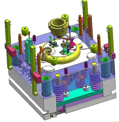
Mold Tooling Manufacturing
CNC, EDM, and wire cutting build your mold, with precision tolerances down to ±0.02mm.
T1 Sample Production & Validation
First article samples are produced and tested, with full CMM reports delivered for your approval.
Mold Adjustment & Optimization
We refine the mold and parameters based on T1 results, targeting a zero-defect production state.
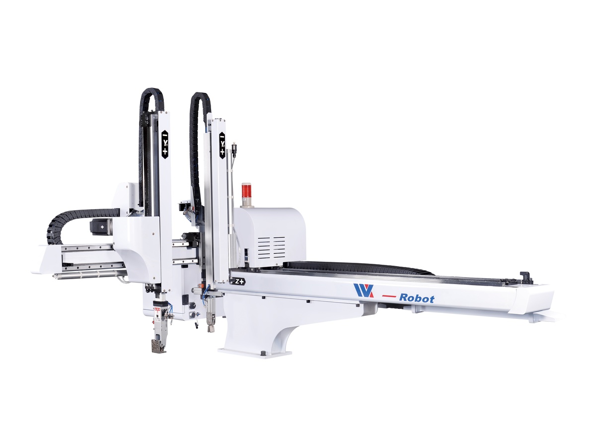
Production Injection Molding
Batch production with closed-loop control of critical parameters, ensuring consistency across runs.
Final Inspection & Global Delivery
100% critical dimension inspection, with material certificates and global shipping to your location.
DFM Guidelines for Injection Molded Parts
Optimizing your part design can significantly reduce mold costs, shorten lead times, and improve part quality. Below are our engineering team’s proven guidelines.
Wall Thickness Guidelines
| Material Family | Recommended Nominal Wall | Minimum Wall | Notes |
|---|---|---|---|
| ABS / PC (Amorphous) | 1.5–3.0 mm | 0.8 mm | Good stiffness/cosmetic balance; short cooling time |
| PP / PE (Semi-crystalline) | 1.5–4.0 mm | 0.6 mm | Higher shrinkage, thicker sections tolerated |
| POM (Acetal) | 2.0–4.0 mm | 1.0 mm | Requires thicker sections for strength |
| PA6/PA66 (Nylon) | 1.5–4.0 mm | 0.8 mm | Glass-filled grades may allow thinner walls |
| PEEK / PPS (High-Performance) | 1.5–3.0 mm | 0.6 mm | Thin-wall possible but requires specialized processing |
Core Design Principles
- Uniform Wall Thickness: The first rule of injection molding. Sudden changes cause uneven cooling, shrinkage, and warpage. Ribs for rigidity should be 40–60% of adjacent wall thickness, with height limited to 2–3x wall thickness.
- Draft Angle: Minimum 1° per side for smooth surfaces; add 1° per 0.025mm of texture depth. We recommend 1.5–2° for reliable demolding.
- Internal Corner Radii: Minimum R0.5mm. Ideal is 50–75% of wall thickness, to reduce stress concentration and improve material flow. Avoid sharp internal corners.
- Rib & Boss Design: Boss wall thickness should be ~60% of adjacent wall, with height no more than 2–3x diameter. Root radii are critical to avoid stress points.
Additional DFM Tips
- Place gates in the thickest wall area, avoiding cosmetic impact on functional surfaces
- Only use tight tolerances on critical functional features — over-tolerancing multiplies inspection and production costs
- Position parting lines along non-visual surfaces or natural edges to reduce post-processing
- Submit STEP/IGES files for accurate DFM analysis, with 2D drawings marking critical dimensions
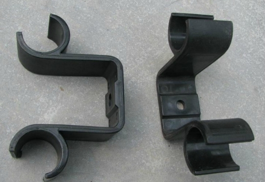
Case Study — Automotive-Grade Thermoplastic Housing
| Industry | Automotive Tier-1 Supplier |
| Material | PA66 GF30 (30% Glass-Filled Nylon 66) |
| Part Function | Engine compartment sensor housing |
| Key Requirements | Heat resistance to 150°C, chemical resistance to engine fluids, ±0.05mm tolerance on connector interface |
| Mold Type | 2-cavity production mold with hot runner system |
| Mold Material | H13 steel (1.2344) with hardened cavities |
| Key Challenge | Differential shrinkage from fiber orientation causing initial 0.8mm warpage across the 120mm housing |
| Solution Applied | Moldflow simulation, optimized gate location, cooling channel redesign, packing pressure profiling |
| Final Tolerance Achieved | ±0.04mm on critical features; warpage reduced to 0.2mm (within specification) |
| Quality Documentation | PPAP Level 3 with full CMM report, material certification, Cpk >1.67 process capability |
| Production Volume | Initial batch: 10,000 units; ongoing annual volume: 80,000+ units |
| Lead Time | 25 working days from drawing approval to T1 samples |
Result: We achieved a 98% first article pass rate. The client approved mass production within two weeks of receiving T1 samples, and later added two additional derivative sensor housing mold contracts.
Buyer’s Guide — How to Select a Thermoplastic Molding Partner
Choosing the right manufacturing partner is critical to ensuring product quality, reducing supply chain risk, and maintaining long-term cost control. Here are the key dimensions to evaluate:
1. Material Expertise
Confirm your supplier has documented mass production experience with your target material. For high-performance polymers, look for proven case studies, not just equipment lists.
2. Tooling Strategy & DFM Capabilities
Evaluate in-house mold making capabilities, 48-hour DFM feedback, and CAE/Moldflow simulation to avoid defects before tool fabrication.
3. Quality Systems & Inspection
Verify they can provide CMM reports, material certifications, FAI reports, and industry-specific certifications like IATF 16949 or ISO 13485 as needed.
4. Production Scalability
Confirm they can support your growth from prototype to mass production without quality gaps. Look for ≥95% on-time delivery and >50% repeat order rate.
5. Vertical Integration
In-house tooling, secondary operations, and assembly reduce outsourcing dependency, shorten lead times, and improve quality control.
6. Communication & Responsiveness
1–2 hour response times are a sign of operational discipline. Delays during quoting often correlate with poor update frequency during production.
Frequently Asked Questions
What is thermoplastic molding?
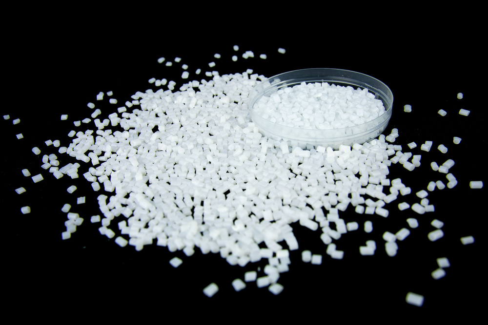
Thermoplastic molding is a manufacturing process where thermoplastic resin pellets are heated to a molten state and injected under high pressure into a precision steel mold cavity. The material cools and solidifies into your final part shape. Unlike thermosets, thermoplastics can be reheated and reshaped multiple times without irreversible chemical change.
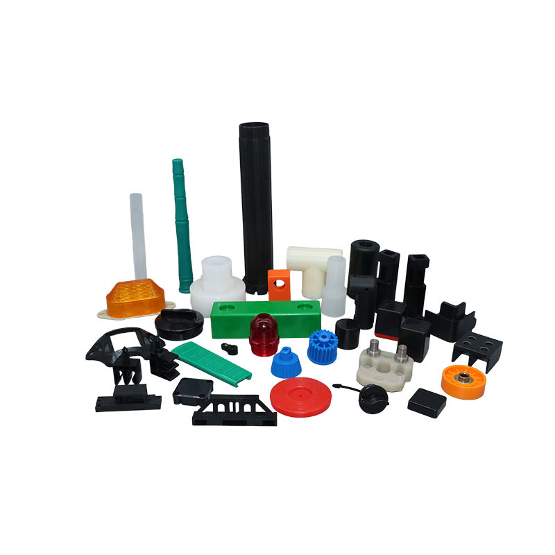
What thermoplastic materials do you mold?
We work with commodity plastics (PP, PE), engineering thermoplastics (ABS, PC, PA6/PA66, POM), and high-performance polymers (PEEK, PPS, PEI). We also process glass-filled, mineral-filled, and fiber-reinforced grades. See our Material Selection Guide above for detailed property data.
What is the difference between thermoplastic and thermoset molding?
Thermoplastics can be reheated, remelted, and reshaped multiple times, solidifying only through cooling. Thermosets undergo irreversible chemical crosslinking during curing and cannot be remelted. Thermoplastics generally offer faster cycle times and full recyclability.
What tolerances can you hold on injection molded parts?
Our standard part tolerance is ±0.05mm. Precision features can be held to ±0.02mm depending on part geometry and material. Mold cavity tolerance is ±0.02mm, and we provide full CMM dimensional reports with every production batch.
Can you support low-volume molding projects?
Yes. We offer prototype molds for volumes as low as 1–100 pieces, and bridge tooling for pre-production volumes (500–5,000 pieces) before you commit to full-scale multi-cavity production tools.
How do you control shrinkage and warpage?
We address these issues through multiple layers of control: material-specific cavity compensation, uniform wall thickness design, balanced cooling channel layout, optimized process parameters, and CAE simulation to validate designs before fabrication.
What is your typical lead time for new projects?
Prototype mold lead time is 10–15 working days. Production mold lead time is 20–30 working days, depending on complexity. Production parts take 7–15 working days from mold approval. Times may vary based on current production schedule.
Ready to Start Your Project?
Send us the following information to get started, or submit via our secure quote form:
- 3D CAD files — STEP or IGES preferred; PDF drawings with critical dimensions are also acceptable
- Material requirements — specify the grade, or describe your application and we will recommend the best option
- Target quantity — prototype, low-volume, or mass production
- Surface finish requirements — SPI grade, VDI texture code, or functional description
- Critical tolerances and functional features — mark your key mating interfaces
- Industry/application — to help us plan process controls to meet your sector’s standards
Our Quote Process
- Initial feasibility assessment within 24 hours
- Detailed DFM feedback and design optimization suggestions within 48 hours
- Transparent formal quote for mold cost, part unit price, and lead time
- Mold fabrication begins after design approval
- T1 samples delivered with full CMM dimensional report
- Mass production starts immediately after sample approval
All inquiries receive a response within one business day. No CAD files? Send us sketches, reference images, or basic dimensions, and our engineering team will help you build the 3D model.