- Answer
The five core steps in the milling process usually include: programming and program preparation, workpiece clamping and positioning, tool setting and coordinate system establishment, automatic machining execution, machining inspection and post – processing. - Extended Answer
I. Programming and Program Preparation - Step Definition
By writing numerical control programs (G – code / M – code), the tool movement trajectory, cutting parameters, and auxiliary actions are set. This is the digital foundation of milling processing. - Key Contents
Programming Methods:
Manual Programming: Suitable for simple contours (such as straight lines and arcs), directly write G – codes (e.g., G01 for linear interpolation, G02 for clockwise arc).
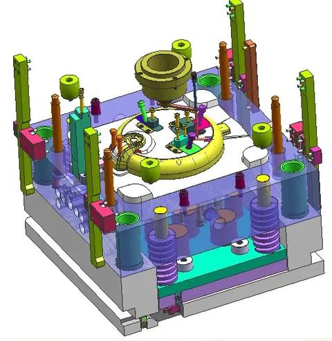
Automatic Programming: With the help of CAD/CAM software (such as UG, Mastercam), generate tool paths automatically through 3D models, and then post – process them into numerical control programs. It is suitable for complex curved surfaces (such as mold cavities and impellers).
Program Composition:
Program Header: Includes the program number (e.g., O0001) and the setting of the machine tool coordinate system (G90 for absolute coordinates).
Processing Instructions: Cutting parameters (S for spindle speed, F for feed rate), tool paths (G00 for rapid movement, G03 for counter – clockwise arc).
Program Tail: End instruction (M30 for program end and reset).
Precautions: The correctness of the program needs to be verified (e.g., simulate cutting through simulation software) to avoid over – cutting, under – cutting, or tool collision.
II. Workpiece Clamping and Positioning - Step Definition
Fix the workpiece on the machine tool worktable to ensure its stable position during processing and avoid vibration or displacement. - Key Contents
Clamping Principles:
Six – point positioning principle: Restrict the six degrees of freedom of the workpiece (movement and rotation in the X/Y/Z axes), for example, achieved through a vise, clamps, or special fixtures.
Unified datum: The clamping datum is consistent with the design datum and programming datum to reduce positioning errors.
Common Fixtures:
Vise: Suitable for small and medium – sized regular workpieces (such as rectangular plates), and the perpendicularity of the vise jaws needs to be corrected.
Clamp Bolts: Used for large workpieces or blanks, fixed by clamps and bolts, and attention should be paid to the uniform clamping force.
Magnetic Worktable: For magnetic – conductive materials (such as steel parts), fixed by electromagnetic adsorption, with high clamping efficiency.
Clamping Key Points:
The overhanging amount of the workpiece should not be too large to avoid vibration during cutting;
The surface of the blank needs to be cleaned to prevent impurities from affecting the positioning accuracy;
For thin – walled parts, additional support should be added to prevent clamping deformation.
III. Tool Setting and Coordinate System Establishment - Step Definition
Determine the relative position between the tool and the workpiece, and establish the workpiece coordinate system (G54 – G59) to provide a coordinate reference for program execution. - Key Contents
Purpose of Tool Setting:
Determine the starting position (tool setting point) of the tool in the machine tool coordinate system, so that the program coordinates match the actual processing position.
Tool Setting Methods:
Mechanical Tool Setting: Use the trial – cutting method or a tool – setting block to contact the workpiece surface, record the machine tool coordinates and input them into the system (e.g., when setting the X – axis, the tool lightly touches the left side of the workpiece and is set as X0).
Electronic Tool Presetter: Measure the distance from the tool to the workpiece through a sensor and automatically calculate the coordinate offset, with an accuracy of up to ±0.01mm.
Optical Tool Setting: Use the optical system (such as laser tool setting) 自带 by the machine tool to quickly position the tool.
Coordinate System Establishment:
The origin of the commonly used workpiece coordinate system (G54) is usually set at the upper – left corner, center, or reference hole position of the workpiece, and it needs to be consistent with the coordinate system in programming.
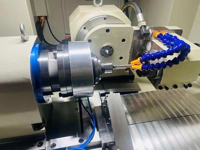
IV. Automatic Machining Execution - Step Definition
The machine tool runs automatically according to the program instructions, and the tool cuts the workpiece along the predetermined trajectory to complete material removal. - Key Contents
Selection of Cutting Parameters:
Spindle Speed (S): Depends on the material hardness and tool diameter. For example, when using high – speed steel tools for aluminum alloys, S = 1000 – 2000r/min, and when using carbide tools to process steel, S = 3000 – 5000r/min.
Feed Rate (F): Affects the surface roughness. For finishing, F = 50 – 200mm/min, and for roughing, F = 200 – 500mm/min.
Depth of Cut (ap): In roughing, it takes 1/3 – 1/2 of the tool diameter (e.g., for a Φ10mm end – mill, ap = 3 – 5mm), and in finishing, ap ≤ 0.5mm.
Processing Strategies:
Up – milling and Down – milling:
Down – milling: The direction of tool rotation is the same as the feed direction, suitable for finishing (smooth surface), but the machine tool needs to eliminate the lead – screw clearance;
Up – milling: The directions are opposite, suitable for roughing (impact – resistant), but the tool wears faster.
Layer – by – layer Cutting: In deep – cavity processing, cut layer by layer (each layer ap = 0.5 – 2mm) to avoid tool overload.
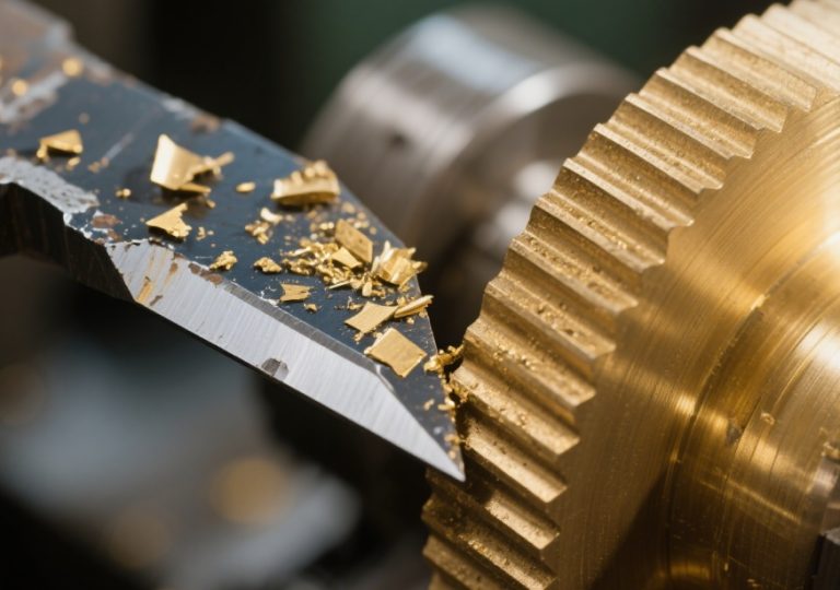
Processing Monitoring:
Observe the cutting state (the color and shape of the chips: silver – white chips are normal for steel parts, and blue indicates overheating);
Listen to the machine tool sound (abnormal noise may indicate tool wear or interference);
Adjust parameters in real – time (e.g., reduce the feed rate in case of vibration).
V. Machining Inspection and Post – processing - Step Definition
Inspect the dimensions and geometric tolerances of the machined workpiece, and adjust the process according to the results or complete post – processing (such as deburring, cleaning). - Key Contents
Inspection Tools and Methods:
Dimension Inspection:
Vernier Caliper (accuracy 0.02mm): Measure length and hole diameter;
Micrometer (accuracy 0.01mm): Measure shaft diameter and wall thickness;
Coordinate Measuring Machine (CMM): Detect the contour and position of complex curved surfaces (accuracy ±0.005mm).
Geometric Tolerance Inspection:
Dial Indicator: Detect flatness and perpendicularity (such as the deviation between the workpiece surface and the reference surface);
Plug Gauge: Check whether the inner hole size is qualified.
Inspection Standards:
Compare with the requirements of the part drawing to determine whether the dimensions (such as hole diameter Φ10±0.05mm) and surface roughness (such as Ra1.6) meet the standards.
Post – processing and Correction:
Qualified parts: Deburr, clean, and perform anti – rust treatment;
Unqualified parts: Analyze the reasons (such as programming errors, tool – setting deviations), re – machine or scrap;
Data Record: Save the inspection results for process optimization (such as adjusting cutting parameters to improve the qualification rate).
Extended Supplementary: Expansion Points of Milling Technology
Influence of Tool Selection: End – mills are suitable for planes and contours, ball – nose mills for curved surfaces, and keyway mills for slot – like structures;
Material Adaptability: Steel parts need cooling and lubrication, and aluminum alloys need to prevent tool sticking (use high – speed cutting + kerosene cooling);
Automation Trend: In some production lines, truss robots are used for automatic loading and unloading to achieve unmanned milling processes.
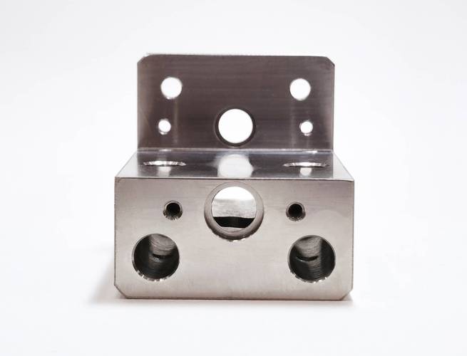
Through the systematic implementation of the above five steps, milling processing can efficiently and accurately transform from design to finished products, and is widely used in fields such as aerospace, automotive manufacturing, and mold processing.