Cracking in injection molded parts is primarily caused by internal stresses exceeding material strength limits, typically resulting from uneven cooling, improper process parameters, design flaws, material issues, or environmental factors that create stress concentration points.
Types of Injection Molding Cracks
|
Crack Type
|
Appearance
|
Common Causes
|
Typical Locations
|
|
Stress Cracks
|
Radiating from stress points
|
Internal stress, design flaws
|
Gate area, corners
|
|
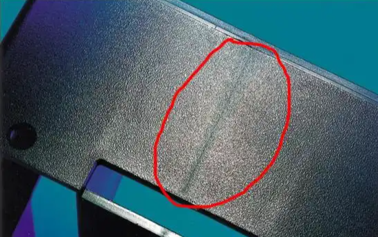
Flow Marks Cracks
|
Along flow direction
|
Melt flow issues
|
Flow path, thin sections
|
|
Weld Line Cracks
|
At material joining lines
|
Poor weld quality
|
Material junctions
|
|
Environmental Cracks
|
Surface crazing
|
Chemical attack, aging
|
Exposed surfaces
|
Distribution of Cracking Causes

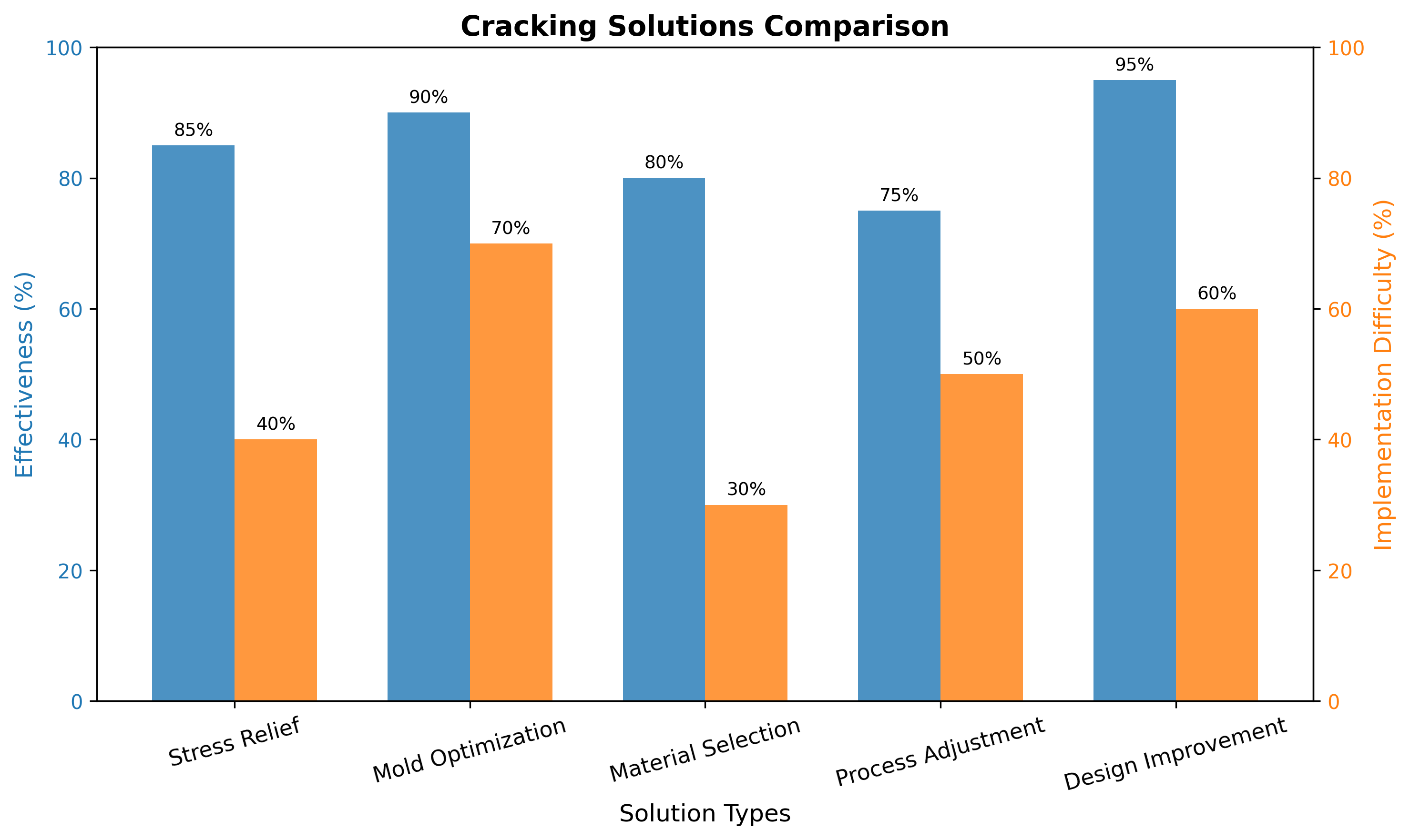
Cracking Solutions Comparison
Professional Knowledge about Injection Molding Cracking
Internal Stress Mechanisms
- Orientation Stress: Molecule alignment during flow, frozen by rapid cooling
- Shrinkage Stress: Uneven cooling rates between thick and thin sections
- Thermal Stress: Temperature gradients creating expansion/contraction differences
- Assembly Stress: External forces during post-molding processing
Material-Related Factors
- Residual Moisture: Hydrolysis weakens molecular structure, especially in PA, PC, PET
- Material Degradation: Overheating causes chain scission and brittleness
- Recycled Material Content: Excessive regrind (>30%) reduces impact strength
- Filler Content: High glass fiber loading increases brittleness and stress concentration
Process Parameter Issues
- Injection Pressure: Excessive pressure increases internal stress
- Temperature Control: Melt temperature too high causes degradation; too low increases shear stress
- Cooling Rate: Rapid cooling freezes molecules in stressed state
- Screw Parameters: High speed/low back pressure causes uneven plasticization
Design and Mold Factors
- Wall Thickness: Abrupt changes (>30% difference) create stress concentration
- Sharp Corners: Radius <0.5×wall thickness acts as stress riser
- Draft Angles: Insufficient draft (<1°) increases ejection stress
- Gate Design: Improper location/size concentrates stress at gate area
Environmental Factors
- Chemical Exposure: Solvents, oils, and cleaning agents cause environmental stress cracking
- Temperature Extremes: Thermal cycling accelerates crack propagation
- Humidity: Moisture absorption weakens hygroscopic materials over time
Frequently Asked Questions (FAQ)
Q1: How can I identify the root cause of cracks?
A: Analyze crack location, direction, and timing. Gate area cracks indicate process issues; corner cracks suggest design flaws; delayed cracking points to environmental factors.
Q2: What is the most effective way to reduce internal stress?
A: Use annealing heat treatment at Tg-10°C to Tg+10°C (e.g., PC at 125°C) for 10-15 minutes per mm thickness, followed by slow cooling.
Q3: How should I design corners to prevent cracking?
A: Use minimum radius of 0.5×wall thickness, with 1×wall thickness preferred for high-stress applications.
Q4: What process parameters should I adjust first for cracking?
A: Reduce injection pressure, increase mold temperature, optimize cooling time, and ensure proper material drying.
Q5: Can mold design prevent cracking?
A: Yes. Ensure adequate draft angles, proper gate placement, uniform wall thickness, and balanced ejection system.
Q6: How does material selection affect cracking resistance?
A: Choose materials with higher impact strength and lower stress sensitivity. Avoid highly crystalline materials for complex parts.
Q7: What is environmental stress cracking?
A: Cracking caused by chemical exposure (solvents, oils) that reduces material strength and lowers the stress required for fracture.
Q8: How can I test for residual stress?
A: Use polarized light inspection, solvent immersion testing, or stress measurement equipment to quantify stress levels.
Disclaimer
All experimental data presented in this paper are derived from controlled production environments and standardized test procedures. However, due to differences in equipment models, material batches, and on-site operating conditions, readers are advised to verify and adjust technical parameters according to their specific application scenarios before practical implementation.
The research results and technical insights shared herein are based on the author’s professional experience and experimental observations. The author and the affiliated institution shall not be liable for any direct, indirect, or consequential damages (including but not limited to equipment damage, product quality issues, or production losses) arising from the improper use of the information provided in this paper.