Contour Milling Technology – Complete Guide
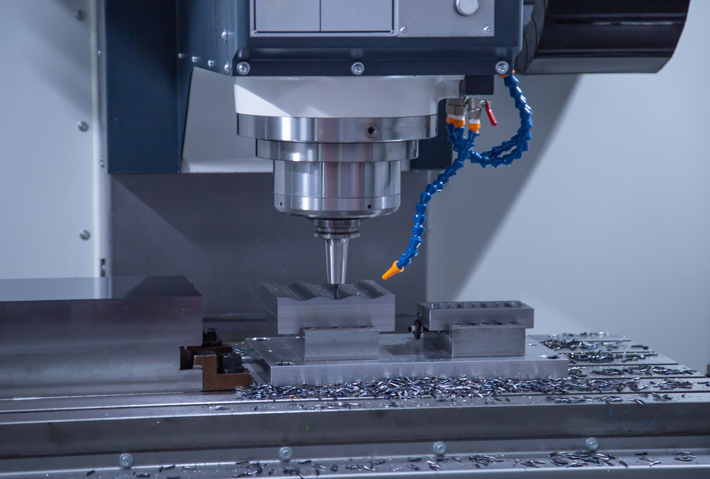
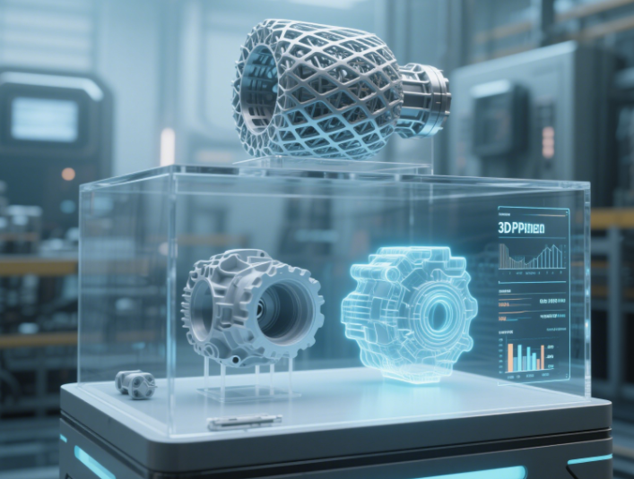
High precision CNC milling machine performing contour milling operation
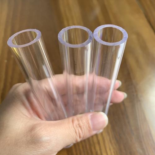
What is Contour Milling?
Contour milling is a specialized machining process that uses Computer Numerical Control (CNC) machine tools to create precise contours or surfaces on workpieces made of metals, plastics, composites, and other materials. It enables the production of complex geometric shapes, sectional transitions, and smooth surface finishes.
Widely applied in industries with stringent requirements for precision and surface quality such as aerospace, automotive manufacturing, and medical devices, contour milling efficiently addresses the challenges of high-precision, complex designs, and cost-effective production.
Core Technical Features
- High Precision Control: Achieves ±0.01mm level machining accuracy
- Complex Shape Machining: Capable of processing 2D and 3D complex contours
- Excellent Surface Quality: Surface roughness can reach below Ra 0.8μm
- Strong Material Adaptability: Supports processing of various metals and non-metals
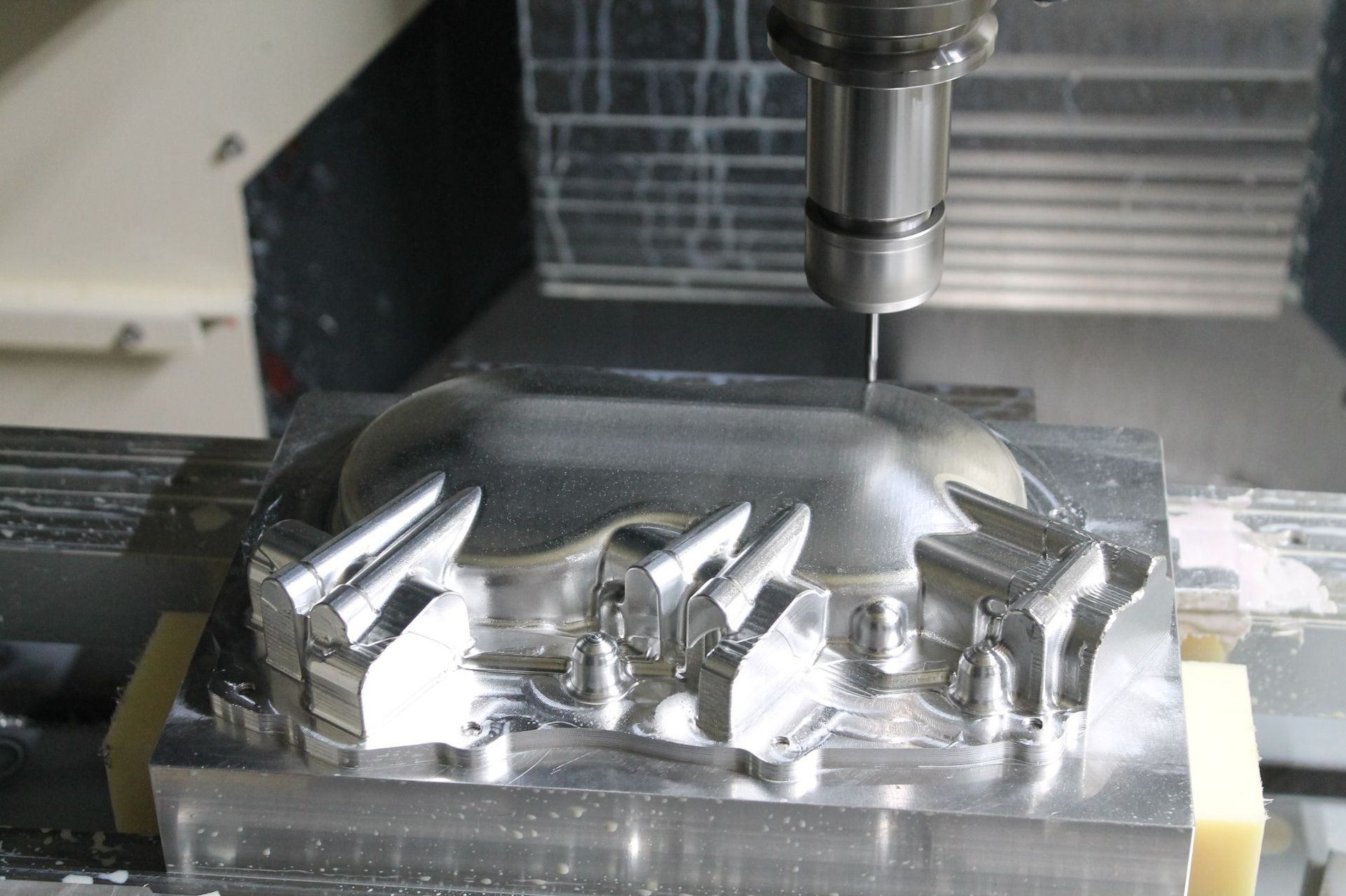
Contour Milling Techniques and Processes
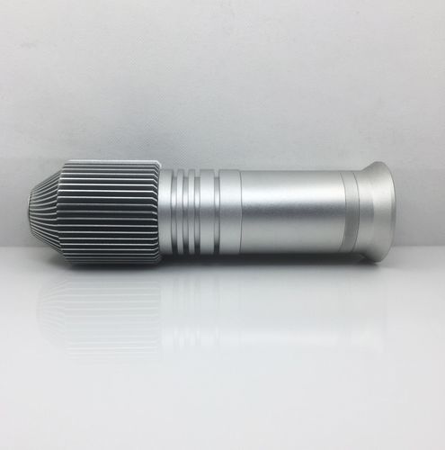
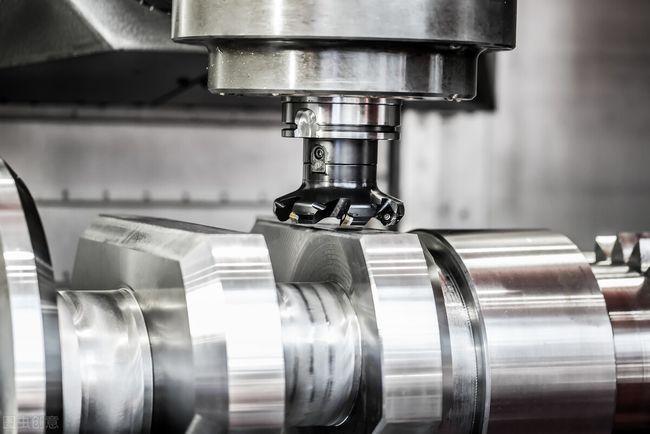
Precision contour milling of complex metal components
2D vs 3D Contour Milling
2D Contour Milling
- Relatively low cost, suitable for planar or limited depth designs
- Simple process, cost-effective, and efficient
- Mainly used for basic contours and pocket machining
3D Contour Milling
- Can machine deep cavities and fine surfaces
- Realizes complex 3D geometric shapes
- Suitable for aerospace parts, molds, and complex designs
Climb Milling vs Conventional Milling
Climb Milling
The rotation direction of the cutting tool is the same as the feed direction, ensuring excellent surface finish and reducing tool wear. Suitable for processing scenarios requiring high surface finish.
Conventional Milling
The rotation direction of the cutting tool is opposite to the feed direction. May cause more vibration and surface finish defects, but suitable for rough machining and older machines.
High-Speed Machining Technology
High-speed machining improves productivity by increasing cutting speed. It offers advantages such as increased feed rates, shortened cycle times, improved surface finish, and reduced tool wear. However, it requires more advanced CNC machining equipment and special cutting tools to handle the stress and thermal conditions during operation.
Suitable Materials and Tool Selection
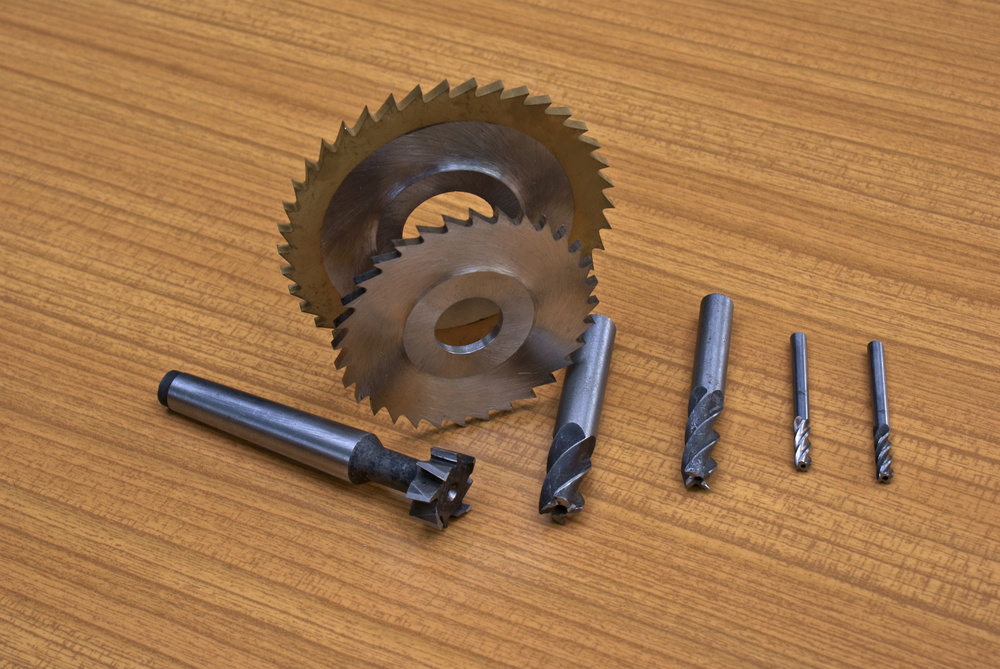
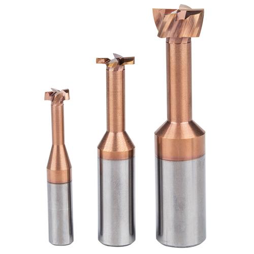
Various cutting tools used in contour milling operations
Metallic Materials
- Titanium Alloys: High hardness, requires low-speed cutting, suitable for aerospace applications
- Stainless Steel: High hardness, requires low-speed cutting, excellent corrosion resistance
- Aluminum Alloys: Can be processed at high speeds, lightweight, widely applied
- Copper Alloys: Good thermal conductivity, suitable for precision electronic components
Non-Metallic Materials
- Engineering Plastics: ABS, POM, PEEK, etc.
- Composite Materials: Carbon fiber, glass fiber reinforced materials
- Ceramic Materials: High hardness, requires special processing techniques
Cutting Tool Material Selection
Carbide Tools
High wear resistance, suitable for high-speed machining of hard materials
HSS Tools
Cost-effective, flexible, suitable for general-purpose machining
Ceramic Tools
Heat-resistant, suitable for precision machining of hard materials
Contour Milling Process Flow
Rough Machining
Uses large milling cutters or roughing inserts to aggressively remove most of the material, forming the approximate shape of the part, leaving 1 to 3 millimeters of material for subsequent processing. This is a necessary step for mass-producing large and complex features.
Semi-Finishing
Uses small tools to remove the remaining material from rough machining, shapes the workpiece, enhances surface quality, and prepares for finishing.
Finishing
Uses tools with fine cutting edges to remove the last bit of material, achieving the final surface quality and ensuring the geometric shape and dimensional accuracy of the part. This is particularly crucial under strict tolerance conditions.
Super-Finishing
Goes beyond conventional finishing to achieve ultra-smooth surfaces and extremely fine tolerances. Used in fields with extremely high requirements for surface finish, such as aerospace and precision medical devices, using special tools to obtain mirror-like finishes.
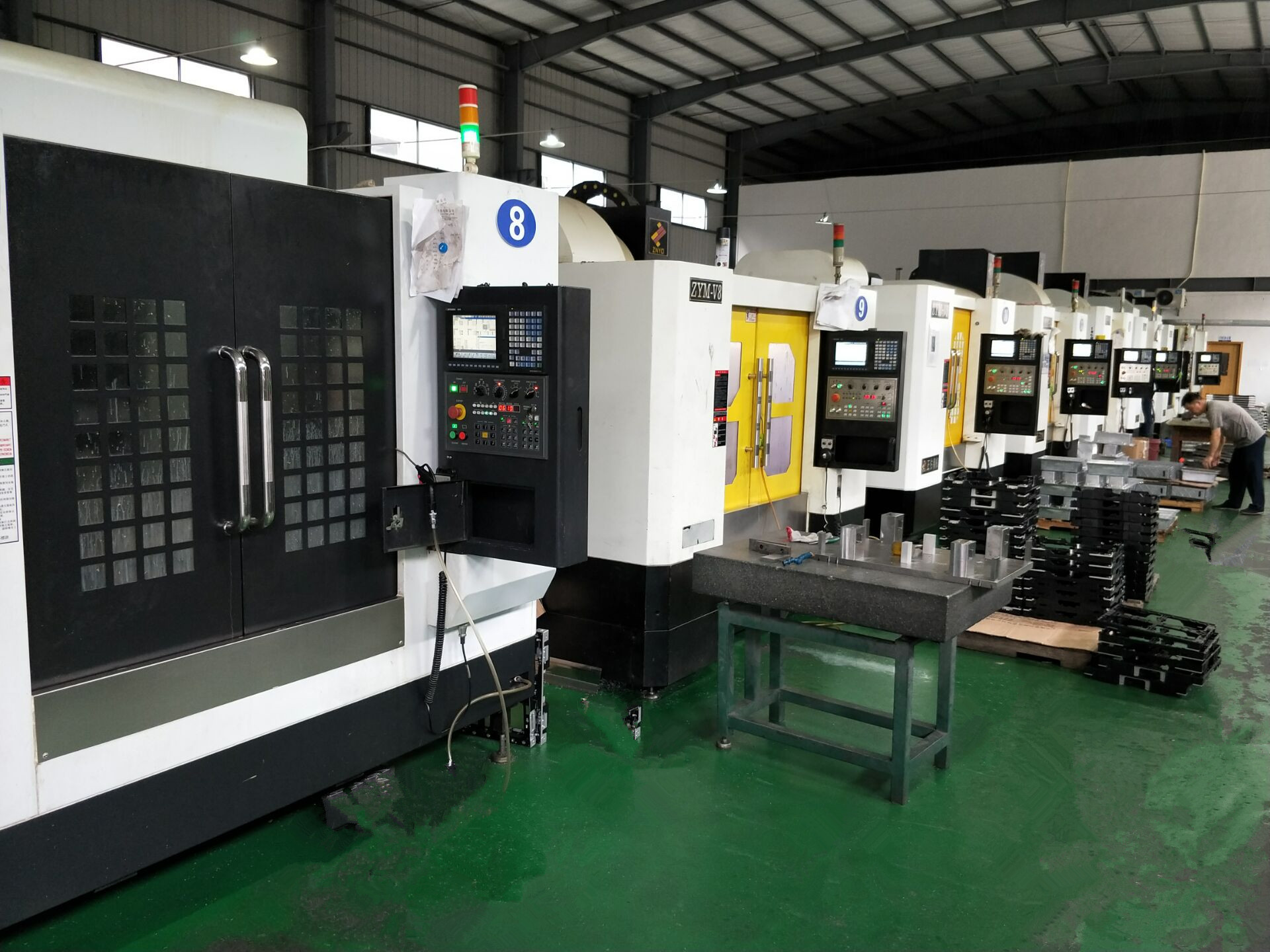
Application Fields
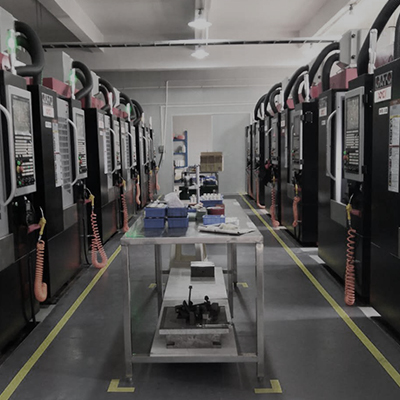
Modern precision machining workshop with advanced CNC equipment
Aerospace Industry
- Complex turbine blades
- Structural components
- Heat shields and other critical parts
These parts require complex details and strict tolerances
Automotive Industry
- Engine blocks and cylinder heads
- Transmission components
- Brake system components
Leveraging its high-speed and high-precision characteristics
Mold Manufacturing
- Injection molds
- Stamping dies
- Die casting molds
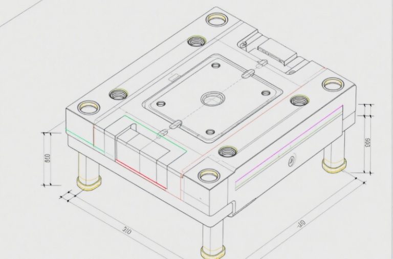
Tools for shaping complex objects
Medical Devices
- Surgical instruments
- Implants and prosthetics
- Diagnostic equipment components
Require high precision and excellent surface finish
Experimental Test Data
* The data is for reference only. The actual processing effect may vary due to differences in equipment, materials, and process parameters.
Surface Roughness Test Results
| Material Type | Climb Milling Ra (μm) | Conventional Milling Ra (μm) |
|---|---|---|
| Aluminum Alloy 6061 | 0.42 | 0.68 |
| Stainless Steel 304 | 0.58 | 0.85 |
| Titanium Alloy Ti-6Al-4V | 0.75 | 1.02 |
Machining Accuracy Test
| Machining Feature | Target Dimension (mm) | Actual Dimension (mm) | Error (μm) |
|---|---|---|---|
| Hole Diameter | 10.000 | 10.002 | +2 |
| Flatness | 0.010 | 0.008 | -2 |
| Perpendicularity | 90.00° | 89.98° | -0.02° |
Process Parameter Optimization Experiment
Effect of Spindle Speed on Surface Quality
Experimental Conditions: Aluminum Alloy 6061, Feed Rate 100mm/min, Cutting Depth 0.5mm
Conclusion: As spindle speed increases, surface roughness gradually decreases, and surface quality improves significantly
Common Problems and Solutions
Custom Machining Services
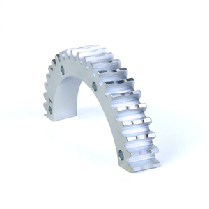
Professional CNC precision machining services for custom parts
Custom Machining Process
- Requirement Communication: Detailed understanding of customer needs, determining functionality, operating environment, stress conditions, etc.
- Design and Engineering: 3D modeling and engineering drawing creation,Mark dimensions, tolerances and technical requirements.
- Process Planning: Developing machining routes, selecting appropriate equipment and tools
- Programming and Machining: Writing CNC programs and performing precision machining
- Quality Inspection: Strict dimensional accuracy and surface quality testing
- Delivery and Support: Packaging and delivery of qualified products
Service Advantages
High Precision Guarantee
±0.01mm machining accuracy
Fast Delivery
7-15 working days delivery
Material Diversity
Supports various metal materials
Full Tracking
Real-time processing progress updates
Need Custom Machining Services?
Upload your CAD files and we will provide professional machining solutions and quotations
Technical Parameters Reference
Common Machining Parameters
- Spindle Speed: 1000-10000 rpm
- Feed Rate: 50-5000 mm/min
- Cutting Depth: 0.1-5 mm
- Machining Accuracy: ±0.01 mm
- Surface Roughness: Ra 0.4-1.6 μm
Material Machinability
- Aluminum Alloys: Easy to machine, high-speed cutting
- Stainless Steels: Difficult to machine, low-speed cutting
- Titanium Alloys: Difficult to machine, requires special processes
- Copper Alloys: Easy to machine,Attention chip evacuation
Zhang Ming
Precision Mechanical Engineer | 15 Years of Experience
Specialized in CNC machining technology research and application, expert in complex part processing optimization