
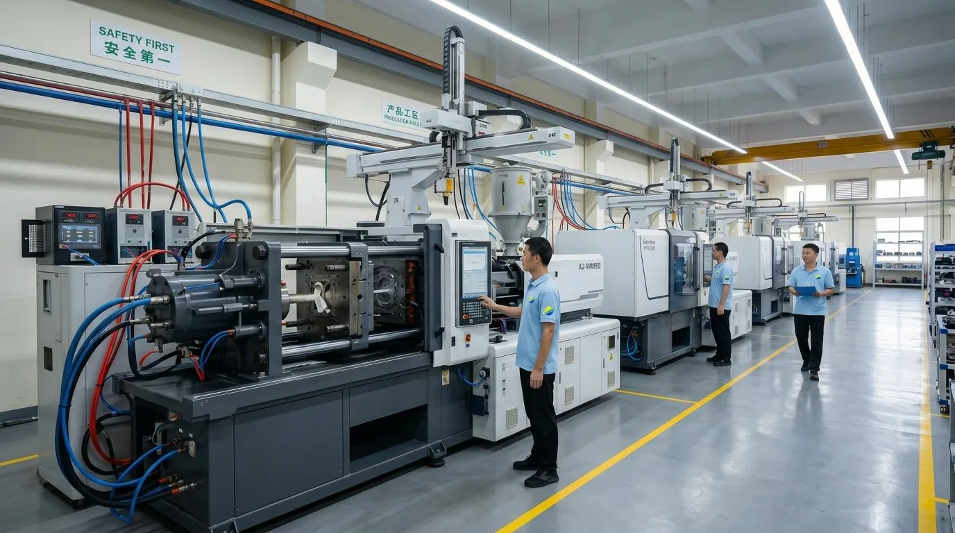
When Should You Choose Injection Molding?
Not every project benefits from this process. Understanding where injection molding excels — and where it does not — helps you make informed sourcing decisions early.
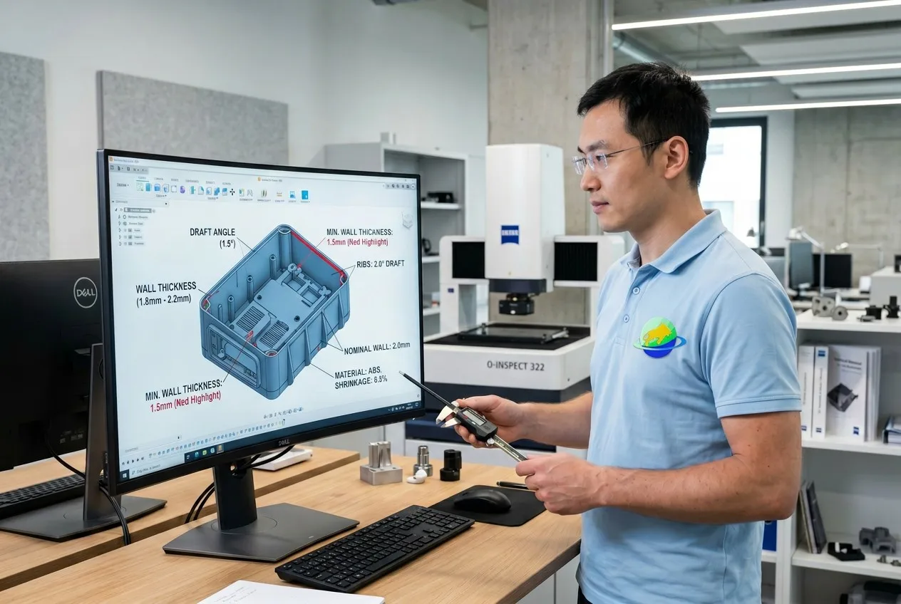
✓ Best suited when:
- Annual demand exceeds 1,000 pcs
- Part geometry requires complex features (bosses, ribs, snap-fits)
- Repeatability and tolerance consistency are critical
- Engineering plastics (PC, PA66, PEEK) are specified
- Surface finish quality must meet SPI/VDI standards
- Long production runs justify initial tooling investment
✗ Less suitable when:
- Only one prototype is needed — consider CNC or 3D printing
- Design changes frequently during development
- Total quantity is under 500 pcs
- Part size exceeds 800 mm — consider structural foam or compression molding
- Material requires extreme high-temperature resistance beyond PEEK range
Process Comparison at a Glance
| Criteria | Injection Molding | CNC Machining | 3D Printing |
|---|---|---|---|
| Volume > 1K | ✓ Ideal | Possible | ✗ |
| Complex geometry | ✓ | Limited | ✓ |
| Tolerance ±0.05 mm | ✓ | ✓ | ✗ |
| Unit cost at scale | Very low | Moderate | High |
| Lead time (tooling) | 3–6 weeks | 3–7 days | 1–3 days |
Injection Molding Process Step by Step
From initial concept to packaged delivery — each stage carries decisions that directly affect mold cost, cycle time, and final part quality.
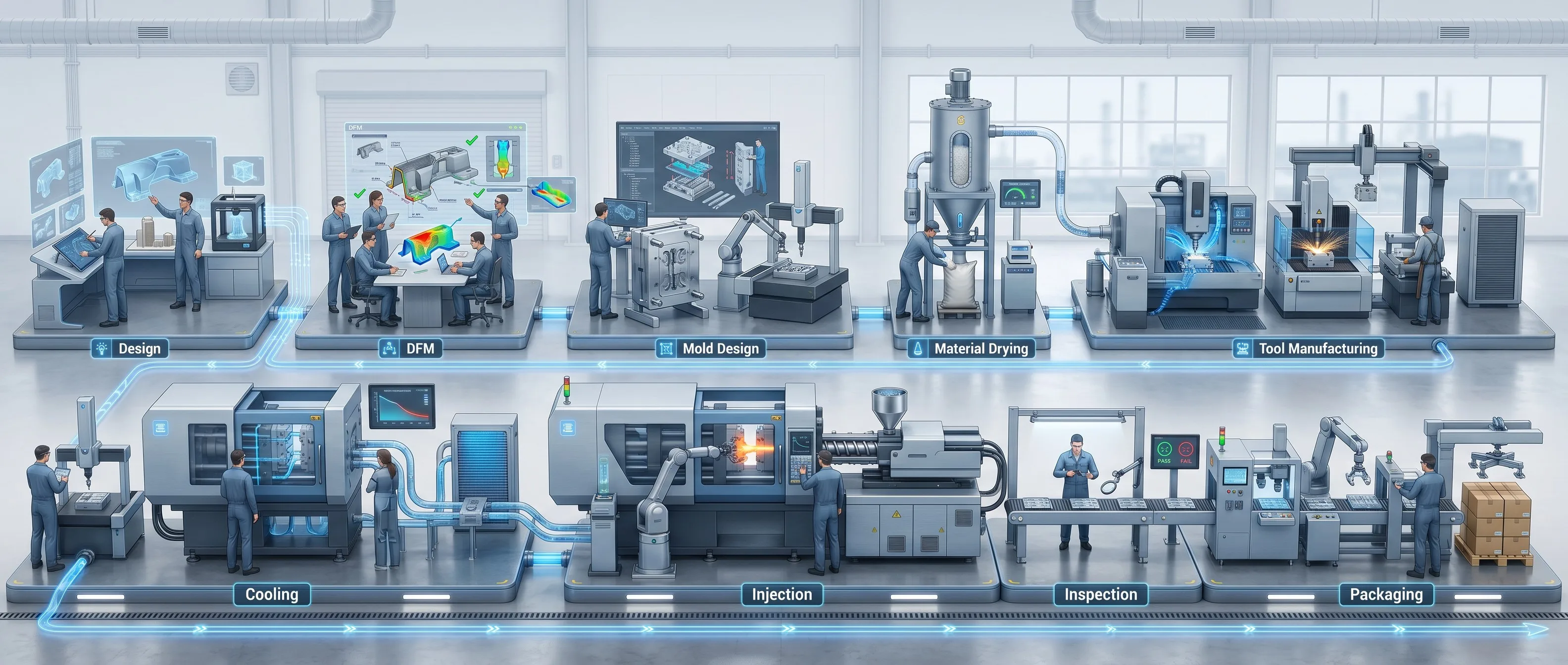
STEP 1
Part Design
Define wall thickness, draft angles, rib placement, boss geometry, and undercut features. These parameters directly influence mold complexity and production cost.
Key decisions: Uniform wall thickness (1.5–3 mm typical), minimum 1° draft per side, rib height ≤ 60% of wall thickness.
STEP 2
DFM Review
Before committing to tooling, a DFM (Design for Manufacturability) analysis identifies features that increase mold cost or risk defects — thin walls, sharp corners, impossible undercuts.
Why it matters: A single DFM correction can save \$2,000–\$10,000 in tooling rework.
STEP 3
Mold Design
Mold steel selection depends on production volume and part requirements. Core/cavity layout, gate type, cooling channel routing, and ejector pin positions are defined at this stage.
Steel grades: P20 (low volume, <300K shots), 718H (medium, 500K), H13 (high-temp alloys, 1M+), S136 (mirror polish, medical/optical).
STEP 4
Tool Manufacturing
The mold is CNC-machined from selected steel, then polished, assembled, and fitted with cores, cavities, ejector pins, and cooling circuits. Precision EDM and wire-cut operations create complex cavity details.
Key outputs: T0 mold trial confirms dimensional accuracy before T1 production sampling. Typical tooling lead time: 3–6 weeks.
STEP 5
Material Drying
Resin pellets are dried to eliminate moisture — critical for hygroscopic materials like PC, PA66, and PEEK. Improper drying causes silver streaks, splay marks, and reduced mechanical strength.
Drying parameters: ABS 80°C/2h, PC 120°C/4h, PA66 80°C/6h, PEEK 150°C/4h.
STEP 6
Injection Molding
Molten polymer is injected at high pressure (typically 800–1,500 bar) through the gate into the cavity. Packing pressure holds material in place as it begins to cool, compensating for shrinkage.
Parameters: Injection speed affects weld lines and air traps; packing pressure controls dimensional stability and sink marks.
STEP 7
Cooling
Cooling channels circulate water through the mold. Uniform cooling minimizes warpage and residual stress. Cooling time dominates cycle time — often 60–70% of total.
Optimization: Conformal cooling channels can cut cycle time by 15–30%. Uneven cooling causes warpage and dimensional variation.
STEP 8
Ejection
Once the part has solidified sufficiently, ejector pins push it free from the cavity. Draft angles ensure clean release without scoring or deformation.
Buyer note: Insufficient draft causes ejection marks and part sticking — a DFM-corrected draft angle prevents this entirely.
STEP 9
Inspection
First Article Inspection validates dimensions against drawing specs. In-process sampling ensures consistency across the run. Surface finishes range from SPI A-1 (mirror) to VDI 45 (textured matte).
Inspection tools: CMM, optical comparator, calipers, go/no-go gauges, surface roughness tester.
STEP 10
Packaging
Parts are packaged per customer requirements — individual bagging, tray packing, or bulk carton. Gate trimming, degating, and secondary operations (drilling, ultrasonic welding) are completed before packing.
Options: Custom labeling, barcoded packaging, VCI corrosion protection for metal-insert parts, and FSC-certified cartons available.
Materials for Injection Molding
Selecting the right resin is one of the earliest and most consequential decisions in any molding project. The table below covers the most commonly specified grades — and what each brings to your application.
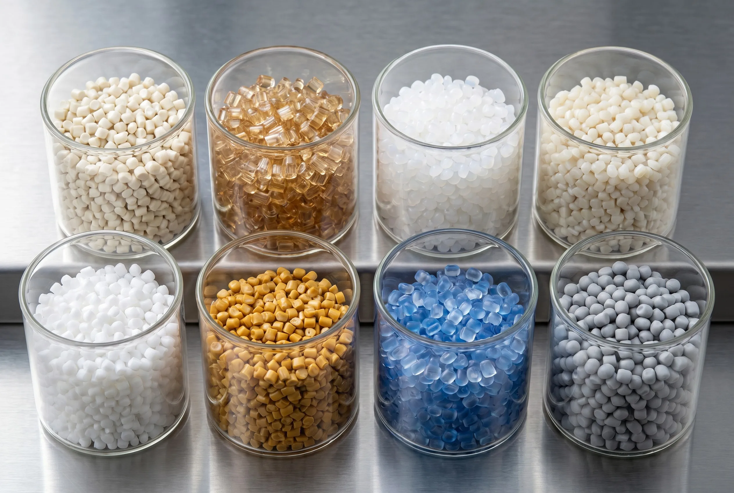
| Material | Key Properties | Typical Applications | Mold Temp (°C) |
|---|---|---|---|
| ABS | Good impact resistance, easy processing, cost-effective | Consumer electronics housing, automotive interior trim, toys | 50–80 |
| PC | High impact strength, transparency, heat resistance (130°C) | Medical device covers, LED lenses, safety equipment housings | 80–120 |
| PP | Low cost, chemical resistance, living hinge capability | Food containers, packaging caps, automotive battery cases | 20–60 |
| PA66 (Nylon) | High mechanical strength, wear resistance, good fatigue | Gear wheels, automotive structural brackets, cable connectors | 80–100 |
| POM | Excellent dimensional stability, low friction, high stiffness | Precision gears, valve bodies, conveyor rollers, fasteners | 80–100 |
| PEEK | Extreme heat resistance (260°C), chemical inertness, aerospace-grade | Aerospace bushings, surgical instrument handles, semiconductor tools | 160–200 |
| TPU | Flexible, abrasion-resistant, good elongation | Phone cases, medical tubing, overmolded grips, cable jackets | 20–40 |
| TPE | Soft touch, recyclable, overmolding compatible | Sealing gaskets, soft-grip tool handles, consumer product buttons | 20–40 |
Note on UL94 V0: For applications requiring flame retardancy — emergency stop buttons, electrical enclosures, aviation interior parts — flame-rated ABS (UL94 V0) and PC/ABS blends are available. Goldcattle verifies compliance through third-party lab testing before production.
Design for Manufacturability (DFM)
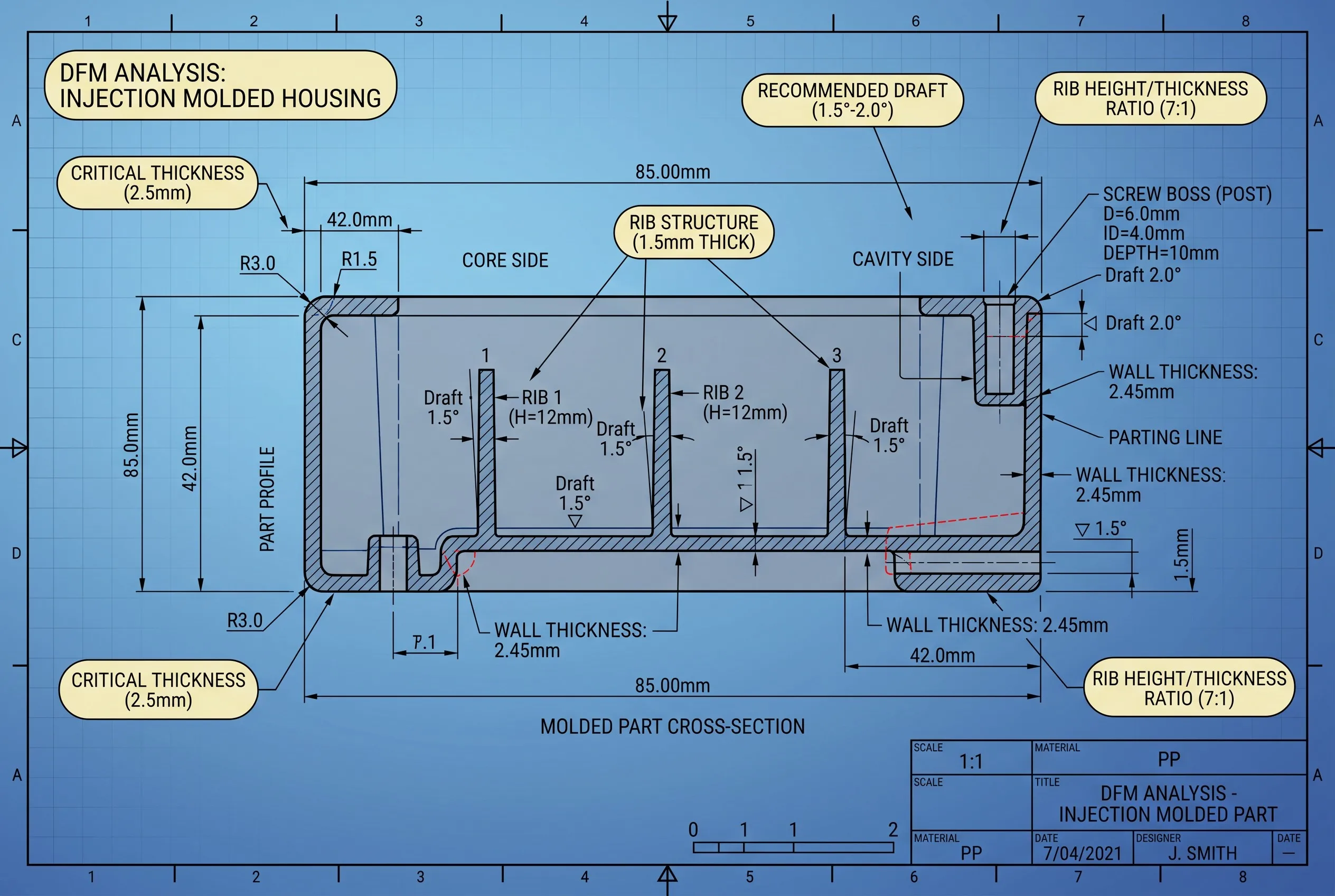
The decisions made in CAD directly determine mold cost, cycle time, and defect risk. Below are the eight design parameters that matter most — and what happens when they are ignored.
Wall Thickness
Keep uniform 1.5–3 mm. Variations >15% cause sink marks and internal stress.
Draft Angle
Minimum 1° per side (2° for textured surfaces). Zero draft = stuck parts and mold damage.
Corner Radius
Sharp corners concentrate stress. Use R ≥ 0.5 mm everywhere — R/wall = 0.5 is ideal.
Boss & Rib Design
Rib height ≤ 60% of wall. Boss wall = 0.6× nominal. Core out thick bosses to prevent sinks.
Snap Fit
Undercut depth ≤ wall thickness. Use radiused root to avoid fracture during assembly.
Living Hinge
PP only. Hinge thickness 0.25–0.5 mm, width 2–5 mm. Tested for 1M+ flex cycles.
Gate Location
Gate placement affects weld lines, flow length, and appearance. Edge/submarine/diaphragm — choose per part geometry.
Undercut Handling
Side cores or lifters add \$1K–\$5K per undercut. Minimize count early in design.
Common Injection Molding Defects and Solutions
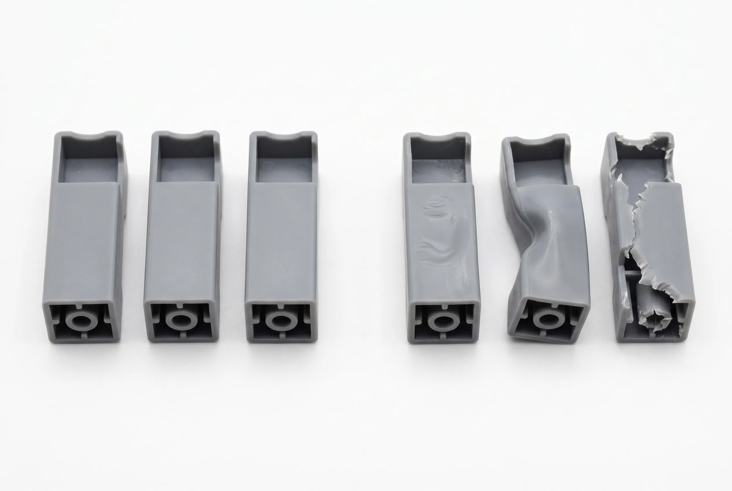
Even well-designed parts can exhibit defects when process parameters are off. Recognizing root causes early prevents costly rework and production delays.
| Defect | Root Cause | Solution |
|---|---|---|
| Sink Marks | Thick sections cool slower, causing surface depressions near bosses or ribs | Reduce rib/boss thickness; increase packing pressure and time; core out thick bosses |
| Warping | Non-uniform cooling or inconsistent wall thickness creates internal stress | Equalize wall thickness; optimize cooling channel layout; reduce injection speed for thin-wall parts |
| Short Shot | Insufficient material volume or blocked flow path fills cavity partially | Increase injection pressure; widen gate; verify resin drying; check for vent blockage |
| Flash | Excess pressure forces material between mold halves at the parting line | Reduce packing pressure; verify mold clamp force; clean parting line surfaces; adjust shot size |
| Burn Marks | Trapped air overheats, causing localized discoloration or degradation | Add or enlarge vents; reduce injection speed; check vent placement at flow end |
| Air Traps | Air enclosed by converging flow fronts cannot escape through vents | Relocate gate to change fill pattern; add vents at last-fill locations; adjust flow velocity |
| Silver Streaks | Moisture in resin vaporizes at injection temperature, leaving streaks | Dry resin thoroughly per spec (especially PC, PA66); verify hopper dryer operation; use dehumidifying dryer |
| Weld Lines | Two flow fronts meet, forming a visible seam with reduced strength | Move gate to shift weld line to non-critical area; increase melt temperature; add overflow well |
Our Injection Molding Capabilities
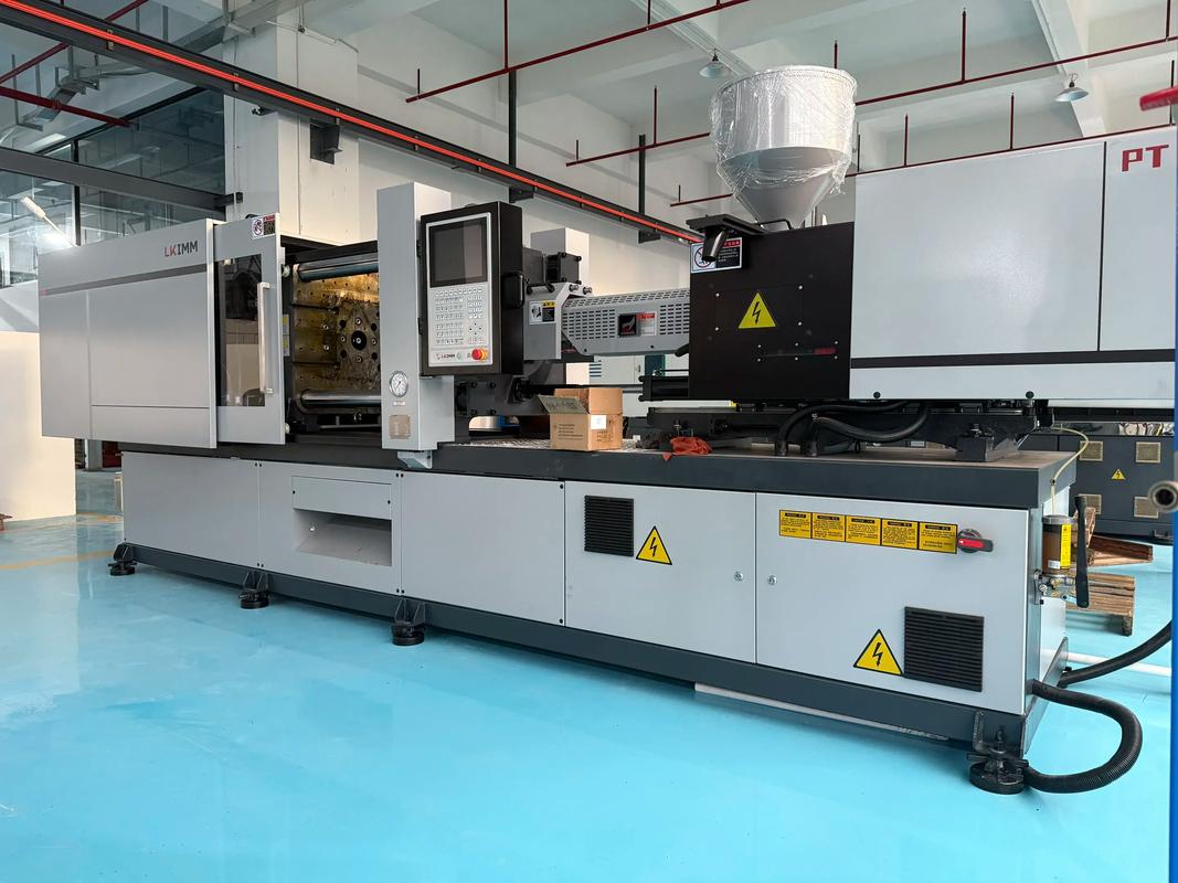
Xiamen Goldcattle operates 26 injection molding machines ranging from 80 to 1,200 tons, supporting everything from micro-optical lens housings to large industrial enclosures — all under ISO 9001:2015 certified processes.
Machine Range
80 – 1,200 T
26 machines in operation
Mold Life
300K – 1M+
Depending on steel grade selected
Tolerance
±0.05 mm
Verified by CMM inspection
Max Part Size
600 × 400 mm
1,200T machine class
Materials
50+ Resins
Including PEEK, UL94 V0 grades
Surface Finish
SPI A-1 / VDI
Mirror polish to textured matte
Goldcattle’s custom injection molding workflow covers mold design → DFM analysis → tool fabrication → T1 sampling → production run → QC inspection → global shipping. Every project receives a dedicated project engineer who coordinates design review, material qualification, and milestone tracking from first article through final delivery.
Industry Applications
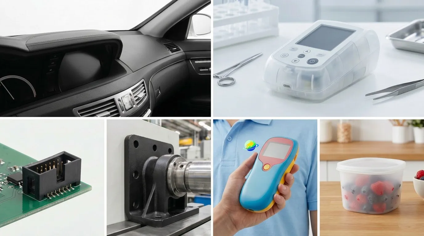
Injection molding serves virtually every manufacturing sector. Below are the industries where Goldcattle delivers the most value — with materials, tolerances, and compliance standards matched to each domain.
Automotive
Sensor housings, interior trim, connector blocks, structural brackets. Materials: PA66-GF30, POM, ABS/PC blend. Compliance: IATF 16949 traceability.
Medical Devices
Diagnostic covers, surgical handles, fluidic manifolds, sterile enclosures. Materials: PC, PEEK, medical-grade PP. Surface: SPI A-2 or A-1. ISO 13485 capable.
Industrial Equipment
Valve bodies, conveyor components, gear assemblies, heavy-duty brackets. Materials: PA66, POM, reinforced PP. High-wear and chemical-resistance applications.
Electronics & Electrical
Connector housings, PCB enclosures, switch bodies, EMI-shielded cases. Materials: UL94 V0 ABS, PC, PBT. Flame retardancy certification available.
Consumer Products
Appliance housings, ergonomic grips, packaging closures, outdoor gear. Materials: ABS, TPU overmold, PP. Surface finishes from high-gloss to soft-touch.
Food & Packaging
Containers, caps, dispensers, food-contact safe parts. Materials: FDA-compliant PP, PE, PET. Cleanroom molding available for sensitive applications.
Case Studies
Real projects demonstrate what optimized design, proper material selection, and controlled processing achieve in practice.
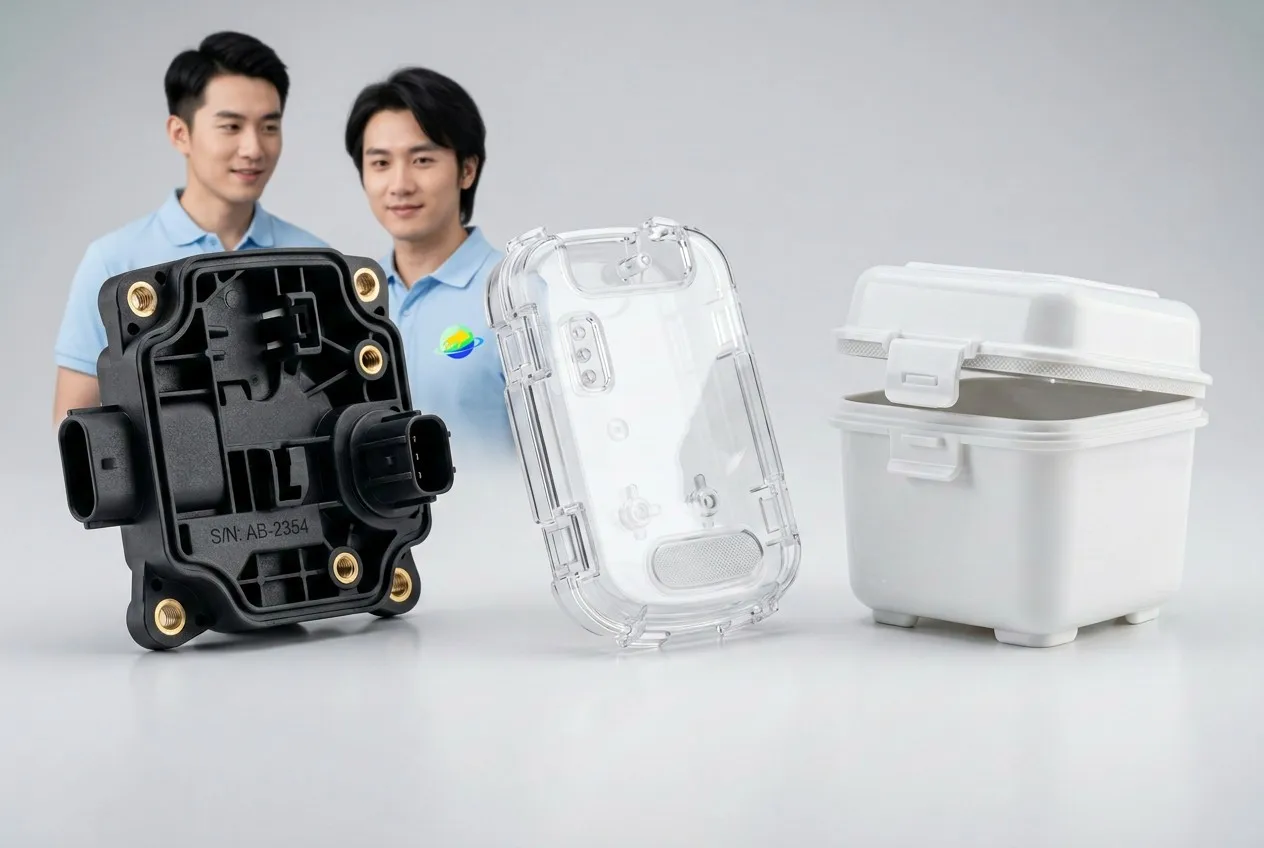
CASE 01
ABS Automotive Sensor Housing
| Industry | Automotive |
| Material | ABS + PA66-GF30 insert |
| Quantity | 20,000 pcs / batch |
| Tolerance | ±0.08 mm |
| Surface | SPI B-2 semi-gloss |
DFM review eliminated 3 undercuts, reducing mold cost by \$4,500. Insert molding achieved metal-to-plastic bond without secondary assembly.
CASE 02
PC Medical Diagnostic Cover
| Industry | Medical Devices |
| Material | Medical-grade PC |
| Quantity | 50,000 pcs annual |
| Tolerance | ±0.05 mm (CMM) |
| Surface | SPI A-2 mirror polish |
S136 stainless mold for optical clarity. Snap-fit design validated through 10K cycle testing. Cleanroom packaging for sterile delivery.
CASE 03
PP Food-Grade Container with Living Hinge
| Industry | Food & Packaging |
| Material | FDA-compliant PP |
| Quantity | 100,000 pcs / month |
| Tolerance | ±0.15 mm |
| Feature | Integrated living hinge |
Living hinge tested to 1M+ flex cycles. Single-cavity mold with hot runner system minimized gate vestige and material waste. Cycle time: 8 seconds.
Quality Control Process
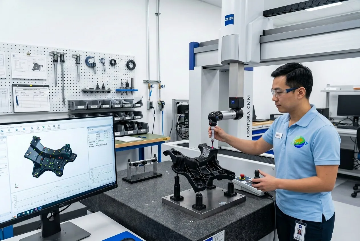
Consistent quality is not an outcome of luck — it is a structured process. Goldcattle applies six inspection checkpoints across every production run, ensuring that each shipment meets drawing specifications.
1. Incoming Material
Resin lot verification, moisture testing, MFI measurement, color matching against standard.
2. First Article Inspection
Full dimensional layout against drawing. CMM report, surface finish, visual defect check.
3. In-Process Sampling
Statistical sampling every 2 hours. Weight, dimension, appearance against control limits.
4. CMM Dimensional
Zeiss CMM validates critical features: tolerances, GD&T, hole positions, flatness, concentricity.
5. Final Inspection
100% visual for cosmetic parts; AQL sampling for structural parts. Packaging integrity check.
6. Packaging & Shipping
Custom packaging per spec — individual bags, foam trays, or bulk cartons. Fumigation for wood crates.
Why Work with Xiamen Goldcattle?
With 26 years of precision manufacturing experience, Goldcattle combines engineering depth with production scale — delivering custom injection molded parts that meet international quality standards at competitive cost.
Full-Service Custom Manufacturing
- DFM analysis before every tooling commitment
- Mold design and fabrication (P20 through S136 steel grades)
- T1 sample review with dimensional CMM report
- Production runs from 1,000 to 1M+ parts
- Global shipping to 40+ countries
Engineering Capabilities
- 26 injection machines (80–1,200T) for multi-size coverage
- 50+ resin types including UL94 V0 and medical-grade
- Overmolding and insert molding for multi-material parts
- ISO 9001:2015 certified; ISO 13485 capable for medical
- NDA protection and export mold ownership
Goldcattle’s streamlined workflow: Send your STEP/CAD/drawing → Receive DFM report + quotation within 24 hours → Approve tooling → T1 samples in 3 weeks → Production and delivery on schedule.
Frequently Asked Questions
The questions below reflect what B2B buyers ask most often when evaluating injection molding suppliers — covering cost, lead time, materials, and service terms.
How long does injection molding take from design to delivery?
Tooling typically requires 3–6 weeks depending on mold complexity (side cores, lifters, hot runners add time). Once T1 samples are approved, production runs of 5,000–50,000 pcs ship in 1–3 weeks. Micro-molds for simple geometries can be completed in 2 weeks.
How much does an injection mold cost?
Mold cost depends on part size, complexity (undercuts, side cores), surface finish requirement, and steel grade. Simple single-cavity molds start around \$1,500–\$3,000. Multi-cavity production molds with hot runners range from \$8,000–\$30,000+. Goldcattle provides detailed cost breakdowns in every quotation.
What is the minimum order quantity for injection molding?
Practical MOQ depends on part size and mold cavitation. For most projects, 1,000–3,000 pcs is the minimum that justifies tooling investment. Goldcattle supports pilot runs of 100–500 pcs using single-cavity test molds for validation before committing to production tooling.
Can you help optimize my part design for molding?
Yes. Goldcattle provides free DFM analysis with every quotation — identifying wall thickness issues, undercut cost drivers, gate placement, and potential defect risks. In most cases, 2–3 design adjustments reduce tooling cost by 20–40% and improve production yield.
How long does tooling take?
Standard single-cavity molds: 3–4 weeks. Multi-cavity molds with side cores: 5–6 weeks. Hot runner molds: 6–8 weeks. Goldcattle tracks milestones weekly and shares progress photos at CNC machining, polishing, and T1 trial stages.
Can you provide prototypes before committing to tooling?
Yes. Goldcattle offers CNC-machined plastic prototypes and 3D-printed samples for design validation before mold investment. These protoypes help verify fit, function, and aesthetics — but surface finish and tolerances differ from molded production parts.
Do you sign NDA agreements?
Absolutely. Standard NDA templates are available, or we can review your company’s agreement. All files, drawings, and design data are stored on encrypted servers with access restricted to assigned project engineers only.
Can I export the mold after production?
Yes. Goldcattle supports full mold export — the mold belongs to you. We coordinate logistics, documentation, and customs clearance for mold shipment to your facility or designated storage location worldwide.
Can you support low-volume production?
For volumes under 3,000 pcs where full production tooling is not cost-effective, Goldcattle offers bridge tooling (aluminum molds, 10K–50K shot life) and CNC machining as alternatives. We match the process to your volume and budget reality.
What materials can be injection molded?
Over 50 engineering resins are moldable. The most commonly specified include ABS (consumer housings), PC (transparent/impact), PP (low-cost/living hinges), PA66/Nylon (structural/wear), POM (precision/low friction), PEEK (aerospace/medical at 260°C), TPU (flexible/overmold), and TPE (soft-touch/gaskets). Flame-rated UL94 V0 grades, glass-fiber-reinforced blends, and medical-grade ISO 13485 materials are also available. Goldcattle stocks 30+ resins and can source specialty grades on request.
Need Custom Injection Molded Parts?
Send us your design files and receive a complete project evaluation — DFM report, quotation, and mold cost estimate — within 24 hours.
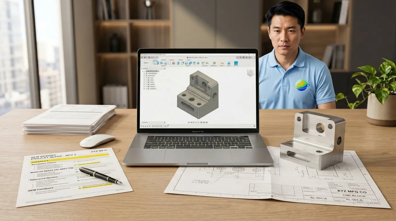
Upload Your Files
STEP / CAD / 2D Drawing / Physical Sample / Reference Photo
Receive Within 24 Hours
DFM Report / Itemized Quotation / Mold Cost Estimate / Lead Time Schedule
NDA protection guaranteed. ISO 9001:2015 certified facility. Shipping to 40+ countries.
3D Printing vs. Injection Molding: When to Switch
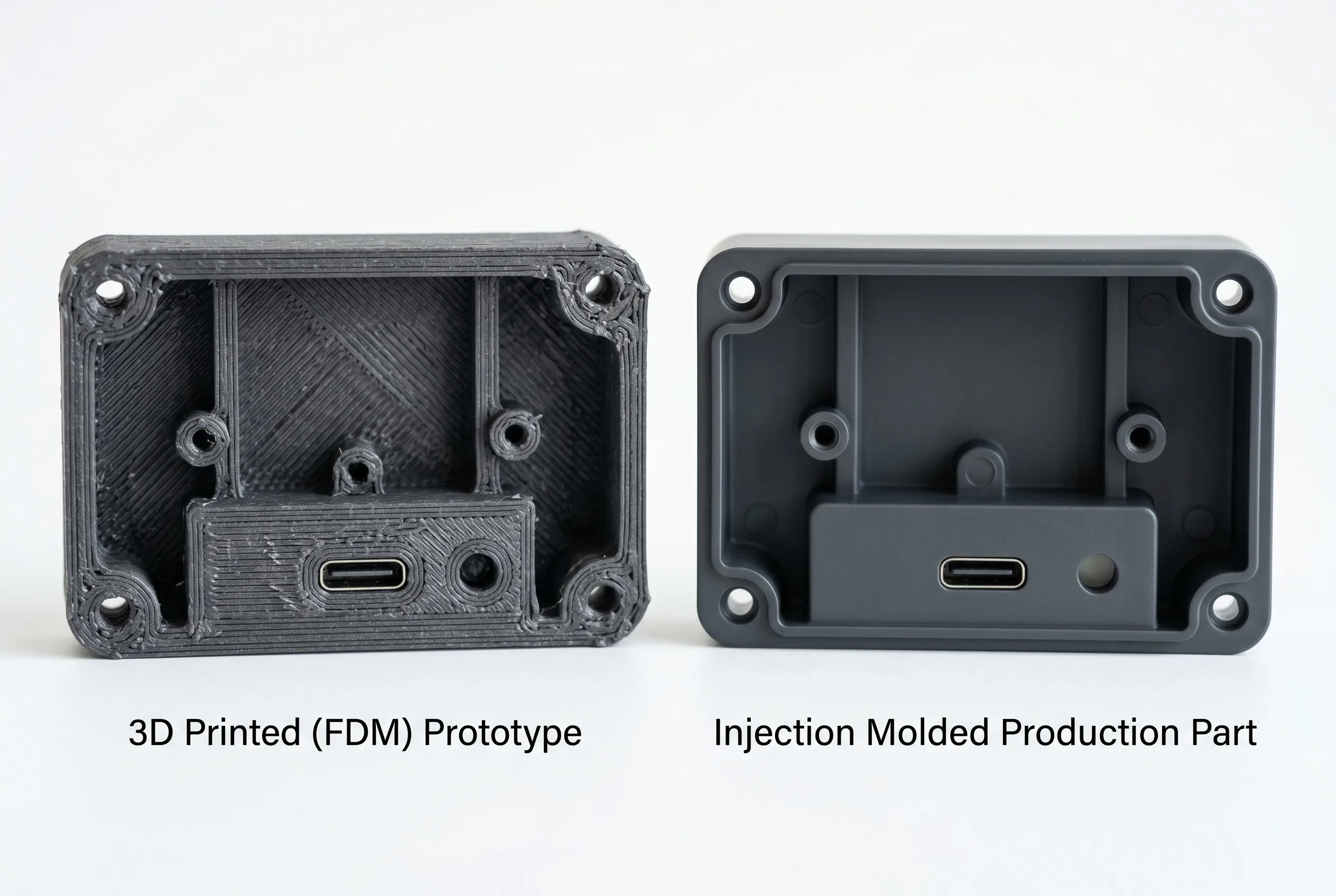
Many product teams prototype with 3D printing, then struggle to decide when to transition to production molding. The comparison below clarifies that decision point.
| Factor | 3D Printing (FDM/SLA) | Injection Molding |
|---|---|---|
| Best volume range | 1 – 100 pcs | 1,000 – 1M+ pcs |
| Surface quality | Visible layer lines, rough | SPI A-1 mirror to textured matte |
| Dimensional accuracy | ±0.2–0.5 mm | ±0.05 mm (CMM verified) |
| Material options | Limited (PLA, ABS-like resin) | 50+ engineering resins |
| Per-part cost at 10K | \$15–\$80 each | \$0.50–\$3 each |
| Lead time (first parts) | 1–3 days | 3–6 weeks (tooling) |
| Structural integrity | Anisotropic (weak along Z) | Isotropic (consistent strength) |
Decision rule: If your annual forecast exceeds 1,000 pcs and the design is stable (no more than 2–3 revisions expected), the total cost of tooling amortized over production volume will be lower than cumulative 3D printing costs by approximately the 500-piece mark. Goldcattle can bridge this transition — providing CNC or 3D printed prototypes for validation, then seamlessly switching to production tooling once you approve.
Recommended Reading
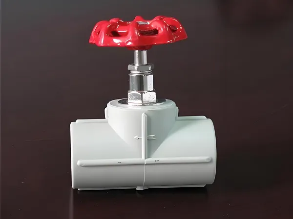
Customized PVC Globe Valves
PVC (polyvinyl chloride) globe valve is a kind of fluid control equipment widely used in chemical industry, water treatment, agricultural irrigation and other fields. It is made of PVC material,…
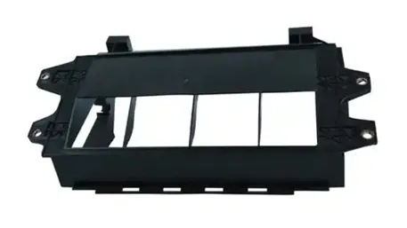
Rapid Prototyping Plastic Injection Molding Parts
1. Technical Overview of Rapid Prototyping in Injection Molding Rapid prototyping for plastic injection molding enables accelerated product development by producing functional prototypes in 5–15 days, bridging the gap between design validation and…
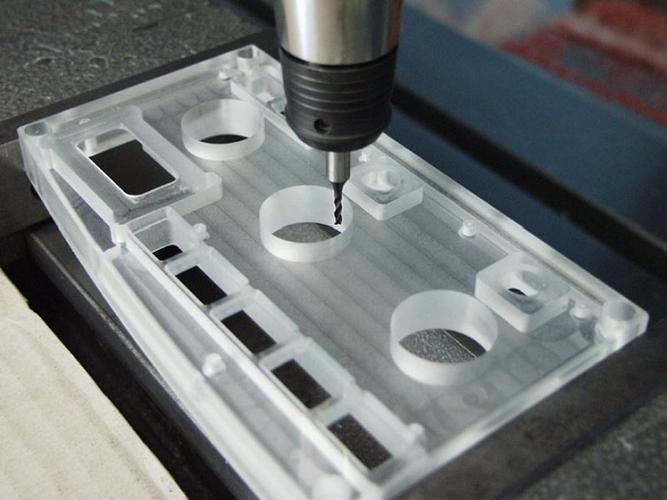
CNC Plastic Machining Prototypes
CNC Plastic Machining Prototypes – Fast, High-Precision Custom Parts We provide CNC plastic machining prototype services for fast, accurate, and functional parts to support your product development process, covering EVT,…
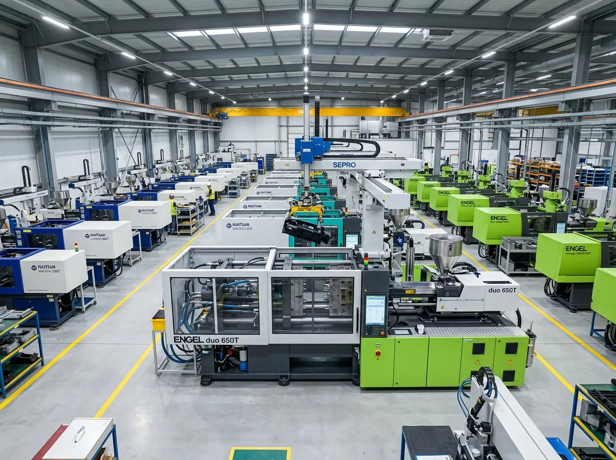
custom processing furniture abs shell cover plastic injection mould
Custom ABS Plastic Shell Cover Manufacturer OEM Injection Molding for Furniture, Electronics and Industrial Equipment ✓ Mold Design ✓ DFM Analysis ✓ Injection Molding ✓ Surface Texture ✓ Assembly ✓…
What is the lifespan of an injection mold?
Answer The lifespan of injection – molding molds varies greatly and there is no fixed value. Simple molds with low requirements may only be used for tens of thousands of…
What is CNC form milling?
Answer CNC profile milling refers to a machining process where a numerically controlled (CNC) system guides a profile milling cutter to machine specific cross-sectional contours or 3D cavities directly, by…