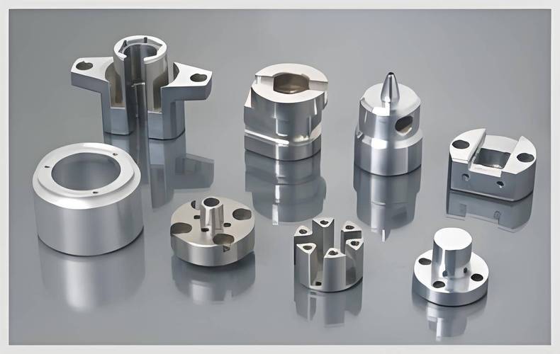
What Are Precision Mold Parts?
Precision mold parts are high-tolerance tooling components used to manufacture parts or products with high precision, complex shapes, and fine details. These include cores, cavities, inserts, sliders, lifters, guide pins and bushings, and ejector pins. Unlike generic mold components, precision mold parts are machined to exacting tolerances — typically ±0.005 mm or better — and directly determine cavity consistency, sealing integrity, mold life, and part quality across every cycle.
In summary, precision mold parts are high-accuracy tooling components machined to micron-level tolerances that determine the dimensional consistency and service life of an injection mold across every production cycle.
Why Precision Mold Components Matter in Injection Molding
In injection molding, the quality of the final plastic part is determined at the tooling level. The core, cavity, and insert tolerances control whether a mold produces 100,000 identical parts or begins drifting out of spec after the first 5,000 shots. Because the mold cavity depth directly controls wall thickness, even minor deviations in core dimensions can lead to inconsistent fill rates, warped parts, or parts that fail dimensional inspection.
The cost of under-specifying precision mold parts isn‘t captured in the mold purchase price — it shows up later:
- If cavity and core inserts have insufficient hardness (<48 HRC), wear accelerates, and dimensions begin drifting after as few as 10,000–30,000 cycles — triggering in-spec parts early in the run and rejected parts later.
- If guide components (pins, bushings) have loose tolerances (>0.01 mm positional), the mold halves misalign, causing flash, premature shut-off surface wear, and part non-conformance.
- If ejector pins are not precision-ground to diameter tolerance ±0.005 mm, they can bind, gall, and cause unscheduled mold downtime — each hour of which costs the molder both machine time and labor.
According to SPI standards, Class 101 molds require cavity and core surfaces to be hardened to 48–52 HRC, with an expected mold life of over 1 million cycles. If hardness or component interchangeability is downgraded to Class 103 (28 HRC), mold life expectancy drops below 500,000 cycles, and maintenance downtime frequency and cost increase significantly.
In summary, precision mold parts are not a cost-up item — they are the engineering control that determines whether a mold delivers consistent part quality across its designed service life. Under-specifying these components transfers risk from the mold purchase price to future production losses.
Our Precision Mold Parts Manufacturing Capabilities
Tolerances We Hold
| Tolerance Level | Range | Typical Application | Cost Driver |
|---|---|---|---|
| Standard (ISO 2768-m) | ±0.1 mm | Non-critical structural features | Baseline cost |
| Precision CNC Machining | ±0.01 mm | General mold components, guide elements | Moderate cost |
| Jig Grinding High Precision | ±0.005 mm | Critical core/cavity dimensions, shut-off surfaces | Requires specialized equipment |
| Wire EDM / Mirror EDM | ±0.002 mm | Micro features, tight corners, connector molds | Highest precision processes |
Standard tolerances of ±0.1 mm are adequate for most non-critical features; precision tolerances of ±0.005 mm require specialized equipment including jig grinding and wire EDM. High-precision tolerances of ±0.002 mm are achievable for micro features and tight corners using wire EDM and mirror EDM processes.
Surface Finish Capability
| Finish Type | Ra Value Range | Application |
|---|---|---|
| As-Machined (CNC) | Ra 0.8–3.2 μm | Non-cosmetic surfaces |
| Fine Ground | Ra 0.2–0.4 μm | Shut-off surfaces, guide components |
| Mirror Polished | Ra ≤0.05 μm | Optical-grade mold cavities |
Precision mold parts require surface finishes ranging from Ra 0.2 μm for functional surfaces to Ra ≤0.05 μm for optical-grade mirror finishes.
Materials & Heat Treatment
| Material | Standard / Grade | Typical Hardness | Application |
|---|---|---|---|
| H13 Hot Work Tool Steel | 4Cr5MoSiV1 / 1.2344 / SKD61 | 48–52 HRC (vacuum heat treated) | Cores, cavities, slides, lifters — aluminum/zinc casting and injection molding |
| S136 / 420SS Stainless Steel | DIN 1.2083 / AISI 420 | 48–52 HRC | High-polish mirror-finish cavities; corrosion-resistant applications |
| P20 Pre-Hardened Steel | 3Cr2Mo / 1.2311 | 28–32 HRC (pre-hardened) | Mold bases, non-wear structural components |
| Carbide (Cemented Carbide) | Varies | 78–92 HRA | Extreme wear inserts for abrasive materials |
Material selection directly affects mold life, part quality, and corrosion resistance. H13 with vacuum heat treatment to 48–52 HRC delivers the optimal balance of high-temperature strength and thermal fatigue resistance for production molds. S136 stainless steel at equivalent hardness adds corrosion resistance for PVC or humid environments where standard tool steel would degrade.
Manufacturing Processes
| Process | Capability / Role | Key Equipment |
|---|---|---|
| CNC Milling (3-axis / 5-axis) | Precision contouring of cores, cavities, inserts, sliders | 5-axis CNC machining center |
| Wire EDM | Intricate internal features, tight corners, ejector pin holes | Slow wire EDM |
| Sinker EDM | Deep ribs, complex cavity details unreachable by cutting tools | Mirror spark EDM |
| Jig Grinding / Precision Grinding | Achieve ±0.005 mm tolerance on critical dimensions; achieve Ra 0.2–0.4 μm surface finish | CNC jig grinder, surface grinder |
| Vacuum Heat Treatment | Uniform hardness 48–52 HRC with minimum distortion | Vacuum heat treatment furnace |
From CNC contouring to wire EDM for intricate details and jig grinding for ±0.005 mm tolerances, our multi-process capability means we can manufacture complete precision mold components without outsourcing critical steps — reducing lead time risk and retaining full quality control throughout the manufacturing chain.
Technical Documentation We Provide
For engineers and procurement teams evaluating a precision mold parts supplier, the documentation provided with each order is not an add-on — it is the evidence that what was ordered is what was delivered, to specification, and can be verified independently. Technical documentation bridges the gap between the manufacturer’s claim and verifiable compliance.
| Documentation | What It Contains | Why It Matters to the Buyer |
|---|---|---|
| 2D Detailed Drawings | Dimensional drawings with GD&T callouts, tolerance stack-up analysis per ASME Y14.5 | Enables future maintenance and replacement without dependency on original supplier |
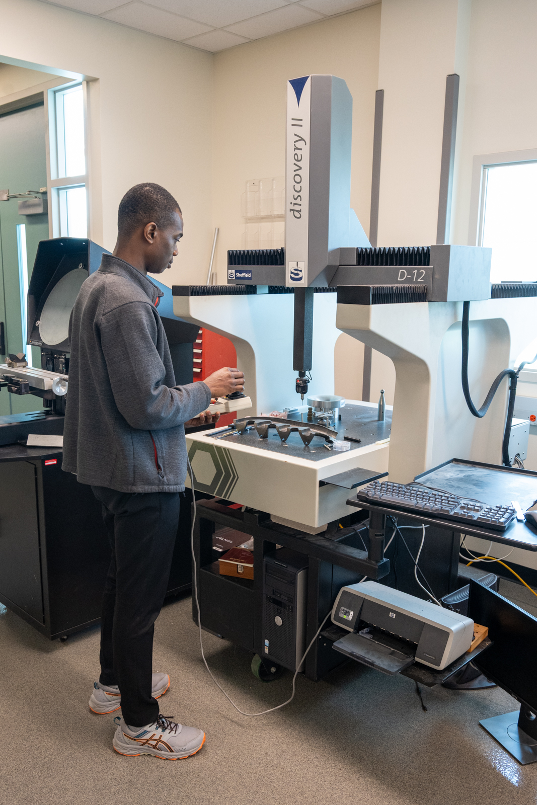
| CMM Inspection Report | Full dimensional verification report with measured values for all critical features | Provides independent verification that delivered parts conform to drawing; supports PPAP submission |
| Material Certificate (Mill Cert) | Certificate of material grade, chemical composition, heat number | Ensures traceability to material source; verifies that specified material was actually used |
| Heat Treatment Report | Heat treatment process parameters, achieved hardness values (HRC) | Verifies that heat treatment met specification; critical for mold life assurance |
| DFM Report | Engineering analysis of part manufacturability, identified risks, optimization suggestions | Demonstrates proactive engineering engagement before machining; reduces downstream rework cost |
| FAI Report | Comprehensive dimensional report on first-off sample per AS9102 | Verifies production capability before full run; required by aerospace, medical, automotive OEMs |
These documents form a traceable quality record from material to finished component — enabling our customers to verify compliance independently, support their own PPAP submissions, and maintain their molds over their entire production life without being locked into a single supplier for replacement components.
Mold Standards & Quality Compliance
For buyers specifying precision mold parts, adherence to recognized industry standards is a non-negotiable baseline — not a differentiator. The following standards form the framework against which our manufacturing quality is measured.
SPI Mold Classification Standards
The Society of the Plastics Industry (SPI) developed injection mold classification standards, covering 5 grades from Class 101 to Class 105, defining mold life, material requirements and manufacturing precision:
| SPI Class | Life Expectancy | Cavity/Core Hardness | Typical Application |
|---|---|---|---|
| Class 101 | >1,000,000 cycles | 48–52 HRC | Extremely high volume; long-life precision production |
| Class 102 | ≤1,000,000 cycles | 48–52 HRC | Medium-to-high volume; abrasive materials; tight tolerances |
| Class 103 | <500,000 cycles | ≥28 HRC (hardened if required) | Medium volume; non-abrasive materials |
| Class 104 | <100,000 cycles | ≥28 HRC | Low volume; prototype and bridge tooling |
ISO Standards
- ISO 2768: General tolerance standard for linear and angular dimensions, with f (fine), m (medium), c (coarse) grades. Our precision mold parts default to ISO 2768-f for unmarked tolerances.
- ISO 9001: Quality management system certification, ensuring full traceability of quality from material procurement to shipping inspection.
- ISO 286: Limits and fits system, covering IT6 tolerance grades. The main dimensional accuracy of molding components per SPI standards follows IT6 grade.
Where a part‘s drawing is otherwise silent on specific tolerances, we default to ISO 2768-f(precision grade). Where the drawing specifies GD&T callouts, we verify compliance via CMM measurement and deliver the inspection data with every shipment. Compliance with these standards ensures that mold components are manufactured consistently and can be independently verified by buyers.
Design Considerations for Precision Mold Parts
Beyond manufacturing precision, the design philosophy behind precision mold parts determines how well a mold performs over its entire service life — not just at mold trial.
Cavity and Core Design (Dimensional and Structural)
The cavity insert directly controls the outside surface and geometry of the molded part, while the core insert defines its internal features. For precision applications, cavity and core steels must be hardened to 48–52 HRC per SPI Class 101/102 requirements. Wall thickness must be adequate to resist injection pressure — typically 15,000 psi or more for engineering resins — without deflection. Undersized core thickness may reduce steel cost but can lead to dimensional drift after the first several thousand cycles.
Procurement implication: Specifying Class 103 hardness (≥28 HRC) vs. Class 101 (48–52 HRC) reduces tooling cost but can result in accelerated wear, particularly with abrasive or glass-filled materials. This trade-off must be evaluated against planned production volume.
Gate and Runner Design
Gate position and size determine how the molten material enters the cavity — directly affecting filling balance, weld line location, and part appearance. Precision mold parts must account for gate design from the cavity machining stage: gate location is machined into the cavity or core insert, and its dimensions must be held to tight tolerances to ensure consistent material flow shot-to-shot. Poor gate design leads to short shots, uneven shrinkage, and visible gate vestige that degrades product aesthetics.
Cooling System Design
The cooling circuit layout inside mold plates and inserts controls cycle time and part consistency. Conformal cooling channels — machined to follow the contour of the cavity — can reduce cycle time by 20-40% compared to straight-drilled lines for complex geometries. The machining precision of cooling channel diameter and position directly affects cooling uniformity: uneven cooling causes differential shrinkage and warpage.
Procurement implication: Cooling system design is not just an engineering detail — it directly determines your per-part cost. A 20% reduction in cycle time means 20% more parts per shift, making well-designed cooling channels one of the fastest-return investments in mold manufacturing.
Interchangeability and Maintenance Design
For production molds that will operate for hundreds of thousands of cycles, individual precision components (guide pins, bushings, ejector pins, inserts) will inevitably wear. Sub-inserts can extend overall tool life by 30–50% by isolating wear to replaceable components, protecting the main mold structure, and enabling targeted replacement of worn sections rather than entire cavity or core blocks. The specification that each precision component in a mold must be interchangeable with a replacement part — without hand-fitting or re-machining — is what distinguishes production-grade tooling from prototype-grade tooling.
Procurement implication: Molds designed without replaceable inserts shift maintenance cost from component replacement to cavity/core re-machining or entire mold replacement. The incremental upfront cost of insert-based design is typically recovered in the first major maintenance event.
In summary, precision mold parts design must account for four interdependent factors — structural integrity under injection pressure, balanced material flow through gate and runner geometry, uniform cooling to control cycle time and warpage, and interchangeability to minimize maintenance cost — all of which directly affect total cost of mold ownership, not just the initial tooling purchase price.
Common Mold Part Problems & Our Solutions
We systematically address common failure modes through material selection, precision machining, standardized hardening, and documented inspection, to eliminate production disruption risk.
| Problem | Root Cause | Commercial Impact | Our Solution |
|---|---|---|---|
| Flash / Burr on Parts | Worn shut-off surfaces; insufficient hardness on parting line inserts | Parts require secondary deflashing; mold downtime for repair; rejected batches | Hardened inserts (48–52 HRC) on all shut-off surfaces; precision grinding to flatness within 0.01 mm |
| Misalignment (Core/Cavity Shift) | Guide pin/bushing wear; loose fit tolerances after thermal cycling | Part wall thickness variation; flash; accelerated shut-off surface wear; part failure at assembly | Precision-ground guide components to H7/g6 fit; hardened guide bushings per SPI Class 101/102 |
| Short Tool Life | Insufficient heat treatment; wrong material selection for application | Unexpected mold repair cost; production interruptions; inconsistent part quality toward end of tool life | H13 vacuum heat treatment to 48–52 HRC per NADCA #207; material grade selection matched to resin abrasiveness |
| Dimensional Drift Across Batch | Gradual core/cavity wear; inconsistent process control; no in-line inspection | Parts that meet spec early in production fail later, causing field failures and warranty claims | In-process CMM inspection at defined intervals; documented tool wear tracking; scheduled insert replacement |
| Corrosion / Rust on Mold Surfaces | Inadequate material grade for humid or PVC processing environments; condensation during storage | Mold surface degradation; part surface defects; mold requires re-polishing or replacement | S136 / 420SS stainless steel for corrosive environments; proper mold storage with corrosion inhibitor |
| Ejector Pin Binding / Breakage | Pin-to-bore clearance too tight; insufficient pin hardness; thermal expansion mismatch | Production stoppage; damaged mold components; unscheduled maintenance | Precision-ground ejector pins with controlled clearance; hardened pin surfaces; proper ratio verification |
Case Study — High-Precision Cavity Insert for Medical Component
Project: Multi-Cavity Precision Insert Set for Medical Device Housing
Industry: Medical Device Manufacturing
Material: S136 Stainless Steel (48–52 HRC)
Challenge
The medical device housing required 8-cavity production with cavity-to-cavity consistency within ±0.02 mm on wall thickness and a mirror finish of Ra ≤0.05 μm on the functional sealing surfaces. Previous supplier was unable to maintain cavity-to-cavity consistency beyond 30,000 cycles, resulting in progressive wall thickness variation and 8% rejection rate in production.
Our Solution
- Selected S136 ESR-grade stainless steel for consistent metallurgical structure and polishability to Ra ≤0.05 μm mirror finish
- Applied vacuum heat treatment to achieve uniform 50 ±2 HRC across all cavity inserts, verified by hardness testing on every insert
- Performed wire EDM for cavity details below 1 mm radius, combined with jig grinding on shut-off surfaces to ±0.005 mm flatness
- Implemented CMM inspection with full dimensional report for all 8 cavities, measuring wall thickness at 12 defined points per cavity
Results
- Cavity-to-cavity consistency: ±0.012 mm (40% better than the ±0.02 mm requirement)
- Surface finish: Ra 0.04 μm mirror finish on sealing surfaces (within spec)
- Production performance: 200,000+ cycles with dimensional stability maintained; zero cavity replacement required
- Customer outcome: Medical device PPAP approved on first submission; subsequent repeat orders for additional cavity sets
This project demonstrates our approach to precision mold parts manufacturing — material selection matched to application, precision machining with verified inspection data, and documented quality records that support end-customer regulatory submissions. When a medical device customer requires PPAP-level documentation and micron-level precision, our engineering and quality systems deliver.
Why Choose Our Precision Mold Parts Manufacturing
Choosing a precision mold parts supplier requires evaluating more than unit price. The cost of inadequate precision — dimensional drift, unexpected mold downtime, rejected production batches — accrues over the mold‘s service life, not at the purchase order stage. Our manufacturing service is built to minimize that lifecycle cost:
- Precision Capability: Tolerances to ±0.005 mm; surface finishes to Ra ≤0.05 μm mirror polish
- Materials Compliance: H13, S136, P20, carbide — with full material traceability and mill certificates
- Standards Alignment: SPI Class 101–104 mold classifications; ISO 2768-f tolerance framework; ISO 9001 quality management
- Documentation Package: CMM reports, material certificates, heat treatment reports, DFM analysis — documentation package delivered with every order
- Lifecycle Support: Interchangeable insert design for maintenance efficiency; replacement component availability through documented 2D drawings
In summary, the right precision mold parts supplier delivers more than components — they provide verified precision, documented quality, material traceability, and lifecycle support that minimize total cost of mold ownership over the mold‘s entire production life.
FAQ — Precision Mold Parts
Q1: What are precision mold parts?
Precision mold parts are high-tolerance tooling components such as cores, cavities, inserts, sliders, lifters, guide pins and bushings, and ejector pins — machined to tolerances as tight as ±0.005 mm or better. They are used in injection molds, die casting dies, and other tooling to ensure cavity consistency, sealing integrity, and mold life across every production cycle.
Q2: What tolerances can precision mold components achieve?
Standard CNC machining achieves ±0.01 mm. Jig grinding and wire EDM can achieve ±0.005 mm for critical features. Ultra-precision processes can reach ±0.002 mm for micro features. The achievable tolerance depends on feature geometry, material, and process selection.
Q3: What materials are used for precision mold inserts?
The most common materials are H13 hot work tool steel (48–52 HRC, for aluminum/zinc die casting and general injection molding), S136 / 420SS stainless steel (48–52 HRC, for high-polish mirror-finish cavities and corrosive environments), P20 pre-hardened steel (28–32 HRC, for mold bases and non-wear structural components), and cemented carbide (for extreme wear inserts processing abrasive materials).
Q4: Why is EDM used in mold manufacturing?
EDM (Electrical Discharge Machining) can machine hardened steel (48–52 HRC) to create intricate internal features, deep ribs, sharp corners, and complex geometries that are inaccessible to rotating cutting tools. Wire EDM is essential for tight-corner details and ejector pin holes; sinker EDM is used for deep cavity details.
Q5: What technical documents should a mold component supplier provide?
A qualified precision mold parts supplier should provide: 2D detailed drawings with GD&T callouts; CMM inspection reports with measured values for critical dimensions; material certificates (mill certs) showing chemical composition and heat number; heat treatment reports showing achieved hardness; and DFM reports identifying manufacturability risks and optimization suggestions. For regulated industries, First Article Inspection (FAI) reports per AS9102 may also be required.
Q6: What is the difference between SPI Class 101 and Class 103 molds?
SPI Class 101 molds are designed for >1,000,000 cycles with cavity/core hardening to 48–52 HRC, hardened wear plates, and detailed assembly drawings — suitable for extremely high-volume, long-life production. SPI Class 103 molds are designed for <500,000 cycles with minimum 28 HRC cavity/core hardness — suitable for medium-volume production with non-abrasive materials. Class 101 represents the highest investment in mold quality and longest service life; Class 103 represents a lower upfront cost but shorter expected service life and potentially higher per-cycle maintenance cost.
Q7: How do you ensure batch-to-batch consistency in precision mold parts?
Batch-to-batch consistency is ensured through: programmed CNC toolpaths that eliminate operator variability; verified heat treatment parameters with hardness testing on every batch; CMM dimensional inspection at defined intervals during production; and documented process control data that enables traceability from material receipt through finished component.
Q8: Can you manufacture custom mold components to drawing?
Yes. We accept STEP, IGES, and SolidWorks CAD files, plus 2D PDF drawings with GD&T callouts. Our DFM review (delivered within 24–48 hours) identifies potential manufacturability issues and optimization suggestions before machining begins. We manufacture custom cores, cavities, inserts, sliders, lifters, guide components, and ejector pins to customer specifications — from single prototypes to production quantities.
Need precision mold components manufactured to your specifications?
Upload your CAD file or 2D drawing to get:
- → DFM review within 24–48 hours
- → Quote within 24 hours
- → Full documentation package with every order
📐
Precision to ±0.005 mm
🔍
Full CMM Inspection Reports
🛠️
H13/S136/P20/Carbide Materials
📋
SPI/ISO 9001 Compliant
⚙️
CNC/EDM/Jig Grinding Processes
📄
Full Documentation Package