- Drawing & Requirement Confirmation
-
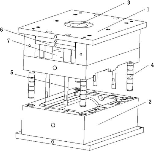
- Check 3D models (STL/STEP format): Focus on complex structures (e.g., deep grooves, thin walls, angled holes). Mark repeated machining surfaces (avoid missing features).
-
- Clarify usage: Functional testing (prioritize dimensional accuracy), appearance display (require smooth surfaces), or assembly verification (fit clearance within ±0.1mm).
-
- Note material: ABS/acrylic (plastics, prone to chipping), 6061 aluminum (common), 45# steel (hard, use conservative parameters).
- Equipment & Tool Check
-
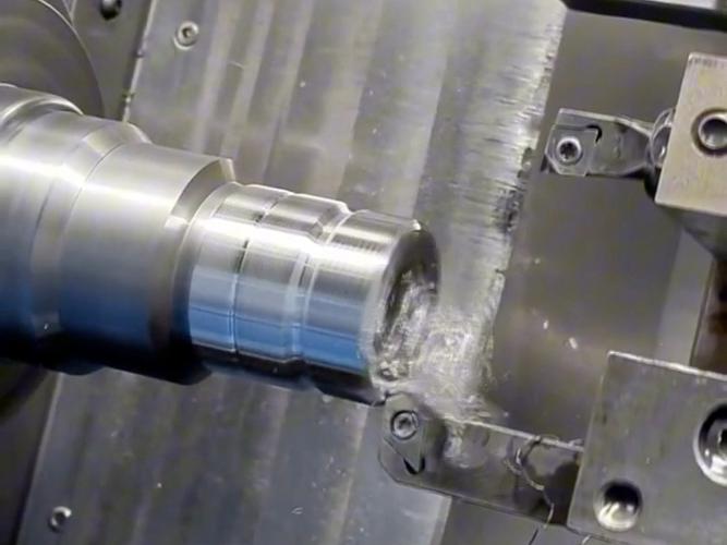
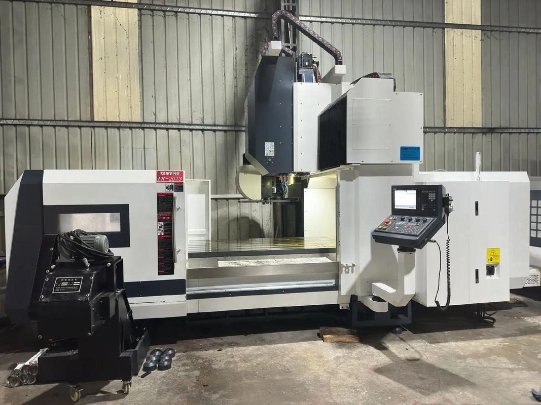
- Choose machine: Small parts → desktop CNC (travel ≤300mm); complex parts → vertical machining center (preferably with 4th axis).
-
- Test spindle: Idle for 1 minute. Check for abnormal noise; ensure smooth speed switching (e.g., 500→3000 RPM without jamming).
-
- Prepare supplies: Use kerosene for cooling plastics (anti-adhesion); emulsion for metals. Wear a mask (plastic dust irritates) and gloves (prevent scratches).
2. Workpiece Clamping (8 Minutes – Prevent Deformation/Shifting)
- Choose Fixture
-
- Small size (<100mm): Universal vise. Pad jaws with rubber (plastics) or aluminum sheets (metals).
-
- Thin sheets/irregular parts: Vacuum chuck (suction 0.5MPa; stick double-sided tape on plastics to prevent warping) or custom jigs (with locating blocks matching prototype contours).
- Clamping Steps
-
- Place workpiece stably. Hand-tighten the fixture to “slightly tight” (don’t leave marks on plastics).
-
- Roughly align with a ruler (edges parallel to machine X/Y axes, deviation <1mm – prototype accuracy is less strict than mass production).
-
- Gently wiggle the workpiece to confirm no looseness (key: clamp thin-walled parts at 1/3 length to avoid bending).
3. Tool Selection & Installation (5 Minutes)
|
Material
|
Machining Type
|
Recommended Tool
|
Tool Parameters
|
|
ABS/Acrylic
|
Contour/Plane Milling
|
HSS end mill (2-flute)
|
Diameter 3-10mm, flute length > machining depth
|
|
6061 Aluminum
|
Drilling/Grooving
|
Carbide tool (3-4 flutes)
|
Diameter 2-12mm, polished cutting edge
|
|
45# Steel
|
Rough/Finish Milling
|
Coated carbide tool (4-flute)
|
Diameter 5-16mm, helix angle 45°
|
- Tool overhang = machining depth + 5mm (too long causes vibration, scratching the prototype surface).
- Clean the tool holder. Tighten the collet with a wrench (note: don’t over-tighten HSS tools to avoid chipping).
4. Programming & Toolpath Setup (10 Minutes – Prioritize Fast Output)
- Software: Use UG or Mastercam. Select “prototype machining” template (default 0.05mm finish allowance).
- Toolpath Planning:
-
- Roughing: Use large-diameter tools (e.g., 10mm) for quick material removal. Cutting depth 1-3mm (for plastics, ≤1mm to prevent chipping).
-
- Finishing: Switch to small-diameter tools (e.g., 3mm) for corner cleaning. Slow feed by 50% (smoother surface).
- Simulation Check: Focus on fixture collisions and whether toolpaths cover all machining surfaces (prototypes often miss small features).
5. Tool Setting (5 Minutes – Adequate Accuracy)
- Z-axis Setting: For plastics, use the “paper method” (clamp thin paper at the tool tip; set Z=0 when the paper can be pulled out as the tip touches the workpiece). For metals, use a tool setter (error ≤0.02mm).
- X/Y-axis Setting: Touch workpiece edges with an edge finder, record coordinates (prototypes allow ±0.05mm error – no need for repeated checks).
- Confirmation: Manually move the tool to a safe position (≥30mm from the workpiece). Return to zero to verify coordinates.
6. Test Cutting & Machining (Time Depends on Size – Check First Piece)
- Test Cutting:
-
- Enable “single block mode,” cut the first feature (e.g., a hole/edge), then stop the machine.
-
- Measure dimensions with calipers (e.g., hole diameter, edge distance). Check surface (no burrs on plastics, no scratches on metals).
-
- Adjust parameters: Too many burrs → reduce feed; undersize → offset Z-axis by 0.03mm.
- Formal Machining:
-
- Start continuous run, stand by to observe: If plastics smoke → stop! Add kerosene. If metals make abnormal noise → stop! Tool may be dull.
-
- Clean chips every 10 minutes (use a vacuum for plastic chips, a brush for metal chips – don’t let them pile on the workpiece).
7. Inspection & Correction (5 Minutes)
- Key Checks:
-
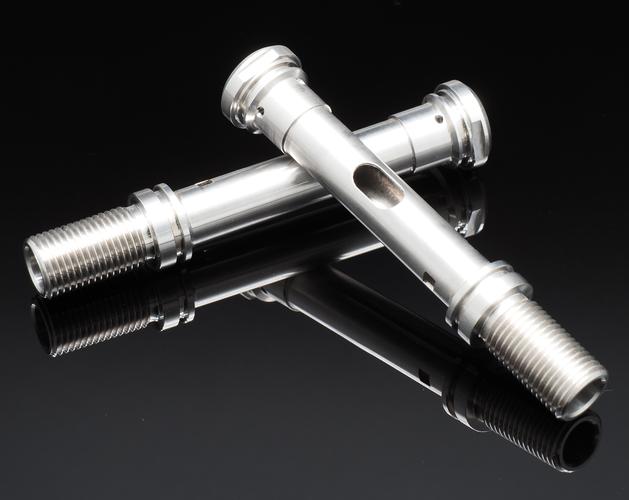
- Functional parts: Measure critical dimensions (e.g., shaft diameter, hole spacing). Use feeler gauges to check fit clearance.
-
- Appearance parts: Feel edges by hand (burr-free). Check surface (no obvious tool marks).
- Minor Fixes:
-
- Burrs: Lightly scrape with a utility knife (plastics) or sand with 800-grit sandpaper (metals).
-
- Within 0.1mm deviation: Ignore (prototypes allow small errors). Over deviation → re-program partial toolpaths for Repair Cutting.
8. Final Tasks (3 Minutes)
- Unload workpiece: Handle plastics gently (prone to cracking); wipe metals with a soft cloth (prevent fingerprints).
- Clean equipment: Vacuum chips thoroughly. Remove and store tools (apply anti-rust oil to HSS tools).
- Take notes: Write down effective speed/feed rates on the model drawing (reuse for the same material next time).
Disclaimer
- All information, opinions, and data contained in this article are for the purpose of information transmission only and do not constitute any advice on investment, transactions, law, medical care, or other matters.
- The content of the article is compiled based on public information or created based on the author’s personal understanding. Although every effort is made to ensure accuracy, it does not guarantee the completeness, accuracy, and timeliness of the information, nor does it bear any responsibility for any losses caused by the use of the content of this article.
- If the article involves third-party opinions, pictures, data, and other content, the copyright belongs to the original author. In case of infringement, please contact us for deletion.
- Readers should make independent decisions based on their actual situation and combined with professional opinions. The user shall bear all consequences arising from the use of the content of this article.

