CNC cutting tool failure can lead to dimensional drift, poor surface finish, scrapped parts and unplanned downtime. A broken or damaged tool is a symptom, not a complete root-cause diagnosis. This guide explains a structured method for classifying tool failure, collecting evidence, testing likely causes and verifying corrective actions before a revised process is released to production.
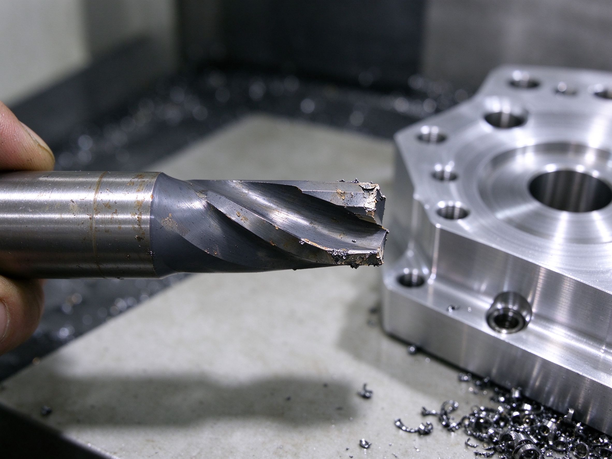
At a Glance
Tool failure is investigated from the damage pattern and machining evidence, not from a preset list of percentages. Tool grade, workpiece material, cutting parameters, runout, holder condition, overhang, workholding, coolant delivery, chip evacuation and toolpath strategy may all contribute. Corrective actions are verified against a baseline before the revised process is released.
What Counts as CNC Tool Failure?
| Condition | How it is treated | Next check |
|---|---|---|
| Uniform progressive flank wear | May be planned normal wear — wear alone is not a failure | Wear trend, set tool-life end point, part dimension and surface still conforming |
| Chipping or sudden breakage | Possible overload, vibration, runout, brittle edge, interrupted cut or chip evacuation | Tip and holder state, overhang, clamping, entry/exit, chip condition |
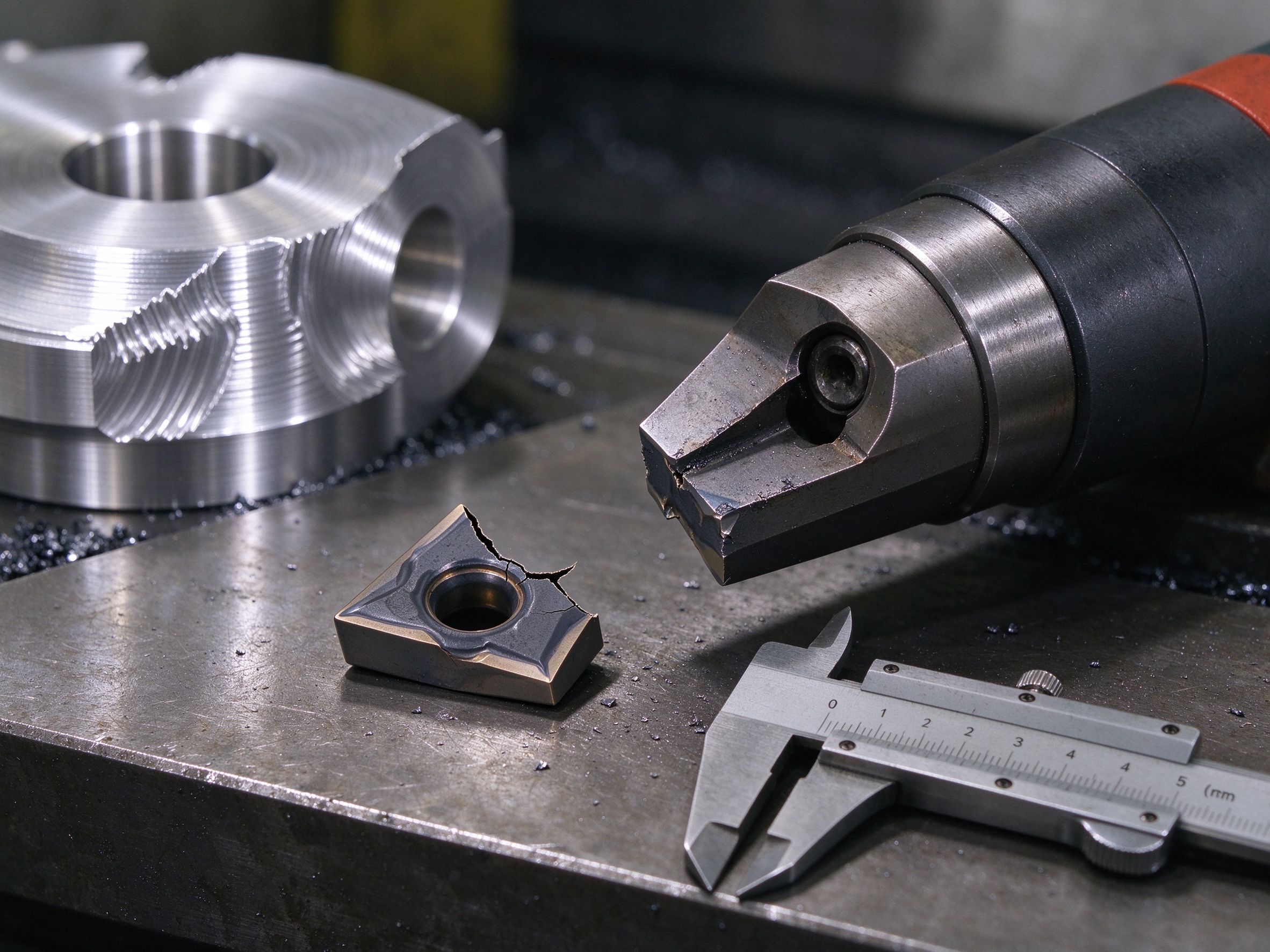
| Fine cracks on the edge | May relate to thermal cycling, temperature change and cooling | Intermittent coolant, temperature swings, tool grade suitability |
| Workpiece material sticking to the tip | Possible built-up edge or adhesion, not necessarily tool fracture | Workpiece material, edge geometry, lubrication, speed and feed |
| Sudden hole size or surface change | May relate to tool wear, runout, holder, deflection or machine condition | Tool state, runout, holder, measurement results and first-piece records |
Common CNC Cutting Tool Failure Modes
Failure is classified from the physical evidence before causes are proposed:
Fracture / sudden breakage
Tool separates or loses a large edge section during cut. Evidence includes overload marks, chatter, entry impact and interrupted cuts.
Chipping
Small pieces break off the edge. Related to edge strength, mechanical stability, runout, surface condition and cutting shock.
Thermal cracking
Fine cracks from temperature cycling and intermittent cooling. Confirm coolant continuity and cutting temperature changes.
Abnormal wear / built-up edge
Accelerated wear or material adhesion. Check material match, edge geometry, lubrication and the actual speed/feed window.
Root Causes of Premature Tool Failure
| Root-cause group | Evidence to collect | What not to assume |
|---|---|---|
| Tool selection & edge | Tool type, grade, coating, geometry, edge damage photos | "Carbide is harder" does not make it right for every cut |
| Cutting parameters | Actual spindle speed, feed per tooth, axial/radial depth, entry method | No universal tool life from a single feed or depth setting |
| Runout & holder | Tip runout, holder and collet state, clamping records | Do not blame parameters before runout is measured |
| Overhang & rigidity | Tool overhang, workpiece/fixture rigidity, chatter signs | Not all chatter is a tool material or coating problem |
| Coolant & chip evacuation | Coolant type, nozzle direction, supply, chip state, adhesion marks | More coolant pressure does not fix every heat or breakage case |
| Workpiece material & batch | Actual grade, hardness, heat treatment, blank surface, batch variation | Do not assume identical cutting response across batches |
| Program & toolpath | Entry/exit, path overlap, local load changes, program version | Speed and feed alone do not capture local toolpath loads |
A Step-by-Step Tool Failure Investigation Process
Stop & isolate
Remove the damaged tool from service; isolate and re-check affected parts if required.
Document evidence
Photo the damage; record tool type, workpiece material, program version and actual cutting conditions.
Check mechanics
Verify runout, holder, overhang, workholding, coolant and chip evacuation before judging parameters.
Form hypothesis
Propose the most likely cause from damage pattern and measurements.
Change one variable
Apply a controlled, measurable correction; avoid changing many parameters at once.
Verify & fix
Check first piece and the agreed number of following parts against the original baseline; fix the standard only after validation.
CNC Tool Failure Troubleshooting Matrix
| Observed symptom | Possible causes to check first | Correction to verify |
|---|---|---|
| Sudden tool breakage | Runout, clamping, overhang, actual load, interrupted cut, chip evacuation | Adjust overhang, clamping, entry method or cutting conditions for the confirmed cause |
| Rapid chipping | Mechanical stability, edge strength, entry impact, workpiece surface | Verify clamping, tool grade, edge geometry and feed per tooth |
| Thermal cracks | Temperature cycling, intermittent coolant, machining strategy | Stabilize coolant and conditions; evaluate a more suitable grade |
| Built-up edge | Workpiece material, edge geometry, lubrication, actual feed state | Adjust speed/feed within the manufacturer window; evaluate geometry and lubrication |
| Rapid wear | Actual cutting speed, material hardness, coating, contact time | Confirm the recommended window matches current material and method |
| Hole or key dimension drift | Tool state, runout, clamping, measurement method, temperature rise | Check compensation, in-process measurement, clamping and order; verify repeatability |
How to Verify Corrective Actions
Tool life is recorded as machining time, conforming part count, or time to a set wear end point. Breakage rate needs a clear denominator — per 1,000 tool hours, per 1,000 parts, or per 100 cycles. Tooling cost per good part states whether changeover, scrap, rework and downtime are included.
Record the original condition, change one main variable, check the first piece and the agreed number of following parts, then compare with the baseline. Only after validation is the new parameter or process fixed as the production standard.
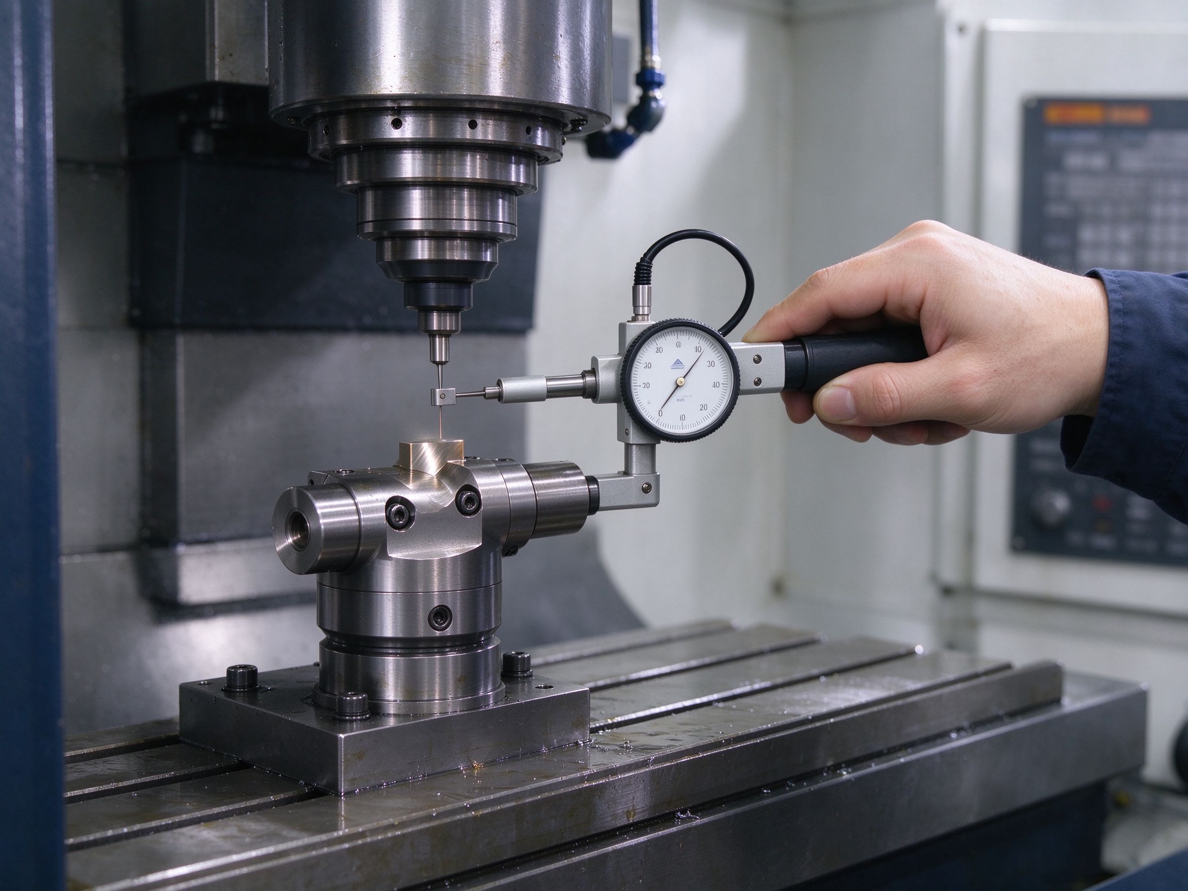
How Tool Failure Can Affect CNC Part Quality and Delivery
Dimensional drift
Wear or edge damage can affect some dimensions and features. The change depends on tool, operation, clamping and cutting conditions — not on a fixed rule.
Surface defects
Chipping, built-up edge and vibration can affect surface state. Material, clamping, parameters and coolant are checked alongside the tool.
Scrap & delivery risk
Sudden breakage can damage a workpiece or add downtime. Defined tool-life limits, inspection frequency and an abnormal-condition workflow reduce uncontrolled risk.
What CNC Buyers Should Ask Their Supplier
| Question | What it verifies |
|---|---|
| How are tool changes and tool-life limits recorded? | Whether process control is traceable per batch |
| How is a tool failure handled on the shop floor? | Whether affected parts are isolated and re-checked |
| What records are kept for dimensions and deviations? | Whether a part issue can be traced to tool, batch and inspection records |
| How is a recurring failure corrected? | Whether the supplier explains the cause and verifies the fix instead of only changing tools |
Frequently Asked Questions
Why does a CNC tool break suddenly?
What is the difference between tool wear and tool failure?
How do I troubleshoot chipping on a carbide tool?
Does a worn tool cause dimensional drift?
What information should a supplier provide after a tool-related quality issue?

Discuss a Machining or Quality Issue
Send your part drawing, tool information and observed problem. We will review the process evidence, propose a structured investigation and define verification steps for the correction.
Xiamen Goldcattle · Manufacturing since 1998 · CNC machining · Process control and inspection · Related: CNC machining services →