In precision manufacturing, the boundary between “a good part” and “a rejected batch” often traces back to a single decision: how many times the workpiece was removed and re-clamped between operations. Every setup change introduces the potential for positional error, tolerance stack-up, and increased lead time. CNC turning and milling — particularly when integrated into mill-turn or multi-process machining workflows — directly addresses this by combining rotational and multi-axis cutting operations on a single machine platform.
For engineers and procurement professionals sourcing complex parts with cylindrical features, prismatic faces, and tight concentricity requirements, the question is not “what is the difference between turning and milling?” but “can this supplier machine all my features with minimal setups and verified positional accuracy?”
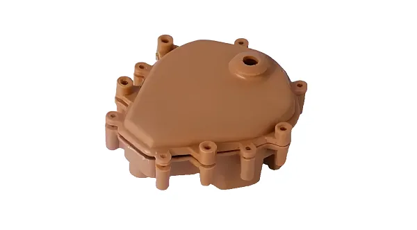
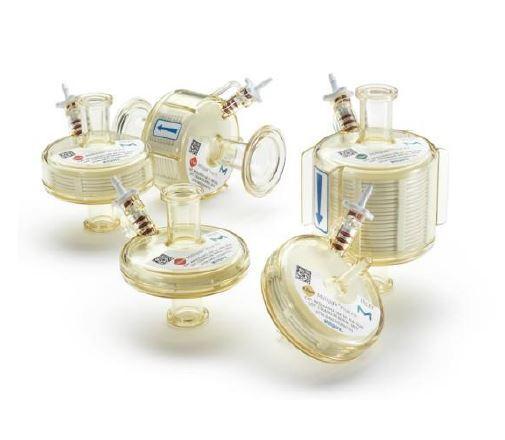
High-precision turned and milled parts with tight tolerance control
What Is CNC Turning and Milling?
CNC turning uses a rotating workpiece and stationary cutting tool to produce cylindrical or conical features — diameters, threads, grooves, tapers — with high concentricity and diameter precision. CNC milling uses a rotating cutting tool and stationary workpiece to create flat surfaces, slots, pockets, and complex 3D geometries via multi-axis movement (3-axis to 5-axis). When combined — either across coordinated machines or on a single mill-turn platform — they produce parts requiring both rotational symmetry and prismatic features without the cumulative error of multiple setups.
In summary, CNC turning and milling are complementary subtractive manufacturing processes — turning excels at cylindrical features with high diameter precision, while milling handles complex prismatic geometries — and their integration into coordinated or single-setup workflows is what determines the achievable positional accuracy and production efficiency for complex precision parts.
Why Combine CNC Turning and Milling?
The decision to combine turning and milling on a single part is an engineering decision, not a machine availability decision. When features on multiple axes must maintain tight positional relationships — a shaft diameter that must run concentric to a milled keyway, or a flange face that must be perpendicular to a turned bore — splitting these operations across separate machines introduces re-fixturing error.
Mill-turn machines and multi-tasking machining centers address this at the process level. By performing turning, milling, drilling, and tapping on a single platform, they eliminate the need to transfer workpieces between machines — each transfer being a potential source of datum loss, clamping variation, and non-value-added handling time.
Industry trends show that the global CNC turn-mill machine market size was approximately USD 943 million in 2025, and is projected to reach USD 1.278 billion by 2032, with a compound annual growth rate (CAGR) of about 4.5%. Meanwhile, multi-tasking machines can complete multiple machining operations in a single setup, significantly reducing setup times, shortening delivery lead times, and improving accuracy.
| Benefit | Engineering Mechanism | Procurement Impact |
|---|---|---|
| Fewer setups | Single-platform turning + milling operations eliminate workpiece transfer between machines | Reduced positional error accumulation; fewer fixtures required; 35% production time reduction achievable for parts needing both cylindrical and cross-drilled features |
| Better concentricity | Features machined on a common datum without re-clamping maintain inherent coaxial alignment | Tighter GD&T compliance on runout and position callouts; reduced assembly rejection rate |
| Shorter lead time | Sequential operations consolidated into overlapping or simultaneous machining cycles | Faster time-to-first-article; reduced work-in-process inventory |
| Lower handling risk | No manual part transfer between turning and milling workstations | Eliminated handling damage; consistent process control across all features |
The key factor driving adoption of combined CNC turning and milling is not machine sophistication alone — it is the engineering reality that every workpiece transfer between separate machines introduces potential datum loss, clamping variation, and positional error, while integrated mill-turn machining on a common datum eliminates these variables and directly improves tolerance compliance on complex parts.
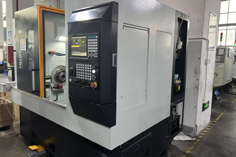
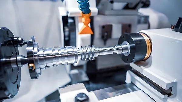
Industrial CNC mill-turn machine for integrated multi-process machining
CNC Turning vs CNC Milling — Performance Comparison
To help engineers and procurement professionals make informed decisions, we’ve compiled a structured performance comparison between the two core processes:
| Comparison Dimension | CNC Turning | CNC Milling |
|---|---|---|
| Workpiece motion | Workpiece rotates; cutting tool feeds linearly | Cutting tool rotates; workpiece moves along controlled axes |
| Best geometry | Cylindrical, conical, and rotationally symmetric parts | Prismatic, flat, angled, and complex 3D surfaces |
| Key advantage | Superior diameter precision and concentricity from continuous rotational cutting | Multi-axis versatility for non-cylindrical features |
| Typical tolerance | ±0.005mm on diameter (precision application) | ±0.005mm achievable depending on geometry, fixturing rigidity, and machine calibration |
| Typical surface finish | Ra 0.4–0.8μm standard | Ra 0.8–1.6μm standard |
| Typical applications | Shafts, bushings, pins, valves, connectors | Brackets, housings, gear teeth, engine blocks |
| Process limitation | Limited to rotationally symmetric features | Cylindrical features require rotary axis or additional setup |
In high-precision environments, CNC milling can achieve tolerances within a few microns — for example, around ±0.005mm — depending on feature geometry, fixturing rigidity, machine calibration, and overall process control. Turning is the most direct route to accurate, repeatable round features with excellent concentricity and strong throughput from bar stock.
Lot size and tolerance requirements should be the primary determinants of machine tool selection when choosing between turning, milling, or a combined approach.
In summary, CNC turning is optimized for round, rotationally symmetric parts with superior diameter precision (commonly ±0.005mm) and concentricity from continuous rotational cutting, while CNC milling excels at prismatic and complex 3D geometries — and the decision between them should be driven by part geometry, tolerance requirements, and production volume rather than machine availability.
Tolerance & Repeatability Capabilities
For procurement professionals evaluating machining suppliers, tolerances and repeatability are the most critical performance metrics — directly determining part fit, assembly yield, and field reliability. Precision turned and milled parts require tolerances that can range from ±0.005mm to ±0.05mm, with achievable precision depending on part geometry, material, and process integration.
Tolerance Capability by Process
| Process | Standard Tolerance | Precision Tolerance | High-Precision Tolerance |
|---|---|---|---|
| CNC Turning (diameter) | ±0.05mm | ±0.01mm | ±0.005mm |
| CNC Turning (length) | ±0.05mm | ±0.01mm | ±0.01mm |
| CNC Milling (linear) | ±0.1mm | ±0.05mm | ±0.01mm |
| Mill-Turn (positional) | ±0.05mm | ±0.01mm | ±0.005mm |
| 5-Axis Milling | ±0.05mm | ±0.01mm | ±0.005mm |
Market data shows that high-end CNC milling can achieve ±0.005mm precision, depending on feature geometry, fixturing rigidity, and machine calibration conditions. For European manufacturers, selecting a machining supplier is no longer just about cost — compliance, technical precision, delivery reliability, and long-term partnership are equally important.
Tolerances achievable on combined turning-and-milling features depend on the number of setups: parts machined in a single mill-turn setup can maintain positional relationships between turned and milled features within ±0.005mm, while parts transferred between separate turning and milling centers typically experience an additional ±0.01–0.02mm of positional uncertainty from re-fixturing.
Repeatability: The Production Metric That Matters Most
Absolute precision on a single prototype is not the same as repeatable precision across a production batch. Positional repeatability for industrial-grade CNC equipment ranges from ±0.002mm to ±0.005mm, translating to true batch-to-batch consistency. The three variables that most affect repeatability in combined turning-and-milling production are:
- Thermal stability: Spindle and ball screw thermal growth during continuous operation causes dimensional drift. Machine warm-up cycles and temperature-controlled workshops (±2°C) are essential for tight-tolerance production.
- Tool wear management: As cutting tools degrade, dimensions gradually drift. In-process probing and scheduled tool changes prevent quality degradation during long production runs.
- Fixture precision: Even with perfect machine repeatability, inconsistent workpiece clamping introduces variation. Precision soft jaws and dedicated fixtures are critical for repeatable part location — particularly important when parts move between turning and milling stations.
In summary, CNC turning and milling tolerance capability ranges from ±0.05mm for standard features to ±0.005mm for precision applications — but the more important metric for production buyers is repeatability, which depends on thermal management, tool wear control, and fixturing precision across every part in the batch, not just the first article.
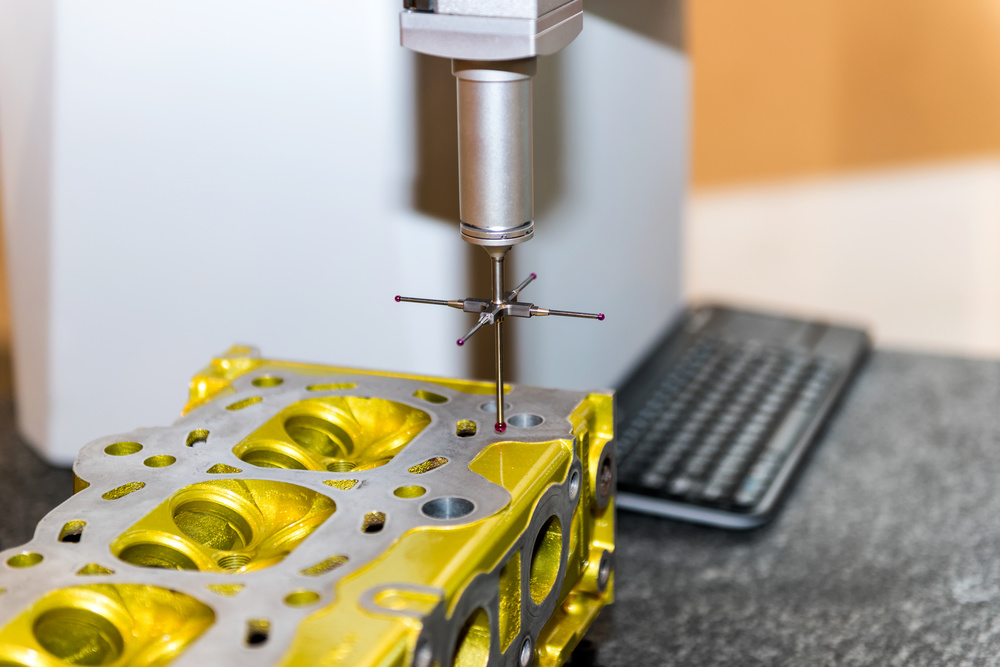
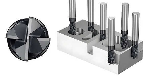
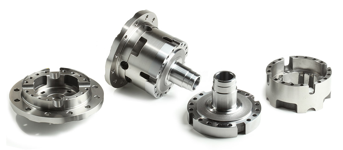
Coordinate Measuring Machine (CMM) inspection for dimensional verification of critical features
Manufacturing Capabilities — Equipment & Processes
CNC Turning Equipment
| Machine Type | Capability | Key Specifications | Best For |
|---|---|---|---|
| 2-Axis CNC Lathes | Standard turning: diameters, threads, grooves, tapers | Spindle speeds 3,000–10,000 RPM | Simple shafts, bushings, pins |
| 4-Axis Live-Tooling Lathes | Turning + milling features (cross-holes, flats, keyways) in one setup | Y-axis milling attachment; driven tool stations | Parts needing both cylindrical shapes and prismatic features |
| Swiss-Type Lathes | Ultra-precision turning for micro-parts | Sub-10mm diameter capability; sliding headstock | Medical devices, watch components, micro-connectors |
| Large-Format Turning | Heavy turning for industrial components | Up to 1m diameter; extended bed length | Hydraulic cylinders, large shafts, marine components |
Our 4-axis turning centers can complete turning and cross-hole drilling in a single operation, improving production efficiency by up to 35%.
CNC Milling Equipment
| Machine Type | Capability | Key Specifications | Best For |
|---|---|---|---|
| 3-Axis CNC Mills | Flat surfaces, slots, pockets, holes | Standard vertical machining center | Brackets, plates, simple prismatic parts |
| 4-Axis CNC Mills | 3-axis + rotation around A-axis | Rotary table for angled features | Parts with side holes or angled faces |
| 5-Axis CNC Mills | Multi-face machining in one setup; complex curved surfaces | Simultaneous 5-axis movement; tilting rotary table | Aerospace structural, medical implants, complex housings |
| Large-Format Milling | Heavy prismatic machining | Workpieces up to 2m length | Industrial machinery frames, large housings |
5-axis milling can complete all machining of complex curved surfaces in a single setup, eliminating the positioning error accumulation caused by traditional multiple setups.
Integrated Capabilities
- Mill-Turn Machining: Turning, milling, drilling, and tapping performed on a single platform — eliminating workpiece transfer, maintaining common datums, and preserving concentricity between turned and milled features
- Material Range: Aluminum (6061/7075), stainless steel (304/316), titanium (Ti-6Al-4V), carbon steel, alloy steel, brass, engineering plastics (PEEK, nylon, acrylic), carbon fiber-reinforced polymers
- Quality Verification: CMM dimensional inspection on all critical features; 3D scanning for complex geometry verification; AS9100D-compliant inspection for aerospace parts with 100% dimensional verification
- Certifications: ISO 9001, ISO 13485, AS9100D — ensuring quality management system compliance across industrial, medical, and aerospace sectors
From 2-axis turning of simple shafts to 5-axis simultaneous milling of complex aerospace structures — with mill-turn integration available for parts requiring both cylindrical precision and prismatic versatility — our equipment portfolio supports the full spectrum of precision machining requirements under one quality management system.
Engineering Challenges in Combined Turning & Milling
These are the real-world challenges that separate experienced multi-process machining suppliers from shops that simply own a lathe and a mill. Each failure mode is preventable through systematic process engineering — but only when the supplier understands the interaction between turning and milling operations, not just each process in isolation.
| Challenge | Root Cause | Commercial Impact | Solution |
|---|---|---|---|
| Re-fixturing positional error | Workpiece transferred between separate machines; datum shift during re-clamping | Feature misalignment; GD&T violations; assembly rejection | Mill-turn single-setup machining; common datum strategy; CMM verification |
| Concentricity deviation | Separate setups for turning and milling; inconsistent clamping force | Bearing/seal failure; vibration in rotating assemblies | Common datum single setup; in-process probing; dedicated soft-jaw fixturing |
| Thermal drift during long runs | Spindle operation causing thermal expansion of machine structure | Dimensional drift across batch; inconsistent part quality | Machine warm-up cycles; temperature-controlled workshop; automatic offset compensation |
| Tool deflection on slender parts | High length-to-diameter ratio; insufficient tool rigidity | Taper in diameters; surface chatter; out-of-tolerance features | Steady rests; optimized tool holder selection; validated cutting parameters |
| Thin-wall vibration | Insufficient wall thickness; resonance between cutting frequency and part natural frequency | Poor surface finish; dimensional inaccuracy; part deformation | Optimized cutting parameters; custom soft jaws; harmonic analysis to avoid resonance |
| Burr formation at process transitions | Tool exit on feature interfaces; material ductility | Assembly interference; extra deburring time; cosmetic rejection | Programmed edge break; dedicated finishing passes; standard deburring protocol |
The key factor distinguishing experienced combined turning-and-milling suppliers from general machine shops is not equipment ownership — it is the systematic engineering approach to managing re-fixturing error, concentricity preservation, thermal stability, and process-transition quality that determines whether complex multi-feature parts meet specification across production batches.
DFM for Multi-Process Machining
Design for Manufacturability(DFM)in the context of combined turning and milling is fundamentally about reducing the number of setups and ensuring that critical feature relationships are machined from common datums.
DFM Principles for Turned-and-Milled Parts:
- Datum consolidation: Designate a single datum surface that can be accessed by both turning and milling operations — ideally a precision-turned diameter or face that serves as the reference for all subsequent features
- Feature grouping: Group features that share tight positional relationships so they are machined in the same setup — for example, a bearing diameter and its adjacent shoulder face should be turned in one operation, and milled bolt holes that must be concentric to that diameter should be machined on a mill-turn platform without unclamping
- Tolerance optimization: Apply tight tolerances only where functionally required. The tighter the tolerance, the higher the machining cost — going from ±0.001″ to ±0.00025″ can cost approximately four times as much. Over-specifying tolerances on non-critical features drives up machining time and cost without adding functional value
- Accessibility analysis: Ensure that both turning tools and milling cutters can reach all features without interference; deep bores may require extended tooling in turning, while deep pockets may require long-reach end mills in milling
- Material-specific strategy: Different materials demand different turning and milling parameters. Stainless steel work-hardens and requires higher cutting forces, titanium concentrates heat at the cutting edge, and aluminum allows aggressive material removal rates — each influencing whether separate or combined processing is optimal
Our DFM review — delivered within 24–48 hours of CAD receipt — analyzes part geometry to recommend the optimal process sequence: which features should be turned, which should be milled, and whether mill-turn integration can reduce setups, improve accuracy, or lower total machining cost.
In summary, DFM for combined turning and milling is an exercise in setup reduction and datum preservation — the goal is to machine features that share tight positional relationships from a common datum in the minimum number of setups, eliminating the re-fixturing errors and tolerance stack-up that drive machining cost and quality risk.
Case Study — Precision Shaft Housing with Multi-Feature Accuracy
Project: Precision Shaft Housing for Industrial Pump Assembly
Industry: Industrial Machinery — Fluid Handling
Material: 316 Stainless Steel
Challenge: The shaft housing required a precision-turned internal bore (Ø50mm ±0.005mm, Ra 0.4μm) that had to be perfectly concentric to an externally milled flange face and bolt circle pattern (8× M8 threaded holes on Ø80mm PCD). Using separate turning and milling centers created a concentricity deviation of up to 0.03mm between the bore axis and the bolt circle center after re-fixturing — exceeding the ±0.01mm position tolerance specified on the drawing. Production volume: 5,000 units annually.
Our Solution:
- Recommended mill-turn single-setup machining to perform bore turning, flange facing, bolt circle drilling, and thread milling on a common datum without unclamping
- Designed dedicated soft-jaw fixturing to maintain clamping force consistency and prevent bore distortion during machining
- Implemented in-process probing cycle to verify bore-to-bolt-circle concentricity before tool retraction — enabling real-time offset correction within the same setup
- Applied validated machining strategy optimized for 316 stainless steel work-hardening characteristics
Results:
- Bore-to-bolt-circle concentricity: ±0.008mm average (within the ±0.01mm specification)
- Surface finish on bore: Ra 0.35μm (better than Ra 0.4μm requirement)
- Production lead time: reduced by 30% compared to separate turning + milling workflow (eliminated one setup, one transport, and one queue wait between workstations)
- First-article pass rate: 100% across both bore tolerance and positional callouts
- Annual production: 5,000 units delivered with zero dimensional non-conformances over 18 months
This project demonstrates the core value proposition of integrated CNC turning and milling: when features sharing tight positional relationships are machined in a single setup from a common datum, the concentricity errors inherent in multi-setup processing are eliminated — directly improving part quality, reducing inspection time, and shortening production lead time.
Supplier Selection Criteria — What to Look for in a Turning & Milling Partner
Selecting a CNC turning and milling supplier for complex multi-feature parts requires evaluating more than machine specifications and unit price. The difference between a supplier who produces conforming parts consistently and one who produces intermittent non-conformances often lies in process integration capability — not equipment brand.
Engineering-Focused Evaluation Criteria:
- Process Integration Capability — Does the supplier have mill-turn or multi-tasking equipment that can perform turning and milling on a common datum, or do they rely on transferring parts between separate machines? Single-setup capability directly predicts concentricity and positional accuracy outcomes.
- Precision & Tolerance Documentation — Ask for a capability statement or machine list. Reputable precision machining suppliers specializing in milling, turning, and rapid prototyping will share this information upfront as a matter of course. Request sample inspection reports — not just the tolerance they claim, but the tolerance they can prove with CMM data.
- Material & Process Versatility — Verify that the supplier has documented experience with your specific material and can perform secondary operations (threading, deburring, surface finishing) in-house rather than outsourcing them — each outsourced step introduces variability and lead time risk.
- Quality Certifications & Compliance — ISO 9001 is the baseline for general industrial quality management. For aerospace: AS9100D. For medical devices: ISO 13485. Verify that certifications are current and cover the specific processes required for your parts.
- DFM & Engineering Support — Does the supplier provide DFM feedback before production — recommending which features should be turned versus milled, identifying potential tolerance conflicts, and suggesting cost reduction through setup consolidation? Proactive DFM engagement separates production partners from job shops.
- Scalability & Lead Time Reliability — Can the supplier handle both prototype quantities (1–50 parts) and production volumes (1,000–50,000+)? Does the supplier provide confirmed delivery dates at quoting stage and consistently meet them?
In summary, selecting a CNC turning and milling partner requires evaluating process integration capability(mill-turn vs. separate machines), documented precision(CMM data, not claims), material expertise, quality certifications, DFM support, and production scalability — with the most critical factor being whether the supplier can machine features sharing tight positional relationships from a common datum in a single setup.
FAQ — CNC Turning and Milling
Q1: What is the difference between CNC turning and milling?
CNC turning rotates the workpiece against a stationary cutting tool to create cylindrical or conical features — optimized for diameters, threads, grooves, and tapers with high concentricity. CNC milling rotates the cutting tool against a stationary workpiece to create flat surfaces, slots, pockets, and complex 3D geometries via multi-axis movement. The fundamental difference is motion: turning is workpiece-rotation-driven, milling is tool-rotation-driven.
Q2: What are the advantages of mill-turn machining?
Mill-turn machining performs turning, milling, drilling, and tapping on a single machine platform without unclamping the workpiece. This eliminates re-fixturing errors, preserves concentricity between turned and milled features, reduces total setup time, and shortens production lead time. For parts where features on multiple axes must maintain tight positional relationships — such as a bearing bore that must be concentric to a bolt circle — mill-turn single-setup processing can reduce positional deviation by 50–70% compared to separate turning and milling operations.
Q3: What tolerances can CNC turning and milling achieve?
Standard CNC turning achieves ±0.05mm on diameter; precision turning achieves ±0.01mm; high-precision turning with calibrated equipment can reach ±0.005mm. CNC milling achieves ±0.1mm standard, ±0.05mm precision, and ±0.01mm high-precision — with ±0.005mm achievable under optimal conditions depending on feature geometry, fixturing rigidity, and machine calibration. Mill-turn single-setup processing maintains positional relationships between turned and milled features within ±0.005mm by eliminating re-fixturing errors.
Q4: Which process is more accurate — turning or milling?
CNC turning typically achieves tighter tolerances on diameter and roundness features because the continuous rotational cutting motion provides inherent stability and the cutting tool experiences consistent loading. CNC turning is the most direct route to accurate, repeatable round features with excellent concentricity. CNC milling can achieve comparable precision — down to ±0.005mm in high-precision environments — but requires more careful management of fixturing rigidity, tool deflection, and multi-axis positioning accuracy. For cylindrical precision, turning is generally preferred; for complex geometry precision, milling excels.
Q5: Why is setup reduction important in precision machining?
Every time a workpiece is removed from one machine and re-clamped in another, the potential for positional error is introduced through datum shift, clamping force variation, and alignment tolerance. A single setup error of 0.01mm can cascade into a positional tolerance violation when multiple features are involved. Reducing setups — through mill-turn or multi-tasking machining — directly improves tolerance compliance and reduces inspection burden on features with tight GD&T positional callouts.
Q6: What materials can be processed with combined turning and milling?
Combined turning and milling can process virtually all engineering metals and many engineering plastics. Common materials include aluminum alloys (6061, 7075), stainless steels (304, 316), titanium alloys (Ti-6Al-4V), carbon and alloy steels, brass, and engineering plastics (PEEK, nylon, acrylic). The material selected determines the optimal cutting parameters, tooling, and whether separate or combined processing is more efficient.
Q7: How does DFM reduce the cost of turned and milled parts?
DFM (Design for Manufacturability) analysis reduces cost by identifying opportunities to consolidate setups, optimize tolerances, and simplify feature geometry before machining begins. The principle is straightforward: the tighter the tolerance, the higher the machining cost. Applying tight tolerances only where functionally required — while allowing standard tolerances elsewhere — can significantly reduce machining time and cost without compromising part function. Proactive DFM analysis also identifies potential manufacturability issues (thin walls, deep features, inaccessible geometries) before tooling commitment, avoiding costly rework.
Q8: What quality certifications should a CNC turning and milling supplier have?
The minimum baseline is ISO 9001 for general industrial quality management. For aerospace applications, AS9100D certification ensures compliance with the additional quality and traceability requirements of the aerospace industry. For medical device components, ISO 13485 is the relevant quality management standard. Beyond certifications, ask to see sample inspection reports and CMM data — documentation of actual measured performance carries more weight than a certificate on the wall. A qualified precision machining supplier will share capability statements and machine lists as a matter of standard practice.
Ready to machine your complex turned and milled parts?
Upload your CAD file for a free DFM review.
- → Receive process recommendation within 24–48 hours
- → Get quote with tolerance and lead time confirmation
- → Single-setup mill-turn available for critical concentricity features
Our Commitment to Quality
Precision
Turning tolerances to ±0.005mm; Milling tolerances to ±0.01mm; Mill-turn positional accuracy to ±0.005mm
Inspection
CMM dimensional verification; 3D scanning for complex geometries; AS9100D-compliant 100% inspection for aerospace parts
Equipment
2-axis to 4-axis live-tooling CNC lathes; Swiss-type lathes; 3-axis to 5-axis CNC mills; mill-turn multi-tasking platforms
Materials
Aluminum (6061/7075), Stainless Steel (304/316), Titanium (Ti-6Al-4V), Brass, Engineering Plastics, Composites
Certifications
ISO 9001, ISO 13485, AS9100D
Documentation
CMM dimensional reports; material certifications; FAI reports; full PPAP available