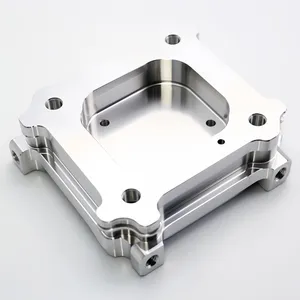
A 3D model is a digital three-dimensional representation of an object created using CAD or 3D modeling software. In manufacturing, 3D models define geometry, dimensions, tolerances, and design features that guide CNC machining, 3D printing, mold making, and engineering analysis, serving as the universal digital language for modern production.
✅ Digital geometry representation
✅ Core of manufacturing workflow
✅ Supports CAD/CAM integration
✅ Multiple standard file formats
Core Definition of a 3D Model
At its core, a 3D model is built from mathematical geometry data that defines an object’s vertices, surfaces, and solid properties. Unlike traditional 2D drawings, it captures full spatial information that machines can read directly, eliminating manual interpretation errors. For manufacturing teams, this means a single digital file can drive the entire production process, from design to inspection.
Types of 3D Models for Manufacturing
Not all 3D models are the same. For industrial production, models are categorized by their data structure, each tailored to specific manufacturing needs:
Solid Models
The most common type for engineering manufacturing, solid models define the full volume of an object with precise mathematical data. They preserve dimensional information, tolerances, and assembly relationships.
Common Files: STEP, Parasolid
Best For: CNC machining, injection mold making
Surface Models
Surface models define the outer skin of an object using mathematical curves, ideal for complex, smooth geometries that solid models struggle to capture.
Common Files: IGES
Best For: Complex mold cavities, automotive body panels
Mesh Models
Mesh models approximate an object’s surface using a grid of small triangles. They are simpler in structure but lack the precise dimensional data of solid models.
Common Files: STL, OBJ
Best For: 3D printing, visualization, prototyping
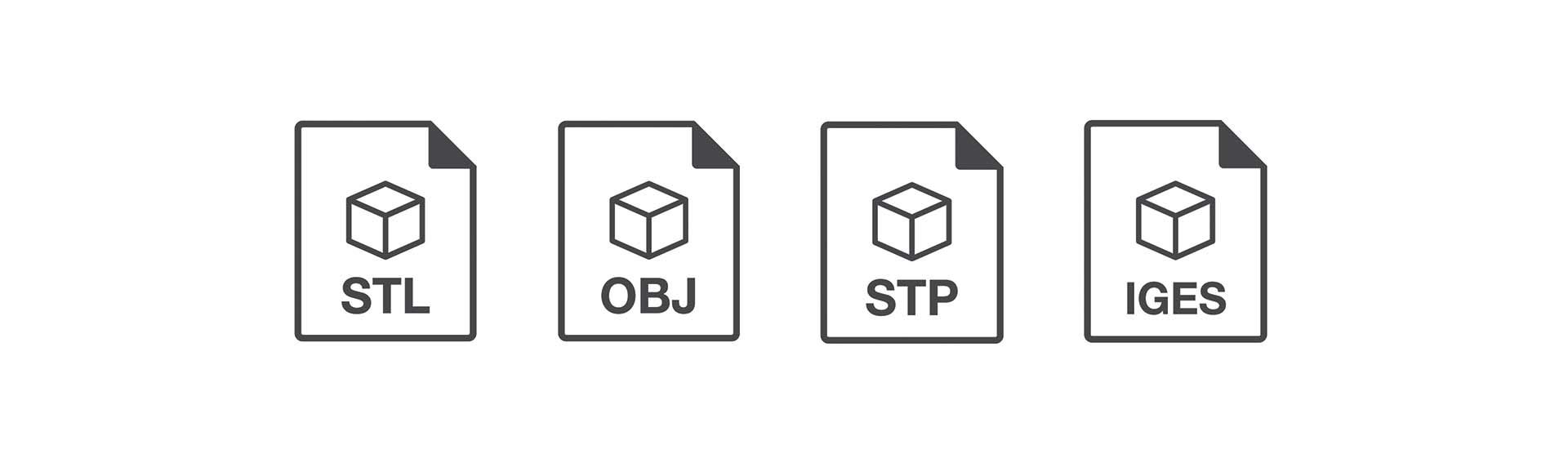
Common 3D Model File Formats for Manufacturing
Choosing the right file format is critical to ensure your 3D model can be used for production without data loss. For B2B procurement teams, understanding these formats helps you avoid delays and miscommunication with your supplier.
Which file format is best for manufacturing?
For most precision manufacturing projects like CNC machining, STEP files are typically preferred. They preserve full solid geometry, dimensional information, and assembly data, making them the universal standard for engineering production. This ensures we can accurately interpret your design and produce parts that match your exact specifications.
At Goldcattle, we support all common industrial 3D file formats, including STEP, IGES, STL, OBJ, and DWG/DXF, to ensure seamless collaboration regardless of your CAD tool.
How 3D Models Are Used in Manufacturing
For modern manufacturing, 3D models are not just design files—they drive the entire production workflow, from initial concept to final quality inspection. This end-to-end digital thread reduces errors, cuts lead time, and ensures consistent part quality.
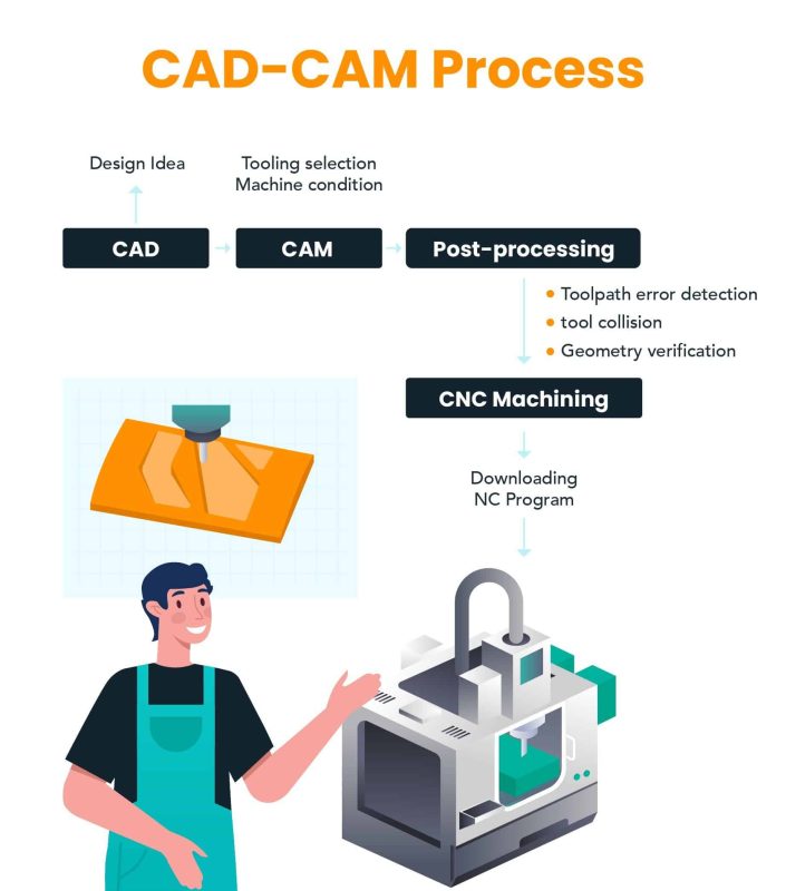
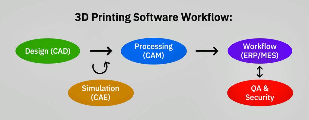
The CAD-to-Production Workflow
- CAD Design: Engineers create the 3D model, defining dimensions, materials, and tolerances based on product requirements.
- CAM Programming: The 3D model is imported into CAM software, where we generate toolpaths for CNC machines or slicing instructions for 3D printers.
- Simulation: We run virtual simulation on the model to test for tool collision, deformation, and process feasibility before production starts.
- Production: The machine reads the digital instructions directly from the 3D model, producing the physical part with high precision.
- Inspection: We use the original 3D model as a reference to inspect the finished part, verifying that all dimensions match the design.
Common Problems with 3D Models for Manufacturing
Even with the right file format, flawed 3D models can cause production delays, increased cost, or failed parts. Our engineering team often sees these common issues when reviewing customer designs:
- Non-manifold Geometry
Geometry with invalid edges or overlapping faces that machines cannot interpret. This can cause CAM software to fail to generate toolpaths, or 3D printers to produce incomplete parts.
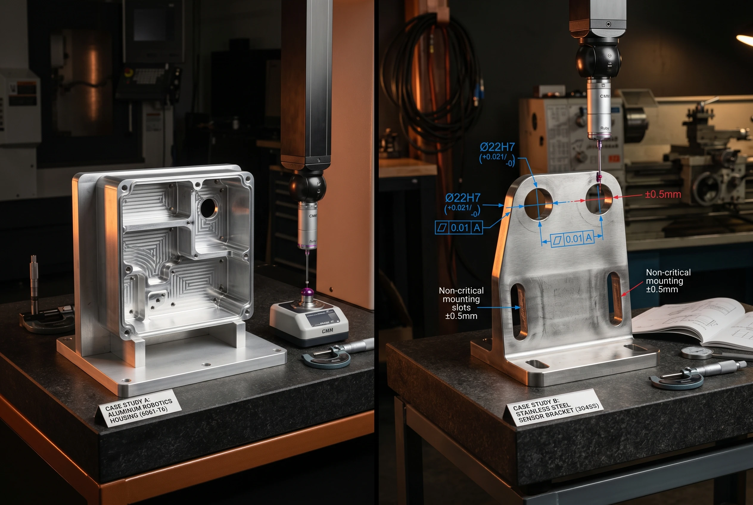
- Missing Dimensions or Tolerances
Models without clear critical dimension markings force manufacturers to make assumptions, which can lead to parts that don’t fit your assembly.
- Too-Thin Walls
Walls thinner than 0.8mm for metals or 1.5mm for plastics are prone to deformation during CNC machining, or breakage during 3D printing.
- Over-Complex Geometry
Unnecessarily tight tolerances or micro-features that require special tools, increasing production cost and lead time without functional benefit.
This is why a professional DFM (Design for Manufacturability) review is so valuable. Our team can catch these issues before production starts, helping you optimize your design to reduce cost and avoid delays.
What 3D Model Do Manufacturers Need for Quotation?
When you request a quote for custom manufacturing, providing the right 3D model helps us give you an accurate, fast quote and avoid back-and-forth communication. For most projects, we recommend uploading:
STEP Files
Our preferred format for CNC and mold projects, as it preserves all precision engineering data for accurate quoting.
IGES Files
A great alternative for legacy CAD designs or complex surface models that use older CAD tools.
STL Files
Perfect for 3D printing projects, or when you only need a quick prototype quote based on mesh geometry.
2D Drawings
If you only have 2D drawings, we can work with those too, though a 3D model helps us deliver faster, more accurate results.
Frequently Asked Questions
What is a 3D model?
A 3D model is a digital three-dimensional representation of an object, built from mathematical geometry data. In manufacturing, it acts as the universal digital file that drives the entire production process, from design to inspection.
Is a 3D model the same as CAD?
No. CAD (Computer-Aided Design) is the software and process used to create engineering 3D models. A 3D model is the output of CAD software—the digital file that contains the object’s geometry and specifications.
What file format is best for CNC machining?
STEP files are the preferred format for CNC machining, as they preserve full solid geometry, dimensions, and tolerance information, ensuring we can produce your part with high precision.
Can STL files be used for CNC machining?
While STL files can be used for basic CNC work, they are not ideal. STL files only contain mesh surface data, not the precise dimensional and tolerance data that solid models like STEP have, which can lead to accuracy issues for precision parts.
How accurate are 3D models for manufacturing?
Engineering 3D models can be extremely accurate, with dimensional precision down to micron levels. When paired with precision manufacturing equipment like our 5-axis CNC machines, we can produce parts that match the model within ±0.005mm tolerance.
Can manufacturers create a 3D model from a drawing or image?
Yes! If you only have a 2D drawing or even a photo of a part, we can reverse-engineer it to create a production-ready 3D model. Learn more about our photo to 3D model service.