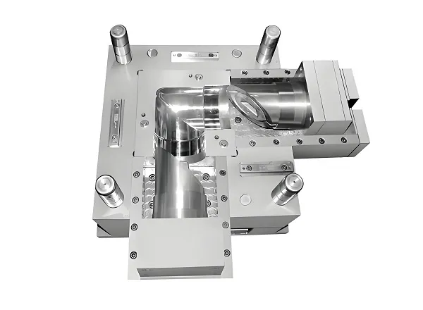
Injection Mold Solution · Gardening & Planter Products
Custom Balcony & Bonsai Plastic Mold
Custom injection molds for balcony planters, bonsai pots, flower pots, nursery pots and related plastic gardening containers — engineered from drainage features and wall thickness to cooling, ejection and T1 approval.
- Founded in 1998Mold making and injection molding in one facility
- Six in-house processesMold making, injection molding, CNC, die casting, 3D printing, sheet metal
- ISO 9001:2015Documented process control
Balcony & Bonsai Plastic Mold Overview
A planter mold is not a generic container tool. Balcony planters, bonsai pots and nursery pots share a set of structural features — thin tapered walls, a reinforced rim, drainage openings, ribs for stacking strength and often a decorative exterior — that determine how the cavity, core, gating, cooling and ejection have to be arranged. This page covers how those molds are engineered, what configuration options exist, how the tooling is manufactured and inspected, and what a buyer needs to prepare before requesting a quotation.
The product scope of this mold program covers:
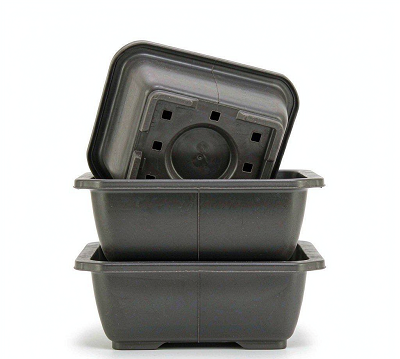
Balcony Planters
Rectangular and trough-style containers for railing and ledge mounting, often with integrated water reservoir or saucer interfaces.
Bonsai Pots
Rigid shallow pots with drainage patterns, rim geometry for wiring the root ball, and decorative exterior finishes.
Nursery Pots
High-volume tapered containers designed for stacking, transport efficiency and automated de-nesting on filling lines.
Decorative Planters
Appearance-driven containers where surface texture, color consistency and parting-line placement are acceptance criteria.
Scope note. This page describes the mold and the mold engineering for these products. Molding production, secondary operations and assembly can be quoted together with the tool or separately, depending on the program.
Custom Mold Configurations
Configuration is decided from annual volume, part size, press availability and budget. The table below shows the options available and what each one is actually for.
| Configuration | What it means | When it is the right choice |
|---|---|---|
| Single cavity | One part per shot. | Design validation, low annual volume, large planters where a multi-cavity tool would exceed press capacity. |
| Multi cavity | Two or more identical cavities producing the same part per shot. | Volume is high enough that the added tooling cost is recovered through lower per-part cost. |
| Family mold | Different parts in one tool, typically a planter together with its matching saucer or tray. | Matched sets where both parts run in the same color and the fill balance can be controlled. |
| Cold runner | Runner solidifies with the part and is separated after molding. | Lower tooling cost, easier color changeover, wide processing window; suited to short and medium runs. |
| Hot runner | Melt is kept molten in a heated manifold up to the gate. | High volume runs where runner waste and cycle time dominate; justified by material savings and consistency. |
| Prototype / bridge tool | Simplified tool, often single cavity with reduced steel hardness. | Samples, market testing, pilot production before committing to a hardened production tool. |
How cavity count is decided
Cavity count is a cash-flow decision, not a technical one. Adding cavities increases tooling cost and lead time roughly in proportion to the added steel and machining, while reducing the per-part cost by spreading the same cycle across more parts. The break-even sits where the annual volume is large enough that the saving in piece price pays back the additional tooling within the payback period the buyer is working to.
Three constraints stop the cavity count from rising indefinitely. The first is press capacity: the projected area of all cavities plus the runner must stay within the clamp tonnage available. The second is fill balance: more cavities mean longer runners and a wider spread in fill time between the nearest and furthest cavity, which shows up as part-to-part weight variation. The third is maintenance exposure: every additional cavity is another set of shut-offs, vents and cooling circuits that can wear or block.
In practice the sequence is usually: validate the design and the market on a single-cavity tool, then step up to multi-cavity once the volume is real. Where a buyer already has firm volume commitments, the multi-cavity tool can be built directly, and the design review will state the assumed volume behind the recommendation so the decision can be re-checked later.
Shapes and sizes
Round, square, rectangular, trough, oval and tapered profiles can be produced. Deep-drawn shapes and containers with a pronounced draft behave differently in filling and ejection than shallow bonsai pots, so the tool structure is specified per geometry rather than copied from a previous project.
Bonsai Pot Mold Design Considerations
This is where a planter mold is won or lost. The eight items below are reviewed before any steel is cut, because each one changes the tool structure, not just the part.
Wall Thickness
Planters are usually thin-walled relative to their overall size, and thickness is rarely uniform: the rim is thicker, the side wall tapers, and the base carries the drainage features. That variation is the main source of differential shrinkage. If the wall thins abruptly, the section cools at a different rate from its neighbours and the part can pull out of round or warp across the rim. Where possible the wall is kept uniform and transitions are stepped gradually, and the steel is laid out so the thicker sections sit closest to the cooling.
Draft Angle
A tapered nursery pot releases easily because the part geometry itself provides the draft. A straight-walled decorative planter or a bonsai pot with an undercut rim does not. Draft is defined per surface, in the direction of pull, and it directly affects ejection force, the risk of scuffing on textured surfaces, and the amount of vacuum that builds up between the part and the core as the tool opens. Insufficient draft on a polished decorative surface shows up immediately as drag marks.
Drainage Holes
Drainage is a requirement of the product, but on the tool it becomes a shut-off and core-pin problem. A hole formed by core and cavity meeting steel-to-steel leaves a witness ring and wears into flash over the tool life. Holes in a vertical wall need side action or angled pins. Holes close together weaken the steel island between them. The position, count and diameter of the drainage pattern are therefore fixed before cavity layout, not after.
Ribs
Ribs add stacking strength and rim stiffness without adding wall thickness, which is why they are common on nursery and balcony planters. On the tool side, every rib is a slot cut into the steel: deep, narrow slots are slow to machine, hard to cool and difficult to vent. Rib depth is generally limited relative to the adjacent wall, rib roots are radiused, and venting at the end of the rib is planned at the design stage to avoid short shots and burn marks.
Undercuts
Rim lips, snap-fit saucer interfaces, hanging hooks and side handles are all undercuts. Each one adds a slider, a lifter or a split cavity, and each of those adds cost, maintenance and a parting-line witness. Where the undercut is shallow and the resin is flexible enough, it can sometimes be stripped from the tool; where it is not, a mechanical action is unavoidable. This trade-off is quantified during the design review so the buyer can decide whether the feature is worth the mechanism.
Surface Texture
Textured exteriors are used on decorative and bonsai pots both for appearance and to hide flow lines and sink marks. Texture changes the effective draft — a coarse texture needs more taper than a polished surface to release without damage — and it must be applied to the correct surfaces only, because texture in the wrong place will hold the part on the core. Texture is specified by surface area, pattern and depth, and those three values are confirmed before texturing begins, since removing a texture is far more expensive than adding one.
Logo & Embossing
Raised or recessed branding is machined or electrode-burned into the cavity. Recessed lettering on the cavity produces raised lettering on the part, which is more durable and easier to keep clean; raised steel lettering means engraved part lettering, which collects dirt and is prone to chipping on the tool edge. Logo placement is also checked against the gate and the weld-line location, so the mark does not fall across a visible flow front.
Parting Line
On a container the parting line usually sits at the rim, which is also the most visible surface of the finished product. Mismatch across the parting line shows as a step, and flash on a rim is a rejection criterion for retail planters. Parting-line location is decided together with gate position and ejection direction, and the shut-off surfaces are matched during assembly with the part geometry in mind rather than by eye.
Why this section comes before the specification table. Steel grade, cavity count and cycle time are outputs of these decisions, not inputs. Fixing the specification before the design review is how planter programs end up with a tool that runs but cannot hold tolerance across a production shift.
Mold Structure for Balcony & Bonsai Planters
The diagram below is a simplified cross-section of a planter tool. Every numbered element exists for a reason that shows up on the finished part.
| Element | Role in the tool | What happens if it is designed badly |
|---|---|---|
| Cavity | Forms the outer surface, including any texture or logo. | Flow lines, sink marks and dull texture reproduction on the visible face of the planter. |
| Core | Forms the inner surface and carries most of the cooling. | The part shrinks onto the core, sticks, and distorts or cracks during ejection. |
| Gate | Controls how melt enters the cavity and where the flow fronts meet. | Weld lines across the visible surface, jetting, or a gate vestige that needs secondary trimming. |
| Runner | Distributes melt from the sprue to the gate or gates. | Unbalanced filling between cavities, so identical parts come out at different weights. |
| Cooling | Removes heat evenly to set the part and control cycle time. | Hot spots near the rim and ribs cause warpage and cycle-time drift during a long run. |
| Ejection | Pushes the finished part off the core without marking it. | Ejector pin marks on visible surfaces, or a part that deforms as it is pushed out. |
| Slider / Lifter | Releases undercuts such as rim lips, hooks and side openings. | Flash at the action interface, accelerated wear, and unplanned maintenance stops. |
Cooling layout for planter geometry
Planter walls vary in thickness, especially around the rim, the ribs and the drainage features. Cooling-channel layout is therefore evaluated during mold design rather than copied from a standard layout, with the aim of reducing differential cooling, warpage and cycle-time variation across the run. In practice this means the core is cooled as aggressively as the channel geometry allows, and the thicker rim sections are given dedicated circuits or higher-conductivity inserts where the cycle justifies it.
Plastic Materials for Bonsai Pots & Planters
Material selection is a product decision first and a processing decision second. The table below is a starting point for discussion, not a fixed list — the resin is confirmed against geometry, outdoor exposure, stiffness, impact requirement, color and target cost for each program.
| Material | Typical reason to consider it | Watch out for |
|---|---|---|
| PP | Lightweight, low cost, good chemical resistance, widely used for nursery and general gardening containers. | Lower stiffness in thin walls; needs ribbing and rim design to hold shape when filled with wet soil. |
| PE / HDPE | Impact resistance and outdoor behaviour; suited to planters that are handled roughly or stored outside. | Higher shrinkage and more pronounced warpage risk on large flat surfaces. |
| ABS | Rigid, dimensionally stable, takes a high-quality surface finish; common for appearance-focused decorative planters. | Weathering behaviour needs to be checked for permanent outdoor exposure. |
| Recycled / filled grades | Cost and sustainability targets for high-volume nursery programs. | Batch-to-batch variation affects shrinkage, color consistency and mechanical properties. |
| Other engineering resins | Specific stiffness, heat or appearance requirements. | Higher material cost and usually a different shrinkage model, which changes the cavity sizing. |
How resin choice changes the tool
Resin is not selected after the tool is designed — it is an input to it. Three consequences matter in practice. Shrinkage sets the cavity dimensions: a resin that shrinks more needs a larger cavity to deliver the same finished part, which means the steel cannot be resized later if the buyer switches resin after the tool is cut. Melt viscosity and flow length set the gate section and the number of gates: a stiffer-flowing resin on a large balcony trough may need more than one gate, which in turn creates weld lines that have to be placed away from the visible face. And the venting depth is resin-dependent: vent too deep for a low-viscosity material and the tool flashes, vent too shallow and the part burns at the end of fill.
For that reason the resin, or at least the resin family, is confirmed before the mold design is frozen. Where a buyer is still deciding between two grades, we will state what changes in the tool for each option so the decision can be made with the tooling consequence visible.
Final resin selection should be based on product geometry, outdoor exposure, stiffness, impact requirements and production conditions. Where the end market requires it, UV stabilisation, food contact or specific color standards can be discussed with the resin supplier as part of the specification. Resin choice also feeds back into the tool: shrinkage determines cavity dimensions, and melt behaviour influences gate size and venting depth.
Customization Options
Nine parameters define the tool and the part. Buyers who specify all nine up front get a quotation that holds; buyers who leave four of them open get a range and a design review call.
Size
Overall dimensions and capacity, from small bonsai pots to large balcony troughs, subject to press capacity.
Shape
Round, square, rectangular, oval, trough and tapered profiles, including nestable tapered designs.
Drainage
Hole count, diameter and pattern, formed by shut-off, core pins or side action depending on wall geometry.
Texture
Exterior texture by pattern and depth to deliver the intended finish and hide flow lines.
Logo
Raised or recessed branding, dated cavity inserts and part numbering for traceability.
Wall design
Uniform wall with ribs, stepped wall, double-wall reservoir designs and rim reinforcement.
Cavity
Single, multi or family tooling, sized to annual volume and available press tonnage.
Runner
Cold runner or hot runner, gate type and gate location agreed against appearance requirements.
Surface finish
Polished, matte or textured, specified per surface so texture does not interfere with release.
How We Manufacture the Mold
Mold making, CNC machining, EDM and injection molding run in the same facility, so the tool is designed by the people who will machine it and sampled on the presses that will run it.
- CAD review. The part model is checked for draft, wall uniformity, undercuts and drainage features, and any geometric issue is reported back before tooling starts.
- DFM. Parting line, gate type and location, cavity count and steel selection are agreed with the buyer, including the trade-offs behind each choice.
- Mold flow / engineering review. Fill, pack, cooling and warpage behaviour are evaluated so that gate position and cooling layout are set on evidence rather than habit.
- Mold design. Full 3D tool design including plates, cooling circuits, ejection, venting and any slider or lifter mechanisms.
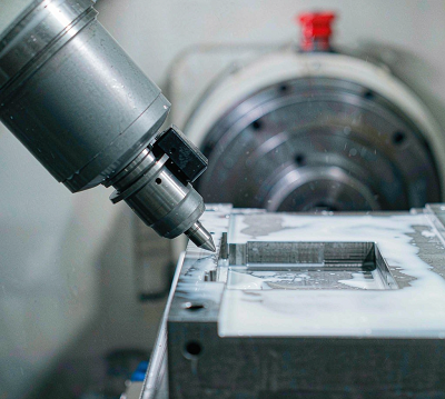
- CNC machining. Cavity and core blocks, plates and electrodes are machined in-house.
- EDM / wire EDM. Ribs, deep slots, sharp corners, texture-ready surfaces and drainage-feature details are finished by EDM.
- Assembly. Shut-offs, parting-line match, slider and lifter travel, cooling connections and ejection movement are fitted and checked.
- T1 trial. The tool runs on an injection press to produce first samples under defined process conditions.
- Correction. Dimensional and cosmetic findings from T1 are corrected in the tool, not compensated for in the process.
- Final approval. Samples are submitted for approval against the agreed criteria; the tool is released for shipment or production.
All six core processes — CNC machining, injection molding, mold making, 3D printing, die casting and sheet metal fabrication — are performed in-house under one ISO 9001:2015 quality system. Across these processes the facility operates 100+ machines.
Quality Control & T1 Mold Trial
A T1 trial is not a formality. It is the point where the design assumptions meet a physical part, and the findings at T1 are what protect the buyer from discovering a problem in month three of production.
- DFM review. Design risks recorded and closed with the buyer before steel is cut.
- Dimensional review. Part geometry checked against the CAD model, including wall thickness at critical sections.
- CNC / EDM inspection. Electrode and cavity features verified against the tool design before assembly.
- Assembly check. Shut-off contact, parting-line match, slider travel, ejection stroke and cooling circuit integrity confirmed.
- T1 trial. Tool run on press under recorded process conditions.
- Sample inspection. First parts measured for dimension, weight, appearance, flash and drainage feature quality.
- Modification. Tool corrections made on the strength of the inspection findings.
- Approval. Final samples and inspection records submitted for approval.
What we look for on planter parts at T1
Planters fail in a predictable set of ways, and each defect points back to a specific decision in the tool or the part design. This is the checklist the trial samples are read against.
| Defect | Where it comes from | Corrected in |
|---|---|---|
| Rim warpage or out-of-round | Uneven wall thickness or cooling imbalance between rim and side wall | Part design and cooling layout |
| Sink marks opposite ribs | Rib too thick relative to the adjacent wall | Part design, then cavity correction |
| Flash at the parting line or around drainage holes | Shut-off wear, insufficient clamp support or a worn core-pin fit | Tool fit and shut-off surfaces |
| Short shot at the end of fill | Venting insufficient at ribs or thin sections, or gate too small | Venting and gate dimension |
| Drag marks on a textured surface | Insufficient draft for the texture depth | Part design and texture specification |
| Ejector pin marks or distortion | Ejection force concentrated on a thin or unsupported area | Ejection layout and pin count |
| Weld line on a visible face | Gate position relative to the drainage features and the flow path | Gate location and, where possible, part design |
| Part sticking on the core | Core under-cooled, or vacuum between part and core on release | Cooling circuit and venting at the core |
What the buyer receives. Trial report with process conditions, sample inspection record, and the list of corrections made after T1. Where a program requires first-article documentation, the report format can be aligned to the buyer's template before the trial.
Balcony Bonsai Mold Project Record
Every completed mold program is documented as a project record with the eight fields below. The record is what makes a quote comparable between suppliers: it states what the tool had to achieve, what made it difficult, and what was verified before release rather than claiming it.
| Project | Balcony bonsai plastic mold program |
|---|---|
| Product | Product reference and part photo — from project record |
| Mold | Tool number, cavity count, runner type — from project record |
| Material | Molding resin and grade — from project record |
| Steel | Cavity / core steel grade and hardness — from project record |
| Key challenge | Drainage feature formation, wall uniformity, rim warpage, release or cycle-time issue — from project record |
| Solution | Tool structure and process change applied — from project record |
| Result | Measured outcome after T1 and correction — from project record |
Data pending. The highlighted fields are populated from the project file after internal confirmation and customer consent. We do not publish project parameters, tolerances or customer references that cannot be traced to a completed job — if a field is not confirmed, it stays empty here and is provided directly during the enquiry.
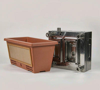
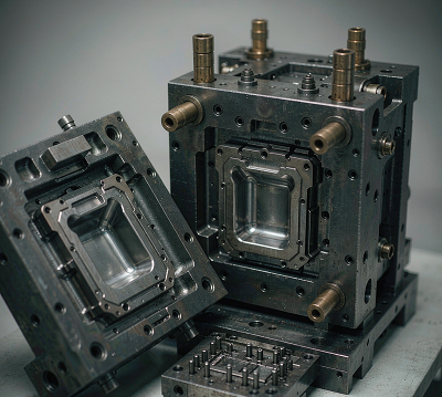
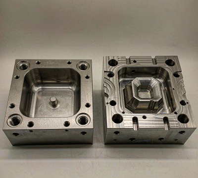
Evidence we supply with a mold program
A mold page is only as credible as its evidence chain. The six items below are the standard proof set for a planter tooling program — each one answers a specific buyer question.
Specifications
The values below are confirmed per project. Where a parameter depends on the part design or the buyer's volume target, it is stated as a selection rather than a fixed number, because a planter program quoted before design review is a program that gets re-quoted.
| Product scope | Balcony planters, bonsai pots, flower pots, nursery pots, decorative planters, garden containers |
|---|---|
| Mold type | Single cavity, multi cavity or family mold |
| Runner system | Cold runner or hot runner, selected on volume and material cost |
| Tool steel | Selected per project: pre-hardened, through-hardened, corrosion-resistant or high-wear tool steel, matched to target life, resin and surface requirement |
| Molding resin | PP, PE / HDPE, ABS, recycled or filled grades, and other engineering resins where the application requires them |
| Cavity count | Defined by annual volume, part size and available press tonnage |
| Drainage features | Formed by shut-off, core pins or side action depending on wall geometry |
| Surface | Polished, matte or textured, specified by surface, pattern and depth |
| Branding | Raised or recessed logo, cavity numbering and date inserts |
| Ejection | Ejector pins, stripper plate, air assist or a combination |
| Design & build | In-house mold design, CNC, EDM / wire EDM, assembly and T1 trial |
| Quality system | ISO 9001:2015 |
| Trial & samples | T1 trial with process record, sample inspection and correction before approval |
| Target mold life | Agreed with the buyer and matched to steel selection and maintenance plan |
| Lead time | Quoted per project after design review; driven by cavity count, steel grade, mechanism complexity and surface finishing |
Applications
Balcony Planters
Trough and railing containers for balcony and apartment gardening, including compact outdoor planting where space and weight matter.
Bonsai Pots
Shallow rigid pots for bonsai cultivation and ornamental plants, with drainage patterns and rim geometry for wiring the root ball.
Decorative Planters
Home and garden decoration, retail planter ranges and landscaping containers where surface finish and color consistency are acceptance criteria.
Nursery Pots
Seedling production, greenhouse growing and commercial nursery supply, designed for stacking and automated de-nesting.
Hanging and wall-mounted planter designs can be reviewed on request; tooling for those geometries involves additional side actions or angled features and is quoted after a feasibility review.
Frequently Asked Questions
What information do you need to quote a balcony or bonsai planter mold?
A 3D CAD model or a dimensioned drawing, target resin, annual production volume, cavity expectation, target mold life, surface finish requirement and destination market. If the design is still open, a sketch with target dimensions and volume is enough to start a feasibility review.
Can a bonsai pot design with drainage holes be produced in a single tool?
Yes, but the drainage feature drives the tool structure. Hole position, count and diameter determine whether the feature can be formed by shut-off between cavity and core, or whether retractable core pins, lifters or side actions are required. This is reviewed during DFM before the steel is cut.
Single cavity or multi cavity for a planter mold?
The decision depends on annual volume, part size, press availability and budget. Single cavity keeps tooling cost and lead time low and suits design validation and low-volume programs. Multi cavity reduces per-part cost and is justified once the annual volume covers the added tooling investment.
Which plastic should be used for balcony planters and bonsai pots?
Resin selection depends on stiffness, impact resistance, outdoor UV exposure, color and cost targets. PP, PE / HDPE and ABS are commonly evaluated for gardening containers, and the final choice is confirmed against product geometry and service conditions.
Do you provide T1 trial samples before the mold ships?
Yes. The tool runs a T1 trial, samples are inspected, and any dimensional or cosmetic findings are corrected before approval. Trial process records and sample inspection records can be provided with the samples.
Can you mold the production parts as well as build the tool?
Yes. Injection molding runs in-house alongside mold making, so a program can be quoted as tooling only, as tooling plus production, or as production on a buyer-owned tool.
What is the minimum order quantity?
For machined and molded parts the sampling minimum starts at 1 piece. For a mold program there is no part quantity — the deliverable is the tool and the approved samples.
How do you handle design changes after the tool has started?
Changes are quoted and scheduled against the current build stage. A change requested before steel cutting is low cost and quick to apply; a change requested after cavity machining requires rework or new electrodes, and is quoted as a separate item with an agreed schedule impact.
Request a Custom Bonsai Pot Mold Quote
Send the six items below and you will receive a tooling proposal with the configuration options and their cost impact, not a single number with no basis.
- 3D CAD or drawing. STEP or IGES preferred; dimensioned 2D drawings are accepted.
- Target resin. Or the property requirements if the resin is not yet chosen.
- Annual volume. This sets cavity count and steel selection.
- Cavity expectation. If you already have a target, state it; if not, we will propose one.
- Target mold life. Which sets the steel grade.
- Surface and appearance requirements. Including where the parting line may and may not be.
Xiamen Goldcattle Plastic & Metal Products Co., Ltd. · Founded in 1998 · Xiamen, China · ISO 9001:2015 · 24-hour response · Customers in 100+ countries