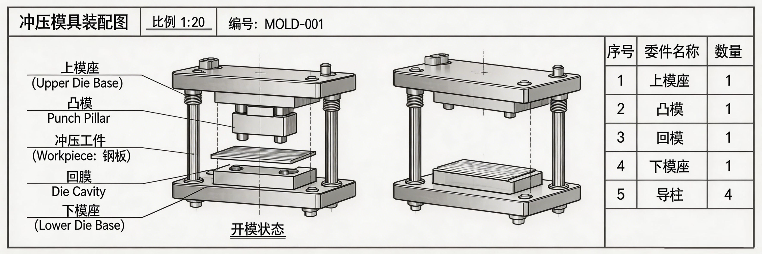
Custom Metal Stamping Die Design and Manufacturing Service

Custom Metal Stamping Die Design & Manufacturing

Progressive, Compound & Precision Tooling Solutions — From Prototype to Mass Production

Progressive • Compound • Single-Stage
SKD11 • DC53 • D2
±0.01mm Tolerance
OEM Drawing-Based

Stamping Die Capability Snapshot

Die Types Progressive • Compound • Single-Stage • Transfer
Tooling Materials SKD11 • DC53 • D2 (A681) • Cr12MoV
Part Thickness Range 0.1 mm – 6.0 mm (Custom per Application)
Dimensional Tolerance Up to ±0.01 mm (Precision Features)
Tool Life 200,000+ Strokes (SKD11); Custom per Project
Prototype Tooling Available — Rapid Soft Tool for Validation
Mass Production Supported — Multi-Cavity Progressive Dies
Industries Served Automotive • Electronics • Medical • Industrial Equipment


Problems We Help Stamping Buyers Solve

Procurement and engineering teams face recurring tooling issues that directly affect production cost, quality and delivery. Each challenge below is addressed through design and material decisions made during the DFM phase.
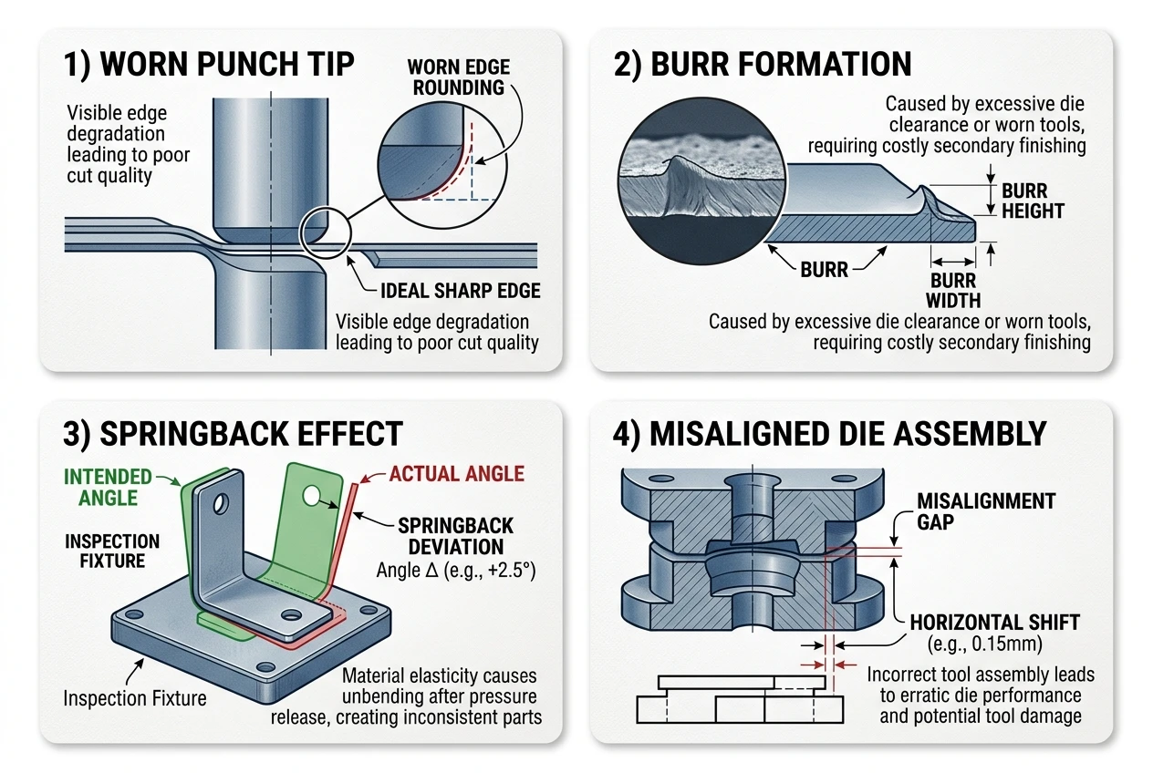
Common stamping die manufacturing challenges punch wear burr springback alignment

Short Tool Life
Problem: Dies require frequent regrinding or replacement, causing unplanned downtime.
Solution: Optimized tool steel grade selection (DC53 for toughness) + proper heat treatment protocol.
Benefit: Reduced maintenance intervals, lower total cost per stroke.
Dimensional Instability
Problem: Stamped part dimensions drift between first article and volume production.
Solution: Precision die design with guided pilot pins, strippers and nest plates.
Benefit: Consistent part geometry from first stroke to end of tool life.
High Per-Part Cost
Problem: Single-operation dies limit throughput; setup time dominates per-part economics.
Solution: Progressive die consolidation — multiple operations in one stroke cycle.
Benefit: 3–5x throughput increase vs line dies; lower unit cost at volume.
Difficult-to-Stamp Geometry
Problem: Complex bends, deep draws or thin-wall features exceed existing die capability.
Solution: DFM analysis + formability simulation before tooling commitment.
Benefit: Fewer tryout iterations, faster TTM, predictable quality.

Which Stamping Die Type Should You Choose?

Die type selection depends on part complexity, volume target, precision requirement and material thickness. The wrong choice increases cost and delays delivery.
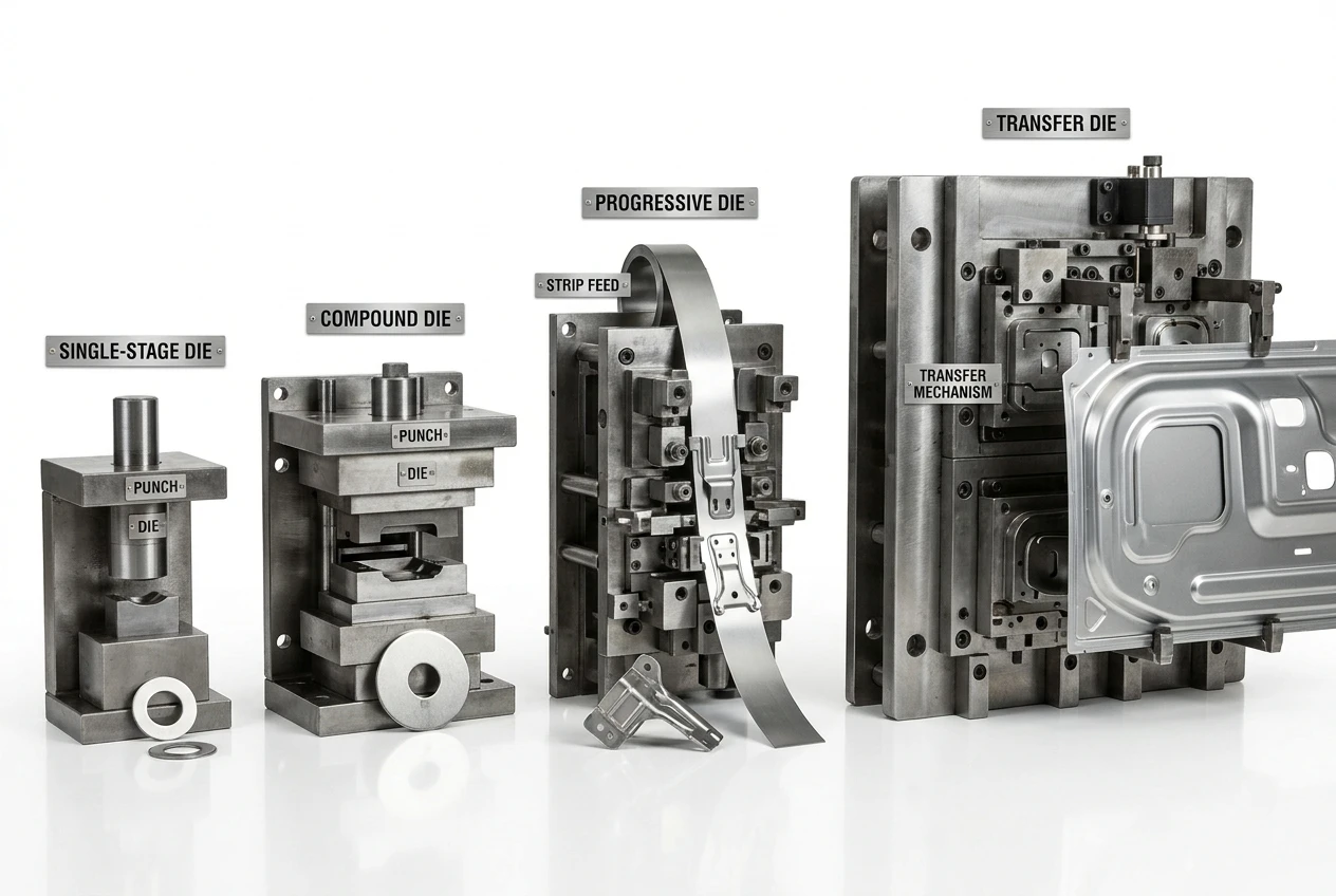
Four stamping die types comparison single-stage compound progressive transfer

Die Type Best For Typical Volume Precision Level Tooling Cost
Single-Stage One operation per stroke. Simple blanks, flat cuts. Low to Medium Standard Lowest
Compound Blanking + piercing in one stroke. High accuracy flat parts. Medium High Moderate
Progressive Multiple stations on strip. Complex parts at high speed. High Volume Very High Higher (amortized at volume)
Transfer Large or deep-draw parts moved between stations. Medium to High High Highest
Selection Guidance
If your annual volume exceeds 100,000 units and the part involves 3+ forming operations, a progressive die delivers the lowest per-part cost despite higher initial tooling investment. For flat blanks under 50,000 units, a single-stage die minimizes upfront commitment. Compound dies excel when hole-to-edge positional accuracy matters (e.g., connector blanks). Transfer dies handle deep draws that progressive strip feeding cannot accommodate.

Tooling Material Selection

Die steel grade directly determines tool longevity, maintenance frequency and per-part cost. Selecting the wrong grade is the most common source of premature die failure.
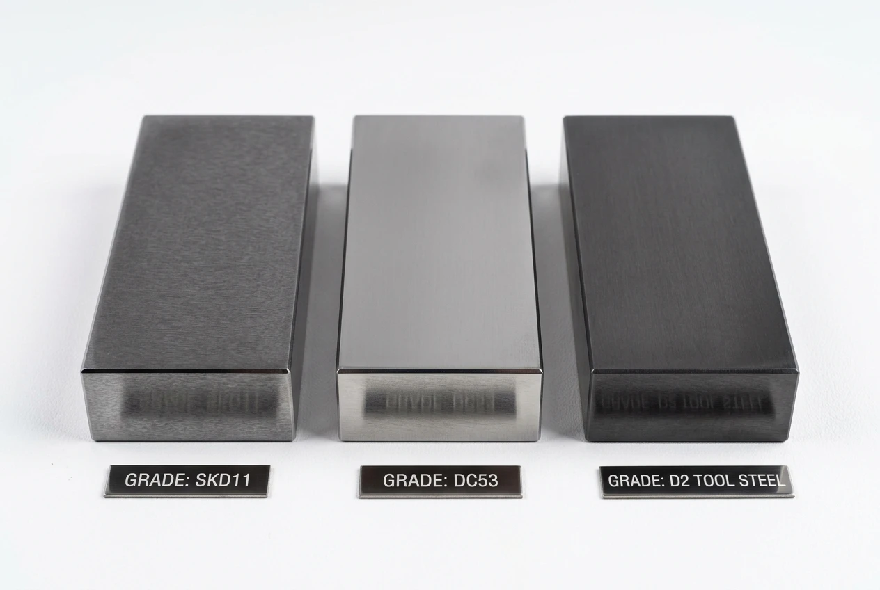
Tool steel material samples SKD11 DC53 D2 comparison for stamping die

Grade Hardness (HRC) Toughness Wear Resistance Best Application
SKD11 58–62 Medium Excellent General blanking, bending. 200k+ stroke tool life. Cost-effective standard grade.
DC53 58–62 Superior Excellent Thin material stamping, fine blanking. Reduced chipping and cracking vs SKD11.
D2 (A681) 58–64 Lower Very High High-wear applications. Long-run progressive dies where dimensional stability over time is critical.
Cr12MoV 55–60 Good Good Economical alternative for medium-volume forming dies. Adequate for bending and light blanking.

Choose SKD11 When
Part thickness ≥ 1.0 mm, annual volume 50k–200k, standard blanking/bending geometry, and cost priority over maximum tool longevity. Most widely available grade with proven track record.
Choose DC53 When
Part thickness ≤ 0.5 mm, fine features prone to punch chipping, high-volume progressive dies requiring minimal regrind intervals, or applications where toughness matters more than raw hardness.

Manufacturing Process

Stamping die design CAD workshop wire EDM manufacturing process

1. DFM & Design
Analyze part geometry, material thickness, bend radius feasibility. Formability simulation (AutoForm/PAM-STAMP) identifies splitting, wrinkling or springback risk before tooling starts.
Annotation: Minimum inner bend radius = 1x material thickness for mild steel.
2. Tooling Fabrication
Wire EDM for punch and die profiles. CNC milling for stripper plates and die sets. Grinding for critical mating surfaces (guide pins, pilot pins).
Annotation: Wire EDM accuracy ±0.003 mm; surface grinding Ra ≤ 0.4 μm on die face.
3. Heat Treatment
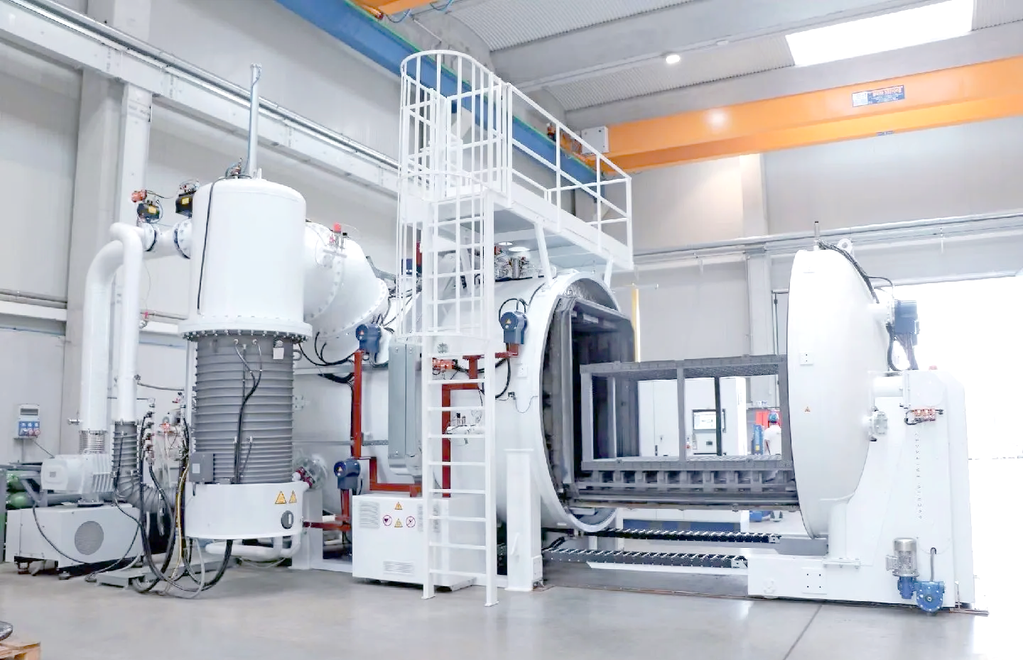
Vacuum quenching + tempering per grade specification. SKD11: 1020°C quench, 200°C temper. DC53: 1030°C quench, dual temper at 520°C + 200°C.
Annotation: DC53 dual temper reduces retained austenite to ≤ 2%, preventing dimensional drift in service.
4. Assembly & Tryout
Die set assembly with guided system. Tryout press running at production speed. First article inspection against drawing tolerance.
Annotation: Clearance = 5–8% of material thickness for blanking; 10–15% for soft metals.
5. Validation & Optimization
Run 500–1000 strokes for progressive dies. Measure burr height, dimensional drift, surface quality. Adjust spring pressure, stripper force and cushion timing if needed.
Annotation: Burr height target ≤ 10% of material thickness (ISO 13715).
6. Production Release
Customer approves first article report. Die shipped with maintenance schedule, spare punch list and stroke counter documentation.
Annotation: SKD11 regrind interval ~50k strokes; DC53 ~80k strokes under equivalent conditions.

Technical Parameters

Parameter Specification
Blanking Tolerance ±0.01 mm (Precision); ±0.05 mm (Standard)
Bend Angle Accuracy ±0.5° (Compensated for Springback)
Burr Height Limit ≤ 10% of Material Thickness (ISO 13715)
Part Thickness Range 0.1 mm – 6.0 mm
Die Clearance 5–8% t (Hard Material); 10–15% t (Soft Material)
Wire EDM Accuracy ±0.003 mm Profile; Ra ≤ 0.8 μm Surface
Heat Treatment Hardness SKD11: HRC 58–62; DC53: HRC 58–62; D2: HRC 58–64
Tool Life (SKD11) 200,000+ Strokes (Medium Carbon Steel Blanking)
Progressive Die Stations Up to 30+ Stations per Die Set
Quality System ISO9001 • First Article Report • CMM Data per Shipment
Process Annotations
Springback Compensation: Bend angle over-form by 2–5° beyond target to offset elastic recovery. Verify with first article measurement and adjust die geometry accordingly.
Clearance Optimization: Excessive clearance increases burr height; insufficient clearance accelerates punch edge wear. Start at 7% of material thickness and fine-tune during tryout.
Stripper Force: Insufficient stripper pressure causes material lift between stations, leading to misfeeds in progressive dies. Calculate based on material thickness × shear area × 10% of shear force.
Heat treatment furnace and hardness testing for stamping die tool steel
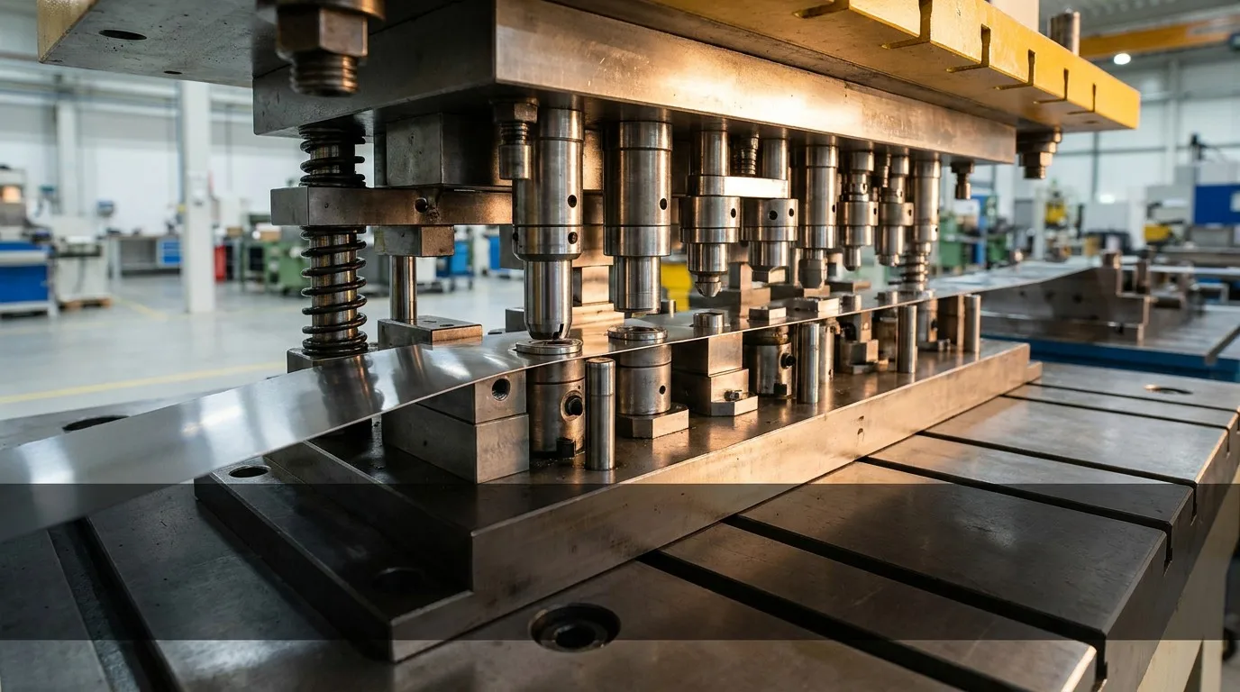
Precision progressive sheet metal stamping die tool manufacturing

Common Challenges in Stamping Die Manufacturing

These are the real issues our engineering team encounters and resolves daily. Addressing them proactively during design prevents costly rework after tryout.

Punch Wear & Chipping
Root Cause: Insufficient punch hardness or inappropriate steel grade for material being cut.
Resolution: Upgrade to DC53 for thin-gauge work (reduces chipping by 40% vs SKD11). TiN or TiCN surface coating extends edge life by 2–3x.
Preventive: Schedule regrind at 80% of predicted stroke count, not after visible wear appears.
Burr Formation
Root Cause: Excessive die clearance or worn punch edge allows material to stretch before fracture.
Resolution: Reduce clearance to 5–7% of thickness. Fine-blanking technique for ≤ 0.05 mm burr height on critical edges.
Preventive: Burr height inspection every 10k strokes. Track trend to predict regrind timing.
Springback
Root Cause: Elastic recovery of formed material after bending force is removed. Worse in high-strength alloys.
Resolution: Over-bend compensation (2–5°). Bottoming technique instead of air bending for consistent angles.
Preventive: Formability simulation before tooling to predict springback magnitude per material grade.
Tool Alignment
Root Cause: Misalignment between upper and lower die halves causes uneven wear, off-center holes and dimensional drift.
Resolution: Precision-ground guide pins + bushings. Parallelism verification on die set before each production run.
Preventive: CMM verification of die assembly alignment during setup. Document guide system condition monthly.

Industry Solutions

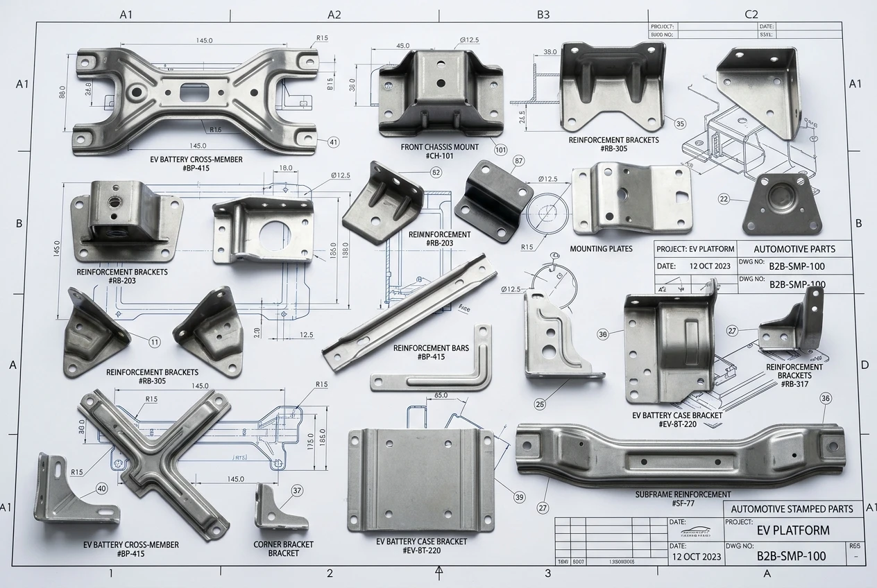
Automotive stamped brackets reinforcement parts EV components

Automotive Stamping Dies
Structural brackets, reinforcement plates, EV battery enclosure components, seat frame sub-assemblies. Progressive dies for high-volume production with multi-station forming + piercing.
Typical: SKD11 die, 1.0–3.0 mm mild steel, 200k+ stroke life

Precision electronics EMI shielding connectors stamping components

Electronics Tooling
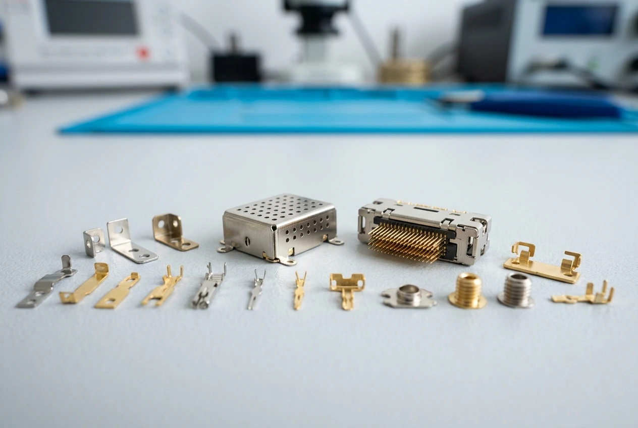
EMI shielding cans, connector blanks with fine pitch pins, precision contacts, lead frames. DC53 preferred for thin-gauge work (0.1–0.5 mm) requiring minimal burr and high positional accuracy.
Typical: DC53 die, 0.1–0.5 mm copper/brass/stainless, ±0.01 mm tolerance

Medical stamping die thin metal instrument components precision

Medical Stamping Dies
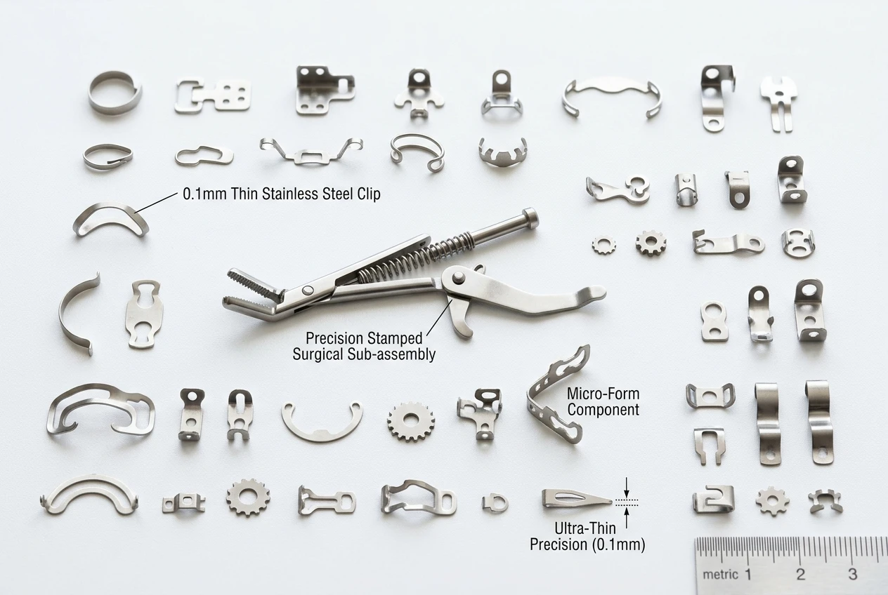
Surgical instrument sub-components, thin-wall clips, implant-formed blanks. D2 tooling for longest possible stroke count in stainless steel blanking. Cleanroom-compatible part handling protocols available.
Typical: D2 die, 0.2–1.0 mm 304/316L stainless, ISO13485 traceability

Industrial equipment stamping die control system machine components

Industrial Equipment
Control panel structural parts, machine housing brackets, actuator components, HVAC hardware. Compound and single-stage dies for medium-volume production with cost-efficient tooling.
Typical: SKD11/Cr12MoV die, 1.0–4.0 mm carbon steel, ±0.05 mm tolerance

Case Studies

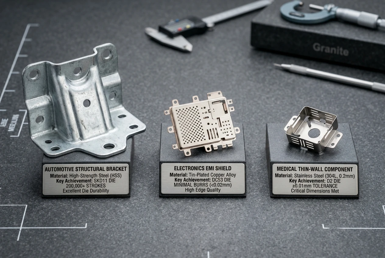
Successful stamping die case study results automotive bracket electronics shield medical component

Automotive Structural Bracket — Progressive Die
Tooling Material SKD11 (HRC 60–62)
Part Material 1.5 mm mild steel (SPCC)
Challenge Customer required 200,000+ annual volume with ±0.05 mm tolerance across 8 formed features, including 3 bends and 5 pierced holes.
Solution 12-station progressive die with guided pilot system. Springback compensated at each bend station. Stripper force optimized for 1.5 mm mild steel feed.
Result First-pass yield 99.2%. Die running at 45 SPM with zero misfeed incidents. 280k strokes achieved before first scheduled regrind — exceeding target by 40%.
Client: European Tier-1 automotive stamping supplier

Electronics EMI Shield — Fine-Blanking Progressive Die
Tooling Material DC53 (HRC 60–62, dual temper)
Part Material 0.3 mm tin-plated copper alloy (C2680)
Challenge Shield walls with 0.3 mm thickness, 15 pierced ventilation holes, 4 bend tabs — burr height must not exceed 0.03 mm for PCB assembly compatibility.
Solution 8-station progressive die with DC53 punch sections. Reduced clearance to 5% of material thickness. TiCN-coated punch tips for extended edge life on thin copper.
Result Burr height consistently ≤ 0.02 mm. Zero punch chipping after 100k strokes (vs SKD11 baseline showing edge micro-cracks at 40k). Production validated by customer PCB assembly team.
Client: North American consumer electronics OEM

Medical Instrument Clip — Compound Die
Tooling Material D2 (HRC 62–64)
Part Material 0.4 mm 304 stainless steel
Challenge Compound blanking + piercing of thin stainless clip with 3 profiled holes. Hole-to-edge positional tolerance ±0.01 mm. Traceability documentation for ISO 13485 compliance.
Solution Compound die with D2 punch and die section. Tight 5% clearance for clean blanking edge. Material traceability logs maintained per production batch.
Result All positional dimensions within ±0.01 mm on first article report. Passed customer’s ISO 13485 supplier validation. Stable production at 30 SPM with dimensional consistency across full batch.
Client: US medical device manufacturer (ISO 13485 certified)

Frequently Asked Questions

What is a progressive stamping die?
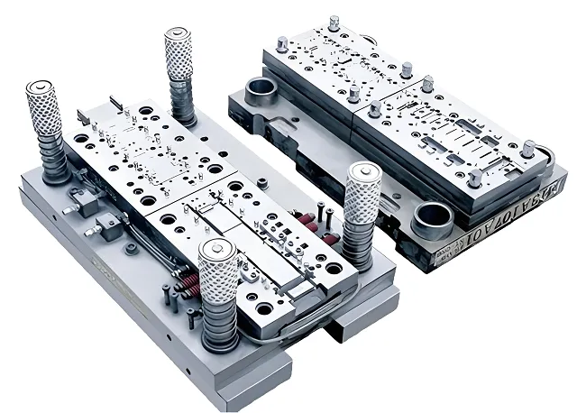
A progressive die performs multiple forming and cutting operations across sequential stations in a single stroke cycle. Sheet metal strip feeds through each station automatically, producing a finished part at every press cycle. This enables high-speed, high-volume production with consistent dimensional output.
How do I choose the right die type?
Match die type to your volume and complexity: single-stage for low-volume simple parts, compound for high-accuracy flat blanks, progressive for high-volume complex multi-feature parts, transfer for large or deep-draw geometry. Our DFM team evaluates your part drawing and recommends the optimal configuration.
What tooling materials are available?
Primary grades: SKD11 (standard wear-resistant, cost-effective), DC53 (superior toughness, reduced chipping), D2/A681 (highest hardness and wear resistance), Cr12MoV (economical for medium-volume). Surface coatings (TiN, TiCN, DLC) available to extend punch edge life by 2–3x.
What tolerance can be achieved?
Precision blanking features reach ±0.01 mm with proper die design and wire EDM fabrication. Standard blanking and bending tolerances are ±0.05 mm. Bend angle accuracy ±0.5° after springback compensation. Hole-to-edge positional accuracy depends on die type — compound dies achieve the tightest relative positioning.
How long does tooling last?
SKD11 dies: 200,000+ strokes for medium carbon steel blanking. DC53: 80k+ strokes before first regrind on thin copper work. D2: longest raw wear resistance but requires careful handling due to lower toughness. Regrinding extends total tool life 3–5x. Scheduled maintenance intervals are documented per die set.
Can prototype tooling be supplied?
Yes. Soft tooling (single-stage or simplified compound) available within 15–20 working days for part validation before committing to full progressive die investment. Prototype tooling cost is typically 30–40% of production die cost, and the design lessons transfer directly to volume tooling.
Do you support OEM drawings?
Full OEM service: tooling designed and fabricated per your part drawings and specifications. NDA-protected manufacturing. Die ownership options available (customer-owned tooling stored and maintained at our facility). We also accept modification requests for existing dies requiring design updates.
What industries do you serve?
Automotive (brackets, EV enclosures, reinforcement), electronics (EMI shields, connectors, lead frames), medical (thin stainless clips, instrument sub-components), industrial equipment (control panels, machine hardware, HVAC). Each industry has specific material, tolerance and traceability requirements addressed in our DFM review.

About Xiamen Goldcattle

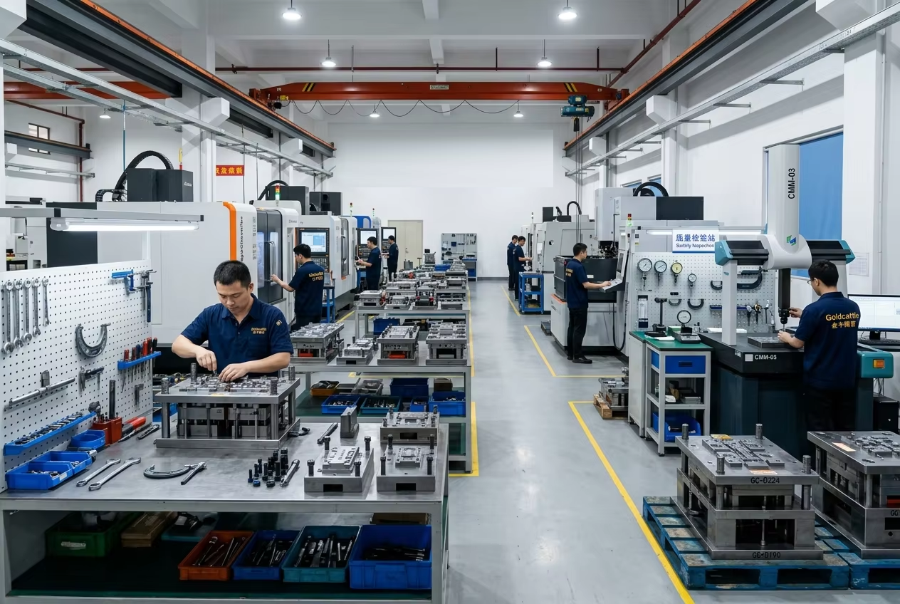
Xiamen Goldcattle Industrial Co., Ltd. provides custom stamping die design, fabrication and tryout services for OEM customers across automotive, electronics, medical and industrial sectors. Our tool room operates wire EDM, CNC grinding, and precision assembly capabilities with full heat treatment and hardness verification in-house.

Established 2008
Export Markets Europe, North America, Asia-Pacific
Quality System ISO9001 Certified
Die Types Progressive • Compound • Single-Stage • Transfer
Tooling Materials SKD11 • DC53 • D2 • Cr12MoV + Surface Coatings
OEM Service Drawing-based • NDA Protected • Customer-Owned Tooling Option
Custom Process: Part drawing submission → DFM analysis & formability simulation → Die concept + station layout → Tooling fabrication (wire EDM, CNC, grinding) → Heat treatment & hardness verification → Assembly & tryout → First article validation → Production release with maintenance schedule.

Manufacturer Snapshot

Company Xiamen Goldcattle Industrial Co., Ltd.
Service Custom Stamping Die Design & Manufacturing
Die Types Progressive • Compound • Single-Stage • Transfer
Tooling Materials SKD11 • DC53 • D2 • Cr12MoV
Tolerance Up to ±0.01 mm (Precision Features)
Tool Life 200,000+ Strokes (SKD11); Extended with Regrind Cycle
Production Prototype Soft Tooling to Mass Production Progressive Dies
Industries Automotive • Electronics • Medical • Industrial Equipment
Quality ISO9001 • First Article Report • CMM Data • Maintenance Schedule

Recommended Reading