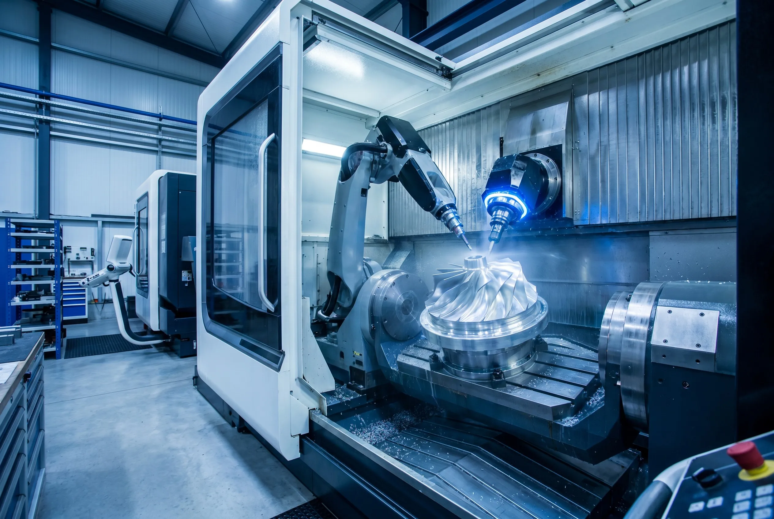
5-Axis CNC Machining Capability Snapshot
| Machining Type | Simultaneous 5-Axis • 3+2 Positional |
| Precision | Up to ±0.005 mm |
| Surface Finish | Ra 0.4–3.2 μm (As-machined to Mirror) |
| Materials | Aluminum • Titanium • Stainless Steel • PEEK • Brass |
| MOQ | 1 Piece (Sample & Prototype) |
| Prototype Lead Time | 3–7 Working Days |
| Inspection | CMM Verification • Dimensional & Visual |
| Industries | Aerospace • Medical • Robotics • Semiconductor • Automotive |
| Quality System | ISO9001:2015 Certified |
Manufacturing Challenges We Help Solve
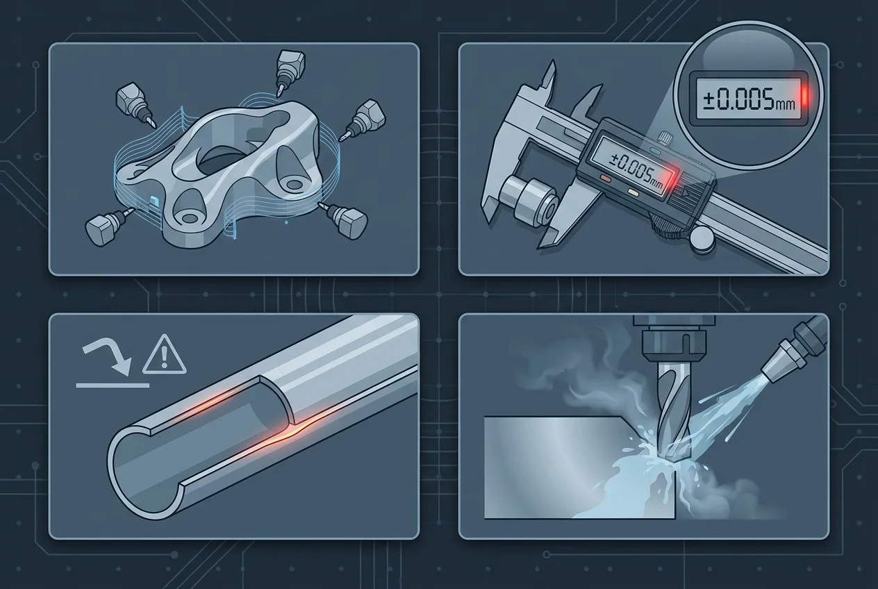
Western procurement teams search for solutions, not machine specifications. Below are the four most common obstacles our 5-axis capability resolves.
Complex Geometry Parts
Problem: Multi-surface structures cannot be completed in one setup on 3-axis equipment. Multiple re-positioning introduces cumulative alignment errors.
Solution: Simultaneous 5-axis tool access eliminates re-positioning. All critical surfaces machined in a single fixture.
Result: Setup error reduced from multi-fixture accumulation to single-reference datum.
Tight Tolerance Requirements
Problem: Assembly interfaces demand ±0.01mm or tighter, but repeated clamping introduces positional drift.
Solution: Single-setup 5-axis processing maintains datum integrity throughout the entire cutting sequence.
Result: ±0.005mm achievable on mating surfaces; assembly fit-up rates improve.
Thin-Wall Deformation
Problem: Wall sections under 1mm deflect under cutting force, causing dimensional drift and chatter marks.
Solution: Optimized dynamic toolpaths with stepped-depth cuts, custom vacuum/fixture support, and controlled ramp-down feed rates.
Result: Thin-wall yield rates increase from 60–70% to above 92%.
Difficult-to-Machine Materials
Problem: Titanium and heat-resistant alloys cause rapid tool wear, excessive heat generation, and poor surface quality.
Solution: High-pressure through-tool coolant (70+ bar), carbide/ceramic tooling, and adaptive feed strategies per material hardness.
Result: Tool life extended 3–5x; surface finish Ra ≤0.8μm on Ti-6Al-4V.
3-Axis vs 5-Axis CNC Machining Comparison
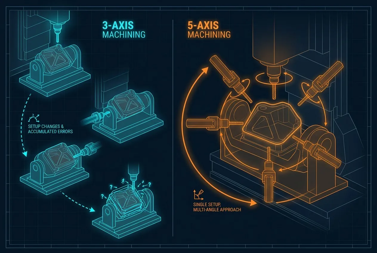
Understanding the capability gap helps procurement teams decide whether 5-axis is justified for their project geometry.
| Feature | 3-Axis | 5-Axis |
|---|---|---|
| Complex Surfaces | Limited — requires multiple setups | Excellent — simultaneous tool approach |
| Setup Count | 2–6 setups typical | Single setup for most geometries |
| Positional Accuracy | ±0.01–0.05mm (accumulates per setup) | ±0.005mm (single datum reference) |
| Production Efficiency | Medium — setup time dominates | High — reduced cycle and lead time |
| Aerospace / Medical Suitability | Limited — prismatic parts only | Ideal — freeform & undercuts |
| Undercut / Backface Access | Not possible | Direct access via B/C axis rotation |
| Tool Length Requirement | Long tools for deep pockets (chatter risk) | Short tools — tilt to optimal angle |
Selection Guidance
3-axis remains cost-effective for flat, prismatic parts with ±0.02mm tolerance. Transition to 5-axis when geometry includes undercuts, curved surfaces, intersecting features at compound angles, or when setup reduction justifies the per-hour premium. For production volumes above 500 units, 5-axis per-part cost often drops below 3-axis due to eliminated setup labor.
Materials for 5-Axis CNC Machining
Selecting the correct alloy directly impacts machinability, surface finish, and project cost. Below is a decision reference based on typical application domains.
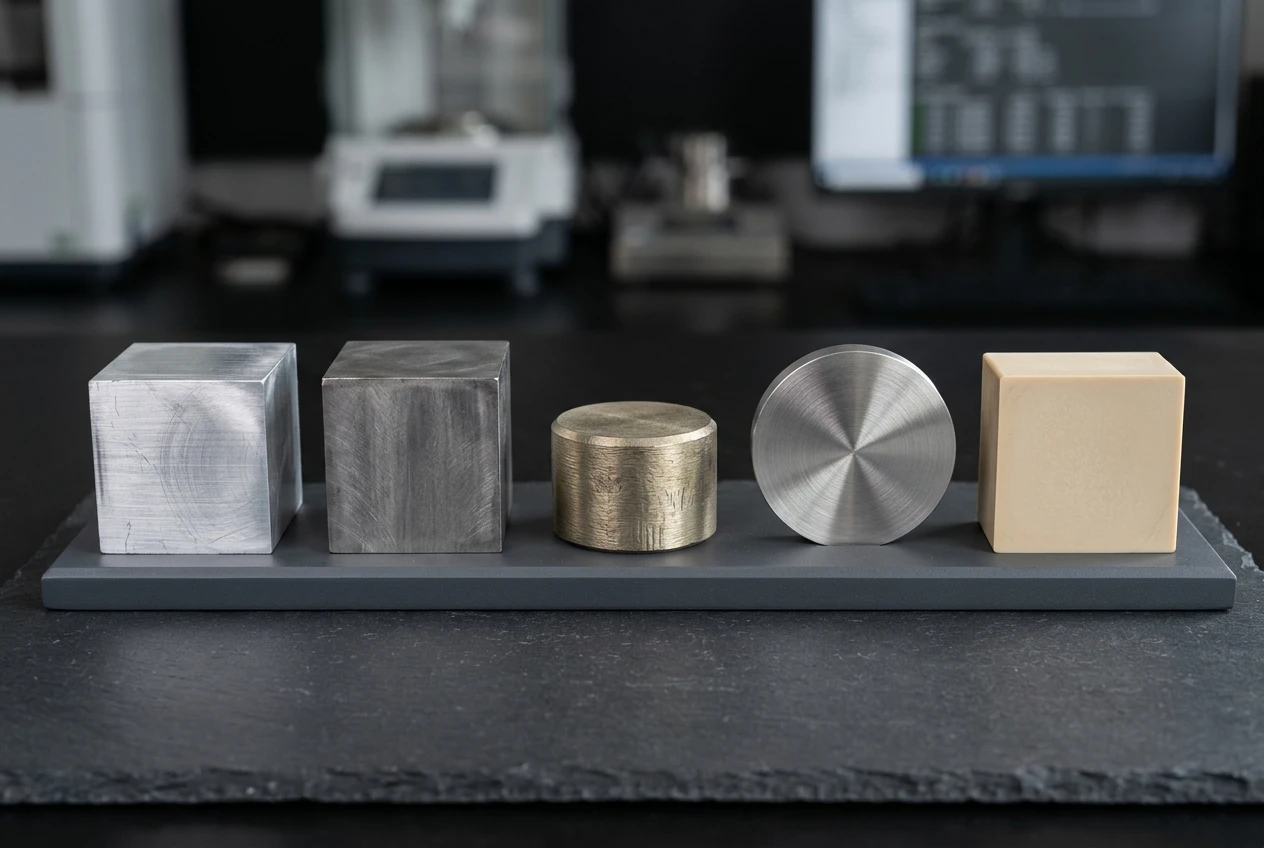
| Material | Key Properties | Typical Application | Machinability Rating |
|---|---|---|---|
| 6061-T6 Aluminum | Good strength, excellent corrosion resistance, weldable | Robotics frames, general structural parts | Excellent |
| 7075-T6 Aluminum | High tensile strength (572 MPa), fatigue-resistant | Aerospace brackets, high-stress members | Good |
| Ti-6Al-4V (Grade 5) | High strength-to-weight, biocompatible (ASTM F136) | Medical implants, aerospace fasteners | Challenging — requires specialized approach |
| 316L Stainless Steel | Corrosion-proof, food/medical grade, hygienic | Food processing, surgical instruments | Moderate — work-hardening risk |
| PEEK Polymer | Chemical-resistant, high temp (250°C), low creep | Semiconductor handling, insulating components | Good — low cutting force |
| Brass C36000 | Free-cutting, excellent thermal conductivity | Valve bodies, electrical connectors | Excellent |
Aluminum vs Titanium for Aerospace
7075-T6 delivers 572 MPa tensile strength at 2.81 g/cm³ density — ideal for structural brackets where weight is a secondary concern. Ti-6Al-4V offers 900+ MPa at 4.43 g/cm³ with superior fatigue life — justified for primary load-bearing members and high-temperature zones.
Decision rule: Use 7075 for brackets, fittings, and secondary structure. Upgrade to Ti-6Al-4V when operating temperature exceeds 150°C or cyclic loading is dominant.
PEEK vs 316L for Semiconductor
316L provides magnetic-shielding, EMI-grounding capability and proven cleanroom compatibility. PEEK eliminates particulate generation, offers inherent chemical resistance to HF and solvents, and operates at 250°C without degradation.
Decision rule: Use 316L when EMI shielding or grounding is required. Use PEEK when electrical insulation, chemical immersion, or low-particle generation is the priority.
5-Axis CNC Manufacturing Process
Each stage includes engineering annotations drawn from production experience with aerospace and medical components.
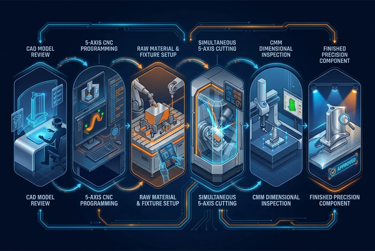
Engineer evaluates geometry against 5-axis access constraints. Wall thickness ≥0.5mm verified; undercuts catalogued for B/C axis angle planning.
Toolpath generation with collision simulation. Rotary axis positions pre-calculated for each operation to maintain optimal cutting angle.
Raw stock sourced with material certification. Custom fixture designed for single-setup gripping; vacuum fixtures for thin-wall components.
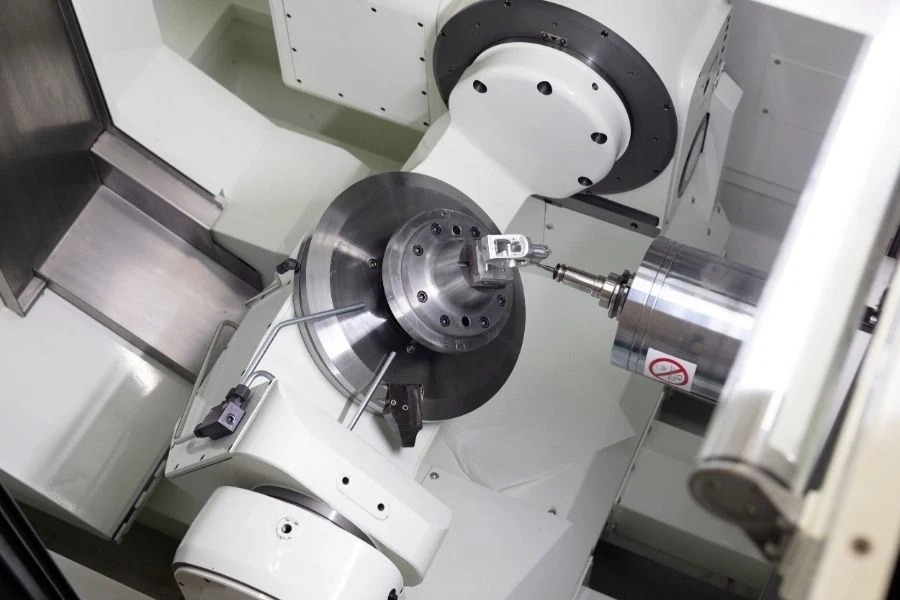
Machine executes programmed toolpaths with real-time axis interpolation. High-pressure coolant (70 bar) activated for titanium and heat-resistant alloys.
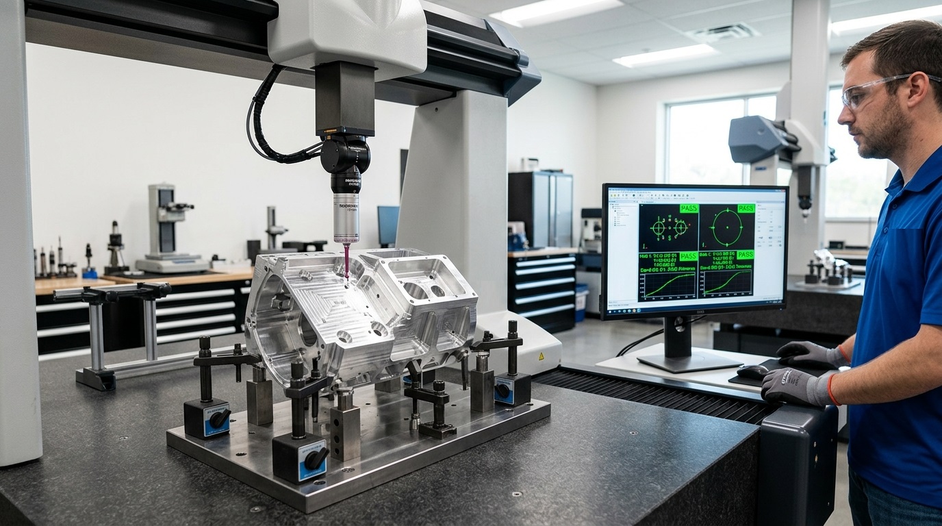
Coordinate Measuring Machine probes all critical dimensions against drawing specifications. GD&T callouts verified: position, profile, orientation.
Anodizing, passivation, electropolishing, or coating applied per specification. Parts cleaned, packaged with CMM reports and material certs.
Technical Parameters
Core process parameters for 5-axis CNC operations, calibrated by material type and application requirements.
| Parameter | Aluminum | Titanium | Stainless Steel | PEEK |
|---|---|---|---|---|
| Spindle Speed | 8,000–24,000 RPM | 2,000–6,000 RPM | 4,000–10,000 RPM | 6,000–15,000 RPM |
| Feed Rate | 3,000–8,000 mm/min | 300–1,200 mm/min | 500–2,000 mm/min | 2,000–6,000 mm/min |
| Depth of Cut (finishing) | 0.1–0.3 mm | 0.05–0.15 mm | 0.1–0.2 mm | 0.2–0.5 mm |
| Minimum Wall Thickness | 0.5 mm | 0.8 mm | 0.5 mm | 1.0 mm |
| Achievable Tolerance | ±0.005 mm | ±0.01 mm | ±0.008 mm | ±0.05 mm |
| Surface Finish (Ra) | 0.4–1.6 μm | 0.8–3.2 μm | 0.4–1.6 μm | 0.8–2.0 μm |
| Coolant Strategy | Flood / mist | High-pressure through-tool (70+ bar) | Flood + peck cycle | Air blast (no liquid) |
| Tool Material | Carbide / HSS | Carbide + TiAlN coating | Carbide / ceramic | Carbide / diamond |
| Max Part Envelope | 600 × 500 × 450 mm | 600 × 500 × 450 mm | 600 × 500 × 450 mm | 600 × 500 × 450 mm |
| File Formats Accepted | STEP / IGES / STL / SolidWorks / AutoCAD / XT | |||
Process Engineering Notes
• Springback compensation: Apply 1–3° over-bend for aluminum bends <90°; 2–5° for titanium. Verified via first-article measurement before production release.
• Thin-wall strategy: Progressive depth reduction (rough at 0.5mm → semi-finish 0.2mm → finish 0.05mm pass) with vacuum fixture support eliminates deflection on walls <1mm.
• Titanium heat management: Through-tool coolant at 70+ bar maintains cutting zone below 200°C. Tool life monitoring: replace carbide end mills at 120-minute intervals for Ti-6Al-4V to prevent edge chipping.
• 5-axis accuracy preservation: Rotary axis calibration checked every 200 hours via ball-bar test. Positional accuracy ≤±0.003° on B/C axes ensures compound-angle feature alignment within specification.
Common Challenges in 5-Axis Machining
Real engineering obstacles encountered in production — and the proven countermeasures we deploy.
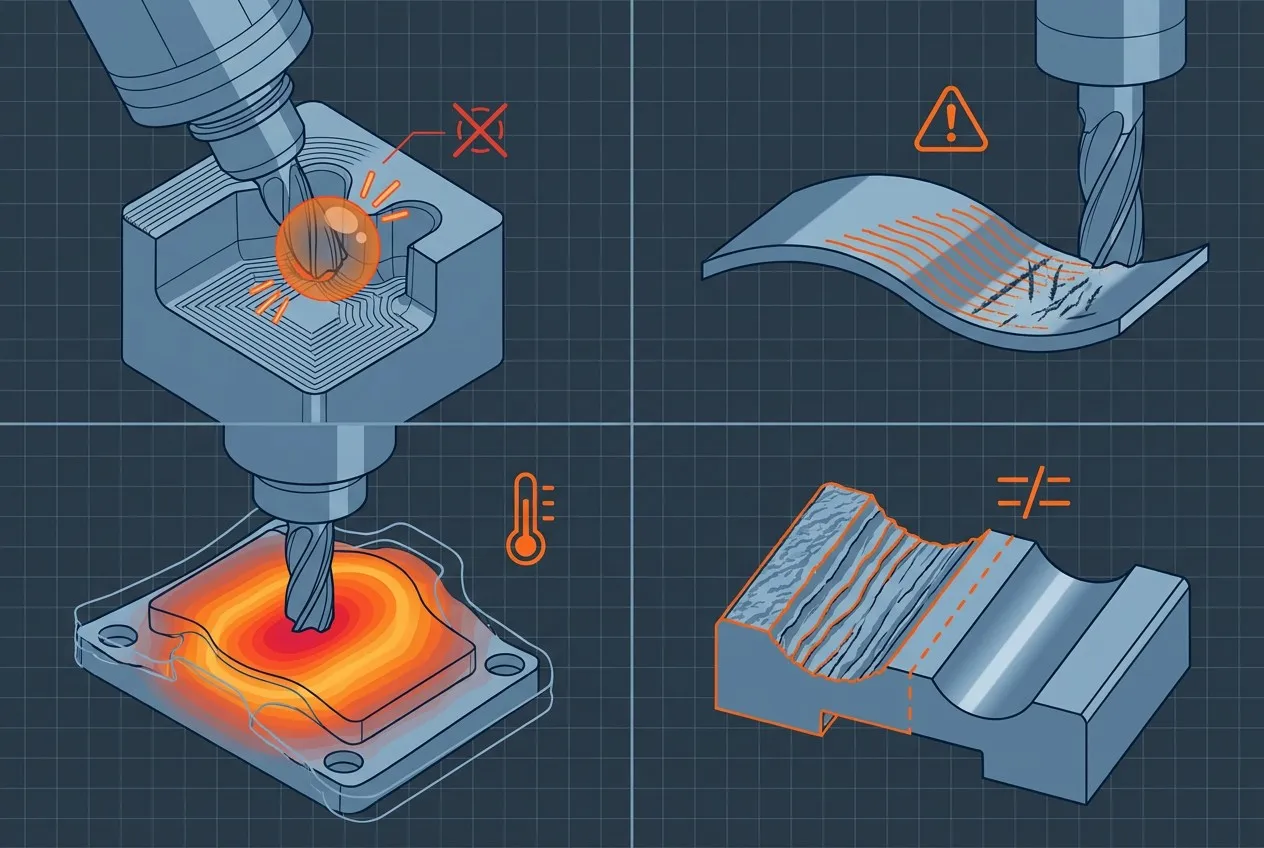
Tool Interference & Collision
In tight geometry zones, the tool holder or shank contacts adjacent surfaces before the cutting edge reaches the target feature. This risk increases with long-reach requirements in deep cavities.
Countermeasure
Full collision simulation in CAM before machining. B/C axis tilt angles calculated per operation to maintain minimum 2mm clearance between tool holder and workpiece. Short-tool strategy prioritized; extended-reach used only when simulation confirms safe envelope.
Thin-Wall Vibration & Chatter
Wall sections below 1mm lack rigidity to resist cutting forces. Resulting chatter leaves periodic surface marks (waviness 0.05–0.2mm) and accelerates tool edge wear through micro-impact loading.
Countermeasure
Dynamic toolpath strategies with trochoidal milling patterns. Stepped-depth approach (0.5→0.2→0.05mm). Vacuum fixture or low-melting-point alloy potting provides structural backing during critical finishing passes.
Thermal Deformation
Titanium and stainless steel retain cutting heat in the workpiece (low thermal conductivity). Localized temperature rise causes dimensional drift of 0.01–0.05mm during prolonged operations, particularly on thin structures.
Countermeasure
High-pressure through-tool coolant (70+ bar) directed at cutting zone. Intermittent cutting strategies for heat-sensitive features. Temperature-monitored environment (±2°C) for critical tolerance work.
Surface Finish Variation
Down-cut surfaces achieve Ra 0.4μm, while up-cut zones may reach Ra 1.6μm on the same component. Variable tool engagement angles in 5-axis paths create inconsistent cutting conditions across freeform surfaces.
Countermeasure
Uniform-direction finishing passes with constant step-over. High-speed finishing strategy (12,000+ RPM) for aluminum. Separate roughing and finishing tools to maintain edge quality on final pass.
Industry-Specific Solutions
Each industry demands distinct material, tolerance, and certification requirements. Our 5-axis capability addresses these directly.
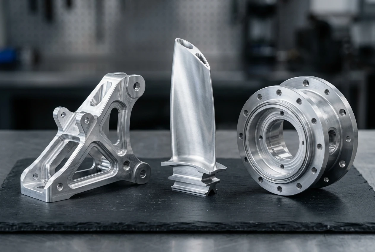
Aerospace Components
Typical Parts: Turbine blade profiles • Structural brackets • Fuselage connectors • Mounting flanges
Key Requirements: ±0.005mm tolerance, multi-surface geometry, weight optimization via internal pocketing
Materials: 7075-T6 • Ti-6Al-4V • Inconel 718
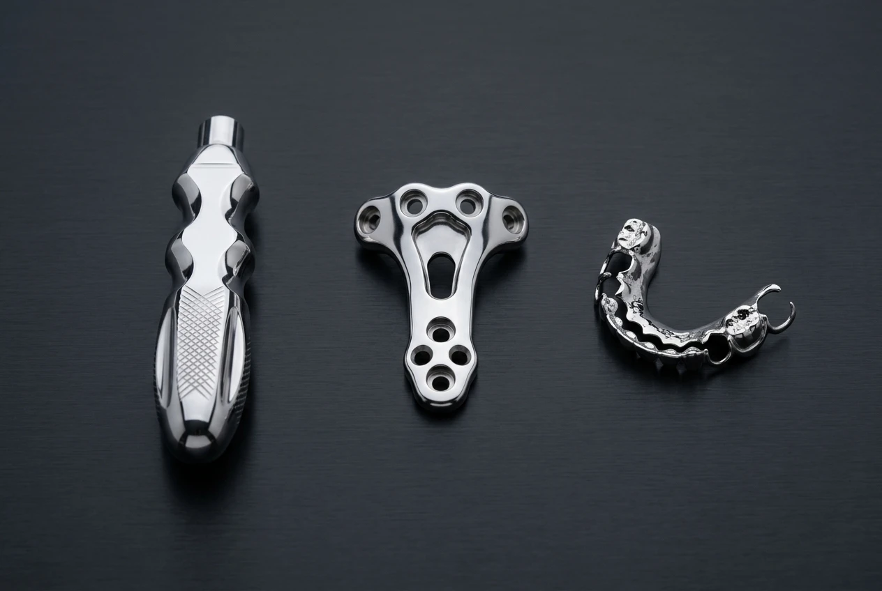
Medical Devices
Typical Parts: Surgical instrument handles • Orthopedic implant fixtures • Dental framework structures • Sensor housings
Key Requirements: Biocompatible grades, Ra ≤0.2μm surface, full material traceability
Materials: Ti-6Al-4V ELI (F136) • 316L • PEEK • CP-Ti Gr.2
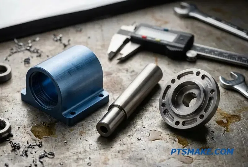
Robotics & Automation
Typical Parts: Joint assemblies • Lightweight structural members • Gear reducer housings • Actuator brackets
Key Requirements: Weight reduction via pocketing, ±0.01mm mating tolerance, structural rigidity
Materials: 6061-T6 • 7075-T6 • Titanium • PEEK
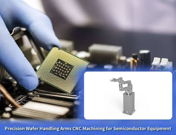
Semiconductor Equipment
Typical Parts: Wafer handling arms • Chamber sealing components • Precision alignment fixtures • EMI shield covers
Key Requirements: Ultra-clean surface, chemical resistance, sub-micron flatness, particle-free processing
Materials: PEEK • 316L electropolished • Aluminum anodized • Quartz
Automotive & EV
Typical Parts: EV battery enclosure brackets • Motor housing components • Suspension link arms • Transmission carriers
Key Requirements: Structural integrity, crash-load pathways, vibration-tested assemblies
Materials: 6061-T6 • 7075-T6 • Cast aluminum post-machined • 4140 steel
Design for Manufacturability Support
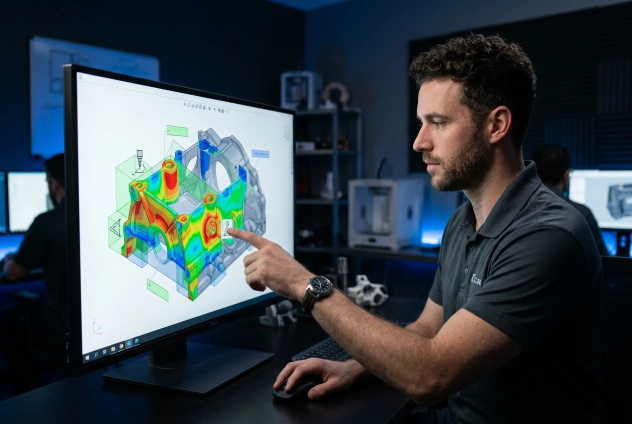
Our engineering team reviews every design before machining. DFM feedback reduces cost, prevents production delays, and optimizes final part quality.
Feature Optimization
Identify features that are difficult or impossible to reach with 5-axis tooling. Suggest alternative geometries that maintain functional intent while improving accessibility. Typical savings: 15–30% cycle time reduction per optimized feature.
Tolerance Review
Flag over-toleranced features where ±0.005mm is specified but functional requirement allows ±0.02mm. Relaxed tolerances reduce inspection cost and increase yield without compromising assembly fit. Every tolerance callout evaluated against actual mating requirement.
Cost Reduction
Material selection alternatives, setup consolidation suggestions, and finish specification alignment. Example: switching from 7075 to 6061 on non-structural members saves 40% raw material cost while maintaining dimensional performance.
Machining Feasibility
Verify wall thickness vs. minimums per material. Check tool access angles for undercuts and backfaces. Validate that internal radii allow standard tool diameters. Surface finish requirements confirmed against achievable Ra per material-process combination.
Case Studies
Real project outcomes demonstrating how 5-axis capability translates into measurable manufacturing improvements.
Structural Bracket — Single-Setup 5-Axis
| Material | 7075-T6 Aluminum |
| Challenge | 14 mating surfaces at compound angles; previously required 4 setups on 3-axis |
| Approach | Simultaneous 5-axis with B-axis tilt for back-face features; single fixture |
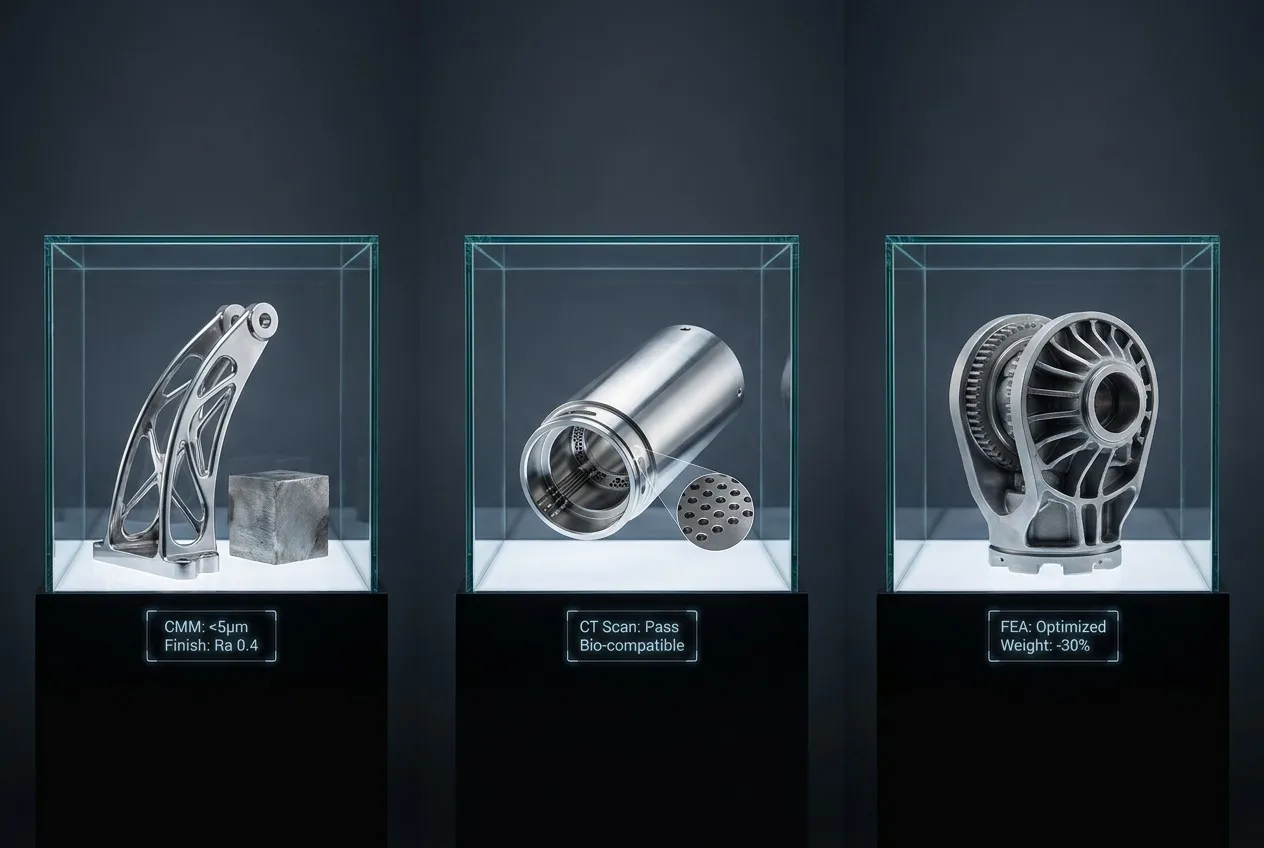
| Result | ±0.005mm achieved on all 14 datum surfaces; lead time reduced 60% |
Previous 3-axis approach accumulated ±0.03mm positional drift across 4 re-positionings. 5-axis single-setup eliminated drift source entirely.
Implant Housing — Micro-Feature Integration
| Material | Ti-6Al-4V ELI (ASTM F136) |
| Challenge | Internal fluid channels (0.8mm dia.) and 6 external mounting interfaces |
| Approach | 5-axis simultaneous for external contours; positional mode for channel drilling |
| Result | Completed in 2 operations (vs. 8 on 3-axis); Ra 0.4μm biocompatible finish |
High-pressure through-tool coolant (70 bar) maintained cutting zone below 200°C, preventing alpha-case formation on titanium surfaces.
Joint Actuator — Weight-Optimized Structure
| Material | 6061-T6 Aluminum |
| Challenge | Internal pocket grid for weight reduction while maintaining 4 bearing bore alignments |
| Approach | 5-axis pocket milling with thin-wall strategy (0.6mm ribs); bore finishing in same setup |
| Result | Weight reduced 22% vs. solid design; all 4 bores ±0.008mm co-axial |
Vacuum fixture held 0.6mm ribs without deflection during finishing passes. Progressive depth strategy prevented chatter on thin-wall sections.
Frequently Asked Questions
What is the advantage of 5-axis CNC machining over 3-axis?
5-axis eliminates multiple re-positioning by accessing all surfaces in a single fixture. This removes accumulated setup error, reduces lead time by 40–60%, and enables undercuts, compound-angle features, and freeform surfaces that 3-axis cannot reach without manual intervention.
What tolerance can 5-axis machining achieve?
On aluminum and steel, ±0.005mm is achievable on mating surfaces. Titanium typically achieves ±0.01mm due to material elasticity. PEEK and polymers reach ±0.05mm. All tolerances verified by CMM inspection with full dimensional reports provided per shipment.
Is 5-axis machining suitable for titanium and difficult alloys?
Yes. 5-axis is particularly advantageous for titanium because the rotary axis tilt allows shorter, stiffer tools — reducing deflection and chatter. Combined with high-pressure through-tool coolant (70+ bar), we achieve Ra 0.8μm surfaces on Ti-6Al-4V with controlled heat management.
What materials can be processed on 5-axis equipment?
Aluminum (6061, 7075, 2024, 5052), Titanium (Grade 5, CP-Ti Gr.2), Stainless Steel (304, 316L, 17-4PH), Brass, PEEK, Delrin, Nylon, Inconel, and copper alloys. Material certification and traceability provided for all orders.
How does 5-axis compare with 3-axis for cost?
Per-hour machine rate is higher for 5-axis. However, single-setup processing eliminates re-positioning labor, reduces total cycle time, and increases yield by removing setup-error scrap. For complex geometries with ≥3 setups on 3-axis, 5-axis total per-part cost is typically 20–35% lower at production volumes.
Can prototypes be supplied before production commitment?
Yes. MOQ starts at 1 piece. Prototypes delivered in 3–7 working days with full CMM dimensional report. First-article approval process ensures production parameters are locked before volume release.
What industries commonly use 5-axis machined components?
Aerospace (structural brackets, turbine profiles, engine mounts), Medical (implant housings, surgical instruments, dental frameworks), Robotics (joint actuators, structural members), Semiconductor (wafer handling, chamber parts), and Automotive/EV (battery enclosures, motor housings, suspension components).
How is dimensional accuracy verified?
CMM (Coordinate Measuring Machine) inspection probes all critical dimensions per drawing specification. GD&T callouts (position, profile, orientation) are verified against tolerance zones. First-article: 100% inspection. Production: 10–20% sampling per lot with all critical features checked every batch.
What file formats do you accept?
STEP, IGES, STL (for reference geometry), SolidWorks (.sldprt/.sldasm), AutoCAD (.dwg/.dxf), Parasolid (.x_t), and PDF dimensioned drawings. Our engineering team reviews all files for DFM optimization before programming begins.
What is the lead time from order to delivery?
Prototype: 3–7 working days. Production (100–500 pcs): 10–15 working days after first-article approval. High-volume (1,000+ pcs): 15–25 working days. Expedited processing available for urgent projects. Shipping via air freight (3–5 days) or sea freight (25–35 days) per customer preference.
About Xiamen Goldcattle
| Founded | 2009 |
| Location | Xiamen, Fujian, China |
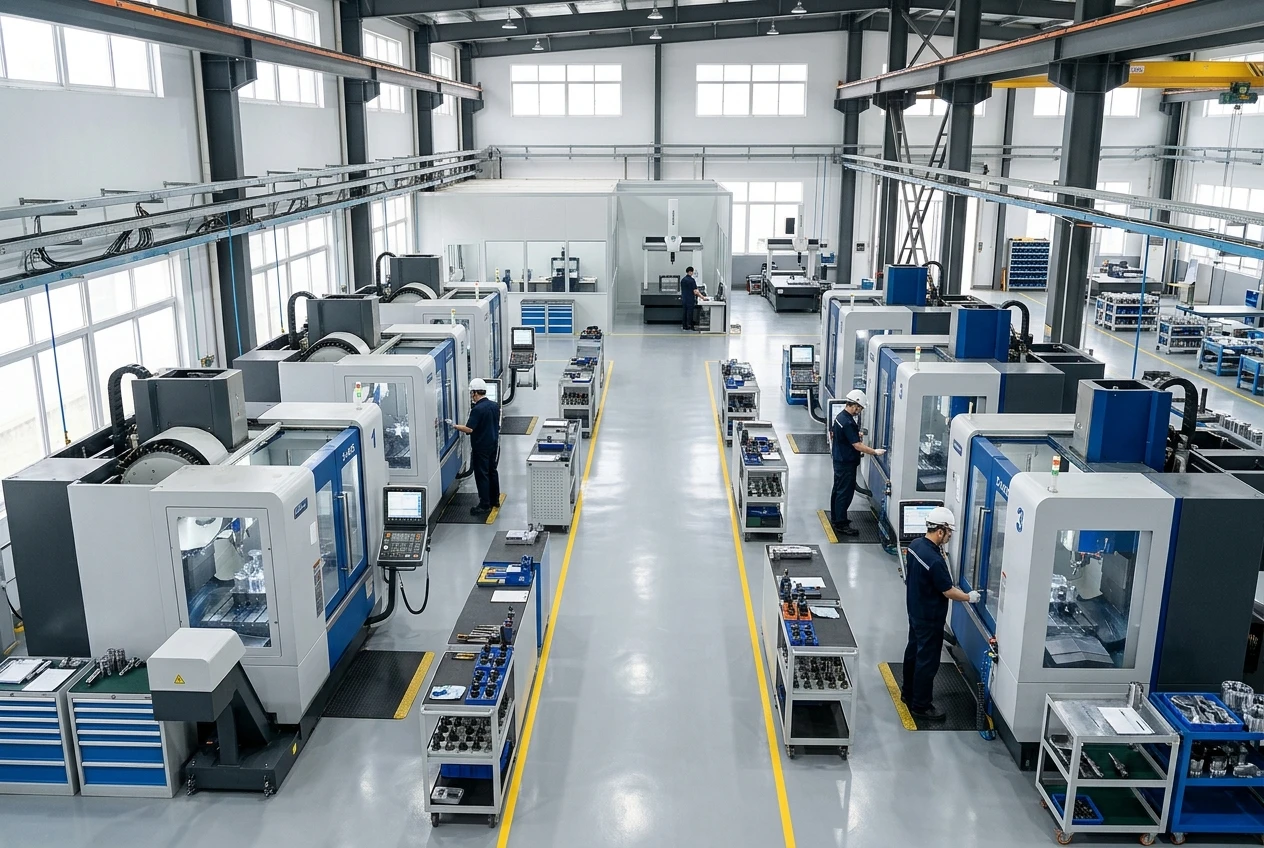
| Workshop Area | 3,500+ m² |
| CNC Machines | 40+ (incl. 5-axis centers) |
| Quality System | ISO9001:2015 |
| Export Markets | North America, Europe, Asia-Pacific |
| Annual Output | 500,000+ precision components |
Xiamen Goldcattle is a precision manufacturing company specializing in custom CNC machined components for aerospace, medical, robotics, and industrial applications worldwide. With 17 years of export experience, we deliver drawing-based manufacturing from prototype through production volumes.
Our 5-axis machining capability enables complex geometry processing that reduces setup count, eliminates accumulated positional error, and shortens delivery timelines. Every component is CMM-inspected against your drawing specification with full dimensional traceability.
Custom Process: CAD Review & DFM Feedback → 5-Axis Programming & Simulation → Material Procurement with Certification → Single-Setup Machining → CMM Verification & First-Article Report → Surface Treatment per Spec → Shipment with Full Documentation
5-Axis CNC Machining Service Summary
| Company | Xiamen Goldcattle (金牛制造) |
| Service | Custom 5-Axis CNC Machining |
| Precision | ±0.005mm (Al/Steel) • ±0.01mm (Titanium) |
| Machining Mode | Simultaneous 5-Axis • 3+2 Positional |
| Materials | 6061/7075 Al • Ti-6Al-4V • 316L SS • PEEK • Brass |
| MOQ | 1 Piece |
| Prototype Lead Time | 3–7 Working Days |
| Surface Finish | Ra 0.4–3.2 μm (Mirror to As-machined) |
| Inspection | CMM Verification • Dimensional Reports per Shipment |
| Industries | Aerospace • Medical • Robotics • Semiconductor • Automotive |
| Quality Certification | ISO9001:2015 |
| DFM Support | Included — Feature Optimization, Tolerance Review, Cost Reduction |
| Website | www.xmgoldcattle.com |