
Wire EDM and Sinker EDM for hardened steels, carbide, titanium, Inconel and other electrically conductive materials requiring intricate features, tight tolerances and controlled surface finishes.
ACCEPTED FILES: STEP · IGES · STL · PDF · DWG · DXF
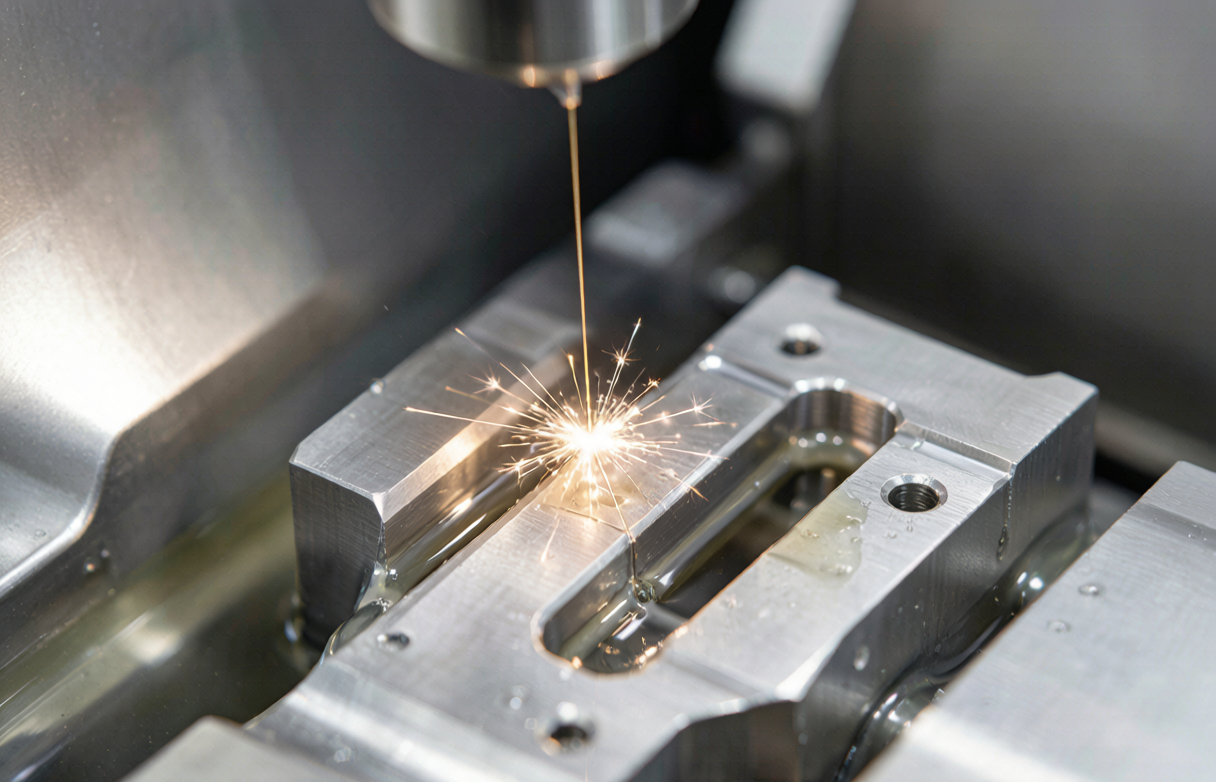 Spark Erosion Machining
EDM Capabilities at a Glance
The values below reflect the capabilities we quote for qualified features under controlled conditions. Exact results depend on part geometry, material, thickness, machine configuration and inspection method.
Important: EDM removes material by controlled electrical discharge between an electrode and a conductive workpiece. It is suitable for electrically conductive materials — non-conductive ceramics and most plastics require other machining methods.
Why Use EDM Instead of Conventional Cutting?
EDM is particularly valuable when hardness, geometry, feature size or cutting-force limitations make conventional machining inefficient or impractical. There is no mechanical cutting force, so thin sections and delicate features remain stable.
Hardened Steel
No cutting force means minimal distortion. Complex details can be finished after heat treatment, which is exactly what hardened molds and dies often require.
Carbide & Hard Alloys
Carbide, Inconel and titanium alloys that are slow or costly to mill can be eroded efficiently by spark discharge.
Deep Narrow Slots
Long, thin cuts and internal profiles are possible without tool deflection or chatter because the electrode or wire does not contact the part mechanically.
Intricate Contours
Complex 2D profiles and 3D cavities can be produced with a single electrode path or shaped electrode, reducing multi-axis setup time.
Sharp Internal Features
Small internal radii and tight corners are achievable where end-mill diameter would be the limiting factor.
Thin Ribs & Delicate Parts
Minimal mechanical loading protects thin walls, narrow ribs and fragile inserts during machining.
Wire EDM vs Sinker EDM
These are two different EDM processes. Choosing the right one depends on whether you need a through profile or a blind cavity, and on the geometry of the feature.
| Feature | Wire EDM | Sinker EDM |
|---|---|---|
| Cutting Principle | Continuous wire electrode | Shaped electrode |
| Main Use | Through profiles, slots, inserts | Blind cavities, 3D shapes, deep ribs |
| Workpiece | Electrically conductive materials | Electrically conductive materials |
| Through-Cut | Excellent | Not the primary use |
| Blind Cavity | Limited | Excellent |
| Complex Internal Profile | Excellent | Excellent |
| Mold Cavities | Some applications | Excellent |
| Electrode Required | Wire spool | Custom copper or graphite electrode |
| Typical Application | Dies, inserts, precision profiles | Mold cavities, ribs, deep pockets |
Wire EDM Services
Wire EDM uses a continuously fed electrically conductive wire as the electrode to cut precise profiles through conductive workpieces.
Best For
- Punch and die components
- Mold inserts
- Precision slots and keyways
- Thin profiles and internal contours
- Hardened steel components
- Carbide profiles
- Complex 2D and contoured features
- Tapered profiles (4-axis where supported)
Wire EDM Features We Machine
Engineers usually ask whether a specific geometry can be wire-cut. The list below covers the feature families we handle most often.
Through Profiles
External and internal contours cut straight through the workpiece.
Internal Cutouts
Closed profiles and windows requiring a pre-drilled start hole.
Thin Slots & Keyways
Long, narrow slots with controlled width and straightness.
Precision Inserts
Hardened inserts for molds, dies and stamping tools.
Punches & Dies
Matched punch and die sets finished after heat treatment.
Carbide Components
Profiles in tungsten carbide and other hard conductive materials.
Tapered Profiles
Top-and-bottom profile control when 4-axis taper cutting is available.
Small Internal Radii
Tight corners limited by wire size and spark gap.
Wire EDM Design Considerations
A design that is easy to wire-cut reduces setup time, wire consumption and cost. These are the practical questions our engineers review during DFM.
Start Hole
Most internal profiles need a pre-drilled start hole so the wire can thread through. If it is not present, EDM hole drilling or conventional drilling may be needed first.
Wire Access
The design must provide a practical entry path. Tangled internal contours or enclosed cavities cannot be wire-cut without access.
Part Thickness
Thicker parts reduce flushing efficiency and can affect corner accuracy and surface finish.
Corner Radius
Internal corners are limited by wire radius plus spark gap. Sharp 90° internal corners are not possible.
Taper Requirement
Specify top and bottom profiles separately if taper or draft is required.
Fixturing & Slug Removal
How the part is held and how the cut-out slug is removed must be planned before cutting starts.
Sinker EDM Services
Sinker EDM uses a shaped electrode to create cavities and complex three-dimensional features in conductive workpieces.
Best For
- Deep ribs and thin walls
- Blind cavities and pockets
- Complex mold details
- Hardened inserts
- Sharp internal geometry
- Small 3D cavity features
- Features where a shaped electrode is more efficient than a milling tool
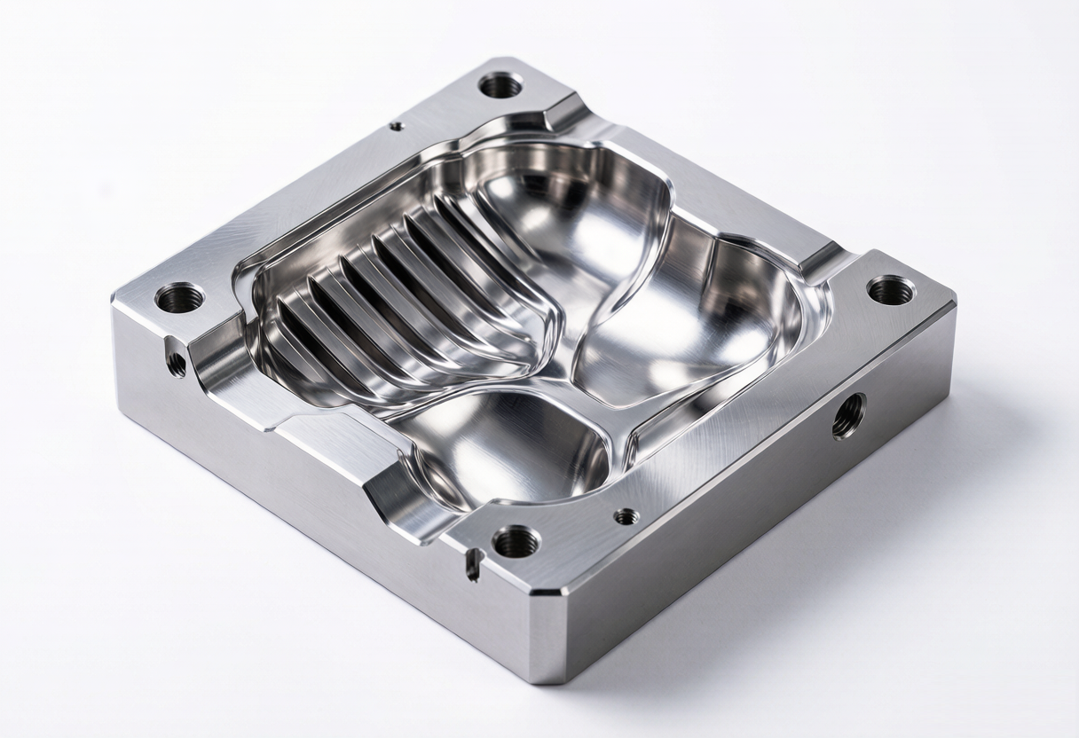
Sinker EDM Electrode Design
The electrode is the key difference between Sinker and Wire EDM. Its material, geometry and wear compensation strategy determine cavity accuracy and cost.
Copper Electrodes
Good detail reproduction and low wear for fine finishing. Often used for precision cavities and small features.
Graphite Electrodes
High material-removal rate and excellent for larger cavities or roughing passes. Easier to machine into complex shapes.
Wear Compensation
Electrode wear is compensated by using multiple electrodes or by adjusting the burn depth between rough and finish passes.
EDM Materials and Hardness
EDM is suitable for electrically conductive materials, including hardened steels and many conductive alloys. Non-conductive ceramics and plastics generally require other machining methods.
Materials We Work With
- Hardened tool steel — H13, S136, SKD11 / D2 and other supported grades
- Carbide — punches, wear parts, tooling components
- Nickel-based alloys — Inconel
- Titanium — Ti-6Al-4V and similar grades
- Other conductive alloys — reviewed per project
Material rule: EDM requires an electrically conductive workpiece. Non-conductive ceramics, most plastics and insulating coatings cannot be machined by conventional EDM.
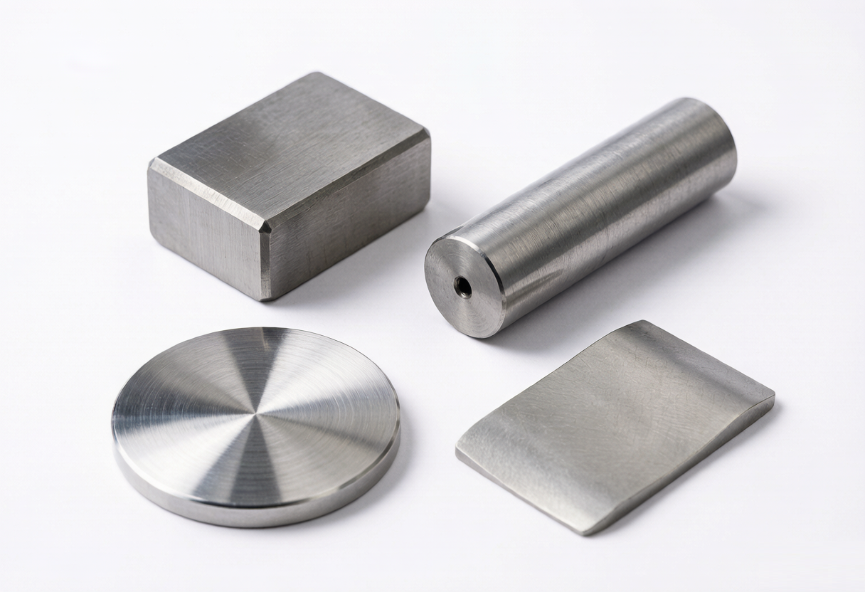
EDM for Hardened Materials
One of the main reasons buyers choose EDM is that complex details can be finished after heat treatment. This preserves hardness where it matters.
EDM Tolerance and Precision
Tolerance is not a single number. It depends on the feature, material thickness, machine condition, wire or electrode selection, and how the part is measured.
Profile Tolerance
How closely the cut profile matches the 2D drawing.
Hole / Slot Size
Dimensional accuracy of internal features after kerf compensation.
Position & Concentricity
Feature location relative to datums and other part geometry.
Straightness & Taper
Control of wall straightness and top-to-bottom profile variation.
Corner Radius
Smallest achievable internal radius, limited by wire or electrode geometry.
Surface Finish
Ra value after rough, semi-finish or finish passes.
Qualified Features
Tighter tolerances reserved for features that geometry, setup and inspection can support.
Inspection Method
CMM, optical comparator or roughness tester depending on the dimension.
Typical capability: ±0.005 mm for common features; ±0.003 mm achievable on qualified features under controlled conditions. We quote each tolerance requirement after reviewing the drawing.
EDM Surface Finish
Multiple EDM passes can be used when tighter size and surface-finish requirements are needed. Each pass removes less material and leaves a finer finish.
| Pass Type | Surface Finish | Typical Use |
|---|---|---|
| Rough Cut | Ra 1.6–3.2 μm | Fast material removal, general profiles |
| Semi-Finish | Ra 0.8–1.6 μm | Intermediate accuracy before final pass |
| Finish Cut | Ra 0.4–0.8 μm | Tight tolerance and better surface quality |
| Fine Finish | Ra 0.2–0.4 μm | Qualified features and cosmetic cavity surfaces |
Important: Surface finish depends on machine, material, discharge parameters, number of finishing passes and part thickness. The values above are typical ranges, not guarantees for every geometry.
Wire Diameter, Kerf and Feature Size
Wire diameter and electrical discharge gap influence the smallest practical feature size, internal corner radius and cutting strategy. Wire diameter is not the same as kerf.
Wire Diameter
Common diameters range from 0.15 mm to 0.30 mm. Thinner wire allows smaller corner radii and finer features but cuts more slowly.
Spark Gap
The discharge gap around the wire adds to the effective cut width. It is controlled by voltage, current, dielectric flushing and workpiece material.
Effective Kerf
Effective kerf = wire diameter + spark gap on both sides. This value is used to offset the wire path so the final dimension is correct.
Feature Accuracy
Smaller features and thinner sections require slower cutting, finer wire and better flushing to hold tolerance.
Engineering note: Do not confuse wire diameter with kerf. A 0.15 mm wire does not produce a 0.15 mm slot. The spark gap must be added, and the actual kerf is larger.
EDM Design & DFM Guidelines
Most buyers are not asking "Can you EDM?" They are asking "Can my design actually be EDM machined?" These are the practical checks our engineers use during DFM review.
Wire EDM Checklist
- Is there a start hole for internal profiles?
- Can the wire access every profile?
- What is the part thickness?
- What internal corner radius is acceptable?
- Is taper required top-to-bottom?
- How will the slug be removed and the part fixtured?
Sinker EDM Checklist
- Can the electrode enter the cavity?
- What is the cavity depth-to-width ratio?
- Is dielectric flushing access adequate?
- How much electrode wear is expected?
- Are sharp internal corners realistic?
- Should the electrode be split into sections?
Can This Feature Be CNC Milled or Should It Be EDM?
EDM and CNC are complementary, not competing. The table below helps identify which process is the more practical first choice.
| Feature / Situation | Conventional CNC | EDM |
|---|---|---|
| Hardened Steel | Difficult and slow | Strong |
| Carbide | Limited | Strong |
| Deep Narrow Rib | Challenging | Strong |
| Sharp Internal Corner | Radius limited by cutter | Small radius possible |
| Blind Cavity | Strong with end mills | Sinker EDM |
| Through Profile | Strong | Wire EDM |
| Very Soft Aluminum | Usually better | EDM usually unnecessary |
| Complex Freeform Surface | CNC often better | Depends on geometry |
Integrated CNC + EDM Machining
When a part needs both material removal and precision finishing, combining CNC and EDM in one workflow reduces handling, lead time and accountability gaps.
Mold Insert Example
CNC rough milling → heat treatment → Wire EDM profile → Sinker EDM detail → grinding → CMM inspection. One workflow, one supplier.
Punch Example
CNC machining → heat treatment → Wire EDM profile → surface finish control → final inspection. Hard, precise profile finished after hardening.
Advantage: Because Goldcattle runs CNC, EDM, heat-treatment coordination and finishing under one project path, we can choose the most efficient process sequence instead of forcing every feature into a single machine type.
Our EDM Machining Process
Each EDM job follows a structured process path so that process selection, electrode or wire strategy, machining and inspection are documented before the first spark.
For Sinker EDM, the flow expands to include electrode design → electrode manufacturing → EDM sinking before rough and finish passes begin.
EDM Quality Control and Inspection
EDM parts are inspected differently depending on whether they are wire-cut profiles or sinker-machined cavities. We match the inspection method to the feature.
Wire EDM Inspection
- Profile and contour accuracy
- Slot / hole dimensions
- Taper and corner geometry
- Surface finish (roughness tester)
Sinker EDM Inspection
- Cavity dimensions and depth
- Electrode wear compensation
- Corner radius and surface quality
- Position relative to datums
Material Verification
- Rockwell hardness test
- Material certificate review
- Heat treatment certificate when required
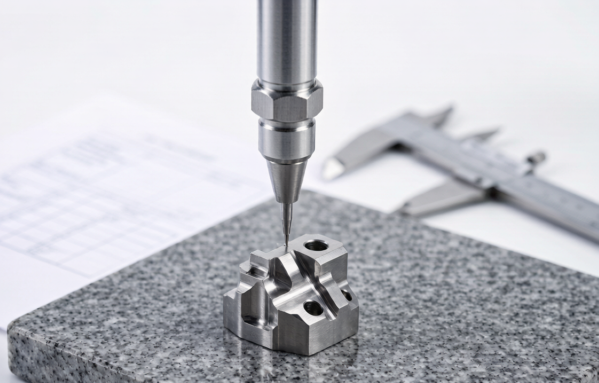
EDM Workpiece Size and Feature Capabilities
Machine travel, workpiece weight and electrode size define what we can handle. The table below is a starting point; final feasibility is confirmed after drawing review.
| Parameter | Typical Capability |
|---|---|
| Maximum Workpiece Size | Project dependent — confirm with drawing |
| Maximum Thickness | Project dependent — depends on wire access / flushing |
| Maximum Workpiece Weight | Project dependent |
| Smallest Practical Feature | ~0.10–0.20 mm |
| Wire Diameter | 0.15–0.30 mm |
| Taper Angle | Project dependent (4-axis where supported) |
| Maximum Electrode Size | Project dependent |
Send the drawing: Because EDM is sensitive to geometry, material and setup, the fastest way to confirm capability is to send the CAD file and let our engineers review it.
EDM Machining Applications
The strongest applications are those where hardness, geometry complexity or cutting-force limits make conventional machining impractical.
Mold & Die Components
Core inserts, cavity inserts, punches and dies finished after hardening.
Precision Stamping Dies
Cutting inserts, punches and die plates requiring matched profiles.
Medical Components
Precision conductive parts where feature accuracy and surface finish matter. (Depth depends on project requirements and certifications.)
Aerospace
Hard alloy components and precision conductive parts for tooling and fixtures.
Electronics Tooling
Connector tooling and precision components for production fixtures.
Carbide Tooling
Wear components, inserts and tooling parts in tungsten carbide.
EDM Case Studies
Each case below highlights why EDM was the right choice and how the process sequence solved a machining bottleneck.
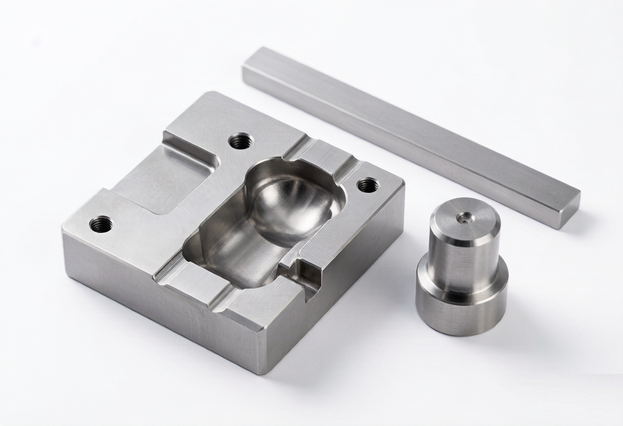
Hardened S136 Mold Insert
Challenge: The cavity profile was located in hardened S136 after heat treatment. Conventional milling would require long, small-diameter tools and risked chatter and size drift.
Solution: CNC roughing before heat treatment, followed by Wire EDM to finish the cavity profile in the hardened state.
Result: Stable profile geometry and consistent cavity size without tool deflection. Dimensional inspection performed by CMM.
H13 Mold Cavity with Deep Ribs
Challenge: Deep, narrow ribs in a hardened H13 cavity. Long end mills would be fragile and prone to vibration.
Solution: Sinker EDM with a custom electrode. Rough and finish passes controlled rib width, corner radius and surface finish.
Result: Consistent rib geometry and surface finish across the cavity. Subsequent polishing time reduced.
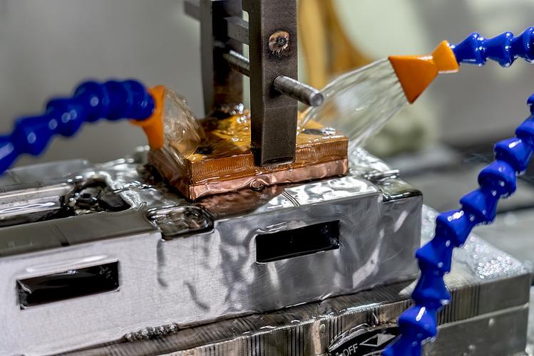
Carbide Punch Profile
Challenge: A complex profile in tungsten carbide, a material that is slow to grind and difficult to mill economically.
Solution: Wire EDM with a finishing pass to control profile tolerance and edge condition.
Result: Accurate carbide profile without grinding the entire contour. Optical inspection confirmed edge geometry.
What Affects EDM Machining Cost?
EDM cost is driven by more than machine time. Setup, electrode or wire strategy, number of finishing passes and geometry complexity all affect the final quote.
Material Factors
Material hardness, type and thickness affect cutting speed, wire wear and electrode strategy.
Geometry Factors
Cutting length, number of features, corner radius requirements and cavity depth.
Process Factors
Number of EDM passes, surface finish target, tolerance grade and inspection requirements.
| Cost Factor | Wire EDM | Sinker EDM |
|---|---|---|
| Electrode | Continuous wire | Custom copper / graphite electrode |
| Electrode Cost | Wire consumption only | Additional electrode manufacturing cost |
| Setup | Relatively straightforward | Electrode planning and alignment |
| Blind Cavity | Not ideal | Excellent |
| Through Profile | Excellent | Less suitable |
| Multiple Cavities | Depends on geometry | Electrode strategy important |
EDM Machining Lead Time
Lead time depends on material availability, electrode manufacturing, part thickness, required finish and tolerance. The table below shows a typical breakdown.
| Project Stage | Typical Time |
|---|---|
| DFM / Process Review | 1–2 working days |
| CAD Programming | 1–2 working days |
| Electrode Manufacturing (Sinker) | 2–4 working days |
| EDM Machining | Project dependent |
| Finish Passes | Project dependent |
| Inspection & Report | 1–2 working days |
Prototype to production: First article samples may take longer because process parameters are proven. Repeat lots are typically shorter once the program and electrode are validated.
What Do We Need for an EDM Quote?
The more engineering context you provide, the faster we can recommend the right EDM route and quote accurately.
Part Data
3D CAD (STEP / IGES / STL), 2D drawing (PDF / DWG / DXF), part name and revision.
Material & Hardness
Material grade, heat treatment condition and hardness if already known.
Feature Requirements
Critical tolerances, surface finish, minimum feature size, corner radius and taper requirements.
Process Preference
Wire EDM, Sinker EDM, or "Not Sure" — process selection is part of our engineering service.
Quantity
Prototype, pilot or production volume, and whether electrodes need to be retained for repeats.
Inspection & Documentation
CMM report, hardness report, material certificate or FAI requirements.
Frequently Asked Questions
What is EDM machining?
What is the difference between Wire EDM and Sinker EDM?
When should I use Wire EDM instead of CNC milling?
Can EDM machine hardened steel?
Can EDM machine carbide?
Can EDM machine Inconel or titanium?
What tolerance can Wire EDM achieve?
What surface finish can EDM achieve?
What is wire EDM kerf?
Can Wire EDM cut blind cavities?
What is a Sinker EDM electrode?
Can EDM machine small internal corners?
Can EDM machine after heat treatment?
Can CNC and EDM be used on the same part?
What information do you need for an EDM quote?
Request an EDM Machining Quote
Upload your CAD, drawing and material details. Our engineers will recommend Wire EDM, Sinker EDM or an integrated CNC + EDM process and return a project-specific quote.
ACCEPTED FILES: STEP · IGES · STL · PDF · DWG · DXF