
Insert Molding for Metal & Plastic Integrated Components
Mold metal or plastic inserts directly into injection molded parts to create stronger interfaces, integrated threads, bushings, terminals and structural reinforcement while reducing secondary assembly.
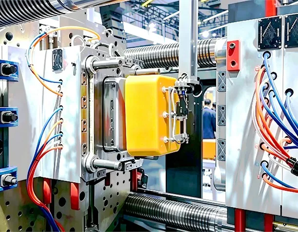
When Should You Use Insert Molding?
Insert molding is a process decision, not a default. These five situations are where it earns its place.
You Need Integrated Threads
Threaded nuts, bushings and studs for parts that need repeated assembly, thread strength or a wear-resistant thread interface.
Plastic Alone Cannot Provide the Strength
A metal insert carries the load where the assembly interface needs greater mechanical strength, wear resistance or dimensional stability than the surrounding plastic can provide.
You Want to Reduce Secondary Assembly
Separate parts, installation, alignment and fastening can be replaced by a molded-in insert. Insert molding can reduce or eliminate selected secondary assembly steps — not every step in every case.
The Insert Must Be Precisely Located
Electrical terminals, pins, bushings, threaded components and mounting features where position is defined by the mold, not by a manual assembly step.
You Need Localized Reinforcement
Metal reinforcement at mounting points, fastening points and load-bearing interfaces inside a plastic structural body.
How Insert Molding Works
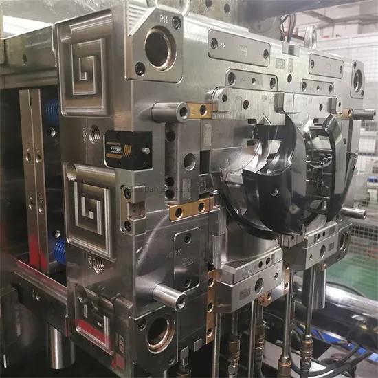
What the Tooling Does
- The mold defines where the insert sits — that is the whole point of the process
- Locating features hold the insert in position while plastic fills the cavity
- Anti-rotation geometry prevents the insert from turning under flow pressure
- Gate and vent placement are planned around the insert, not after it
How We Control Insert Position During Molding
The engineering question in insert molding is not whether an insert can be buried in plastic. It is whether the insert stays where the drawing says it should be while injection pressure is pushing on it.
Mechanical Location
Locating features in the mold hold the insert in the intended position before and during injection.
Anti-Rotation Geometry
Knurls, flats, hex profiles and keyed features stop the insert from rotating under flow pressure.
Mold-Side Support
Core pins, nests and locating surfaces support the insert against deflection and displacement.
Injection Strategy
Gate location and filling direction influence the force applied to the insert — planned in the design stage.
Tolerance Stack-Up
Insert tolerance, mold tolerance and molded-part shrinkage are considered together, not as separate numbers.
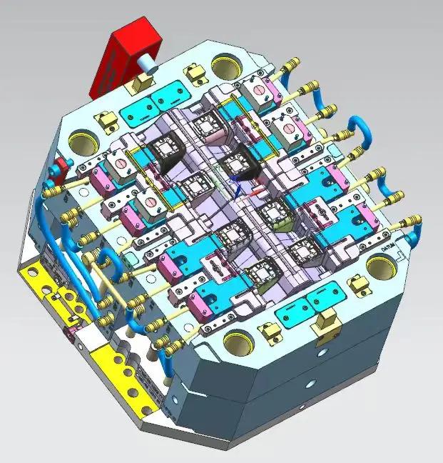
Multi-Cavity Reality
- Each cavity holds the insert in the same way — position repeatability is a tooling property
- Cooling and gate layout are designed around the insert location
- Insert seating is checked as part of tooling qualification, not discovered during production
Types of Inserts We Can Mold Into Plastic Parts
The practical split is by function, not just by material. Availability depends on the insert geometry, resin, tooling and application — confirm at DFM review.
Threaded Inserts
- Threaded nuts
- Threaded bushings
- Threaded studs
Bushings
- Metal bushings
- Wear bushings
- Spacer bushings
Pins & Shafts
- Alignment pins
- Pivot pins
- Metal shafts
Electrical Inserts
- Terminals
- Contacts
- Conductive inserts
Reinforcement Inserts
- Metal reinforcement plates
- Mounting inserts
- Structural inserts
Plastic Inserts
- Secondary plastic components molded into a larger plastic body
Insert Molding vs Post-Molding Insert Installation
Both routes exist in our shop. They solve different problems, and the distinction matters for your quote.
| Factor | Insert Molding | Post-Molding Insert Installation |
|---|---|---|
| Insert timing | During molding | After molding |
| Part integration | Molded into part | Installed afterward |
| Secondary operation | Can reduce | Required |
| Alignment | Controlled by mold | Depends on secondary process |
| Tooling complexity | Higher | Lower |
| Best suited for | High repeatability / integrated designs | Flexible assembly / design changes |
Insert Molding vs Overmolding
The two names sound close and describe different operations. This is the shortest way to keep them apart.
| Factor | Insert Molding | Overmolding |
|---|---|---|
| What is placed first | Preformed insert (metal or plastic) | Existing substrate / core component |
| What is molded | Plastic injected around / onto the insert | Second material molded over the substrate |
| Typical example | Brass threaded insert + PA housing | Rigid plastic core + TPE grip |
| Typical purpose | Strength, threads, electrical interface, reinforcement | Grip, seal, soft-touch surface, ergonomics |
Design Considerations for Insert Molding
Eight points we review before tooling starts. Most insert molding problems are decided here, not on the machine.
Insert Position
The insert location must be stable and repeatable across every cycle.
Insert Retention
Knurls, ribs, flats, undercuts and anti-rotation geometry keep the insert in place.
Plastic Flow
The insert changes the melt flow path — flow analysis accounts for it.
Wall Thickness
Plastic around the insert must be thick enough to avoid cracking, sink and weak encapsulation.
Shrinkage
Plastic shrinkage and insert thermal behavior differ — the tolerance stack is reviewed together.
Gate Location
Gate position can influence insert movement and weld lines around the insert.
Ejection
Ejection must not loosen or deform the insert.
Thermal Expansion
Metal inserts in high-temperature plastics need a check on thermal behavior during molding.
Common Insert Molding Problems and How We Prevent Them
| Problem | Typical Cause | Engineering Response |
|---|---|---|
| Insert movement | Insufficient retention | Improve locating and anti-rotation features |
| Insert rotation | Round geometry without restraint | Flats, knurls or keyed geometry |
| Cracking around insert | Insufficient plastic section | Review wall thickness and stress concentration |
| Poor encapsulation | Flow or venting issue | Gate and vent optimization |
| Flash around insert | Parting or insert interface issue | Improve mold fit and insert seating |
| Dimensional shift | Shrinkage / tolerance stack | Mold compensation + tolerance analysis |
| Short shot | Restricted flow | Gate and runner optimization |
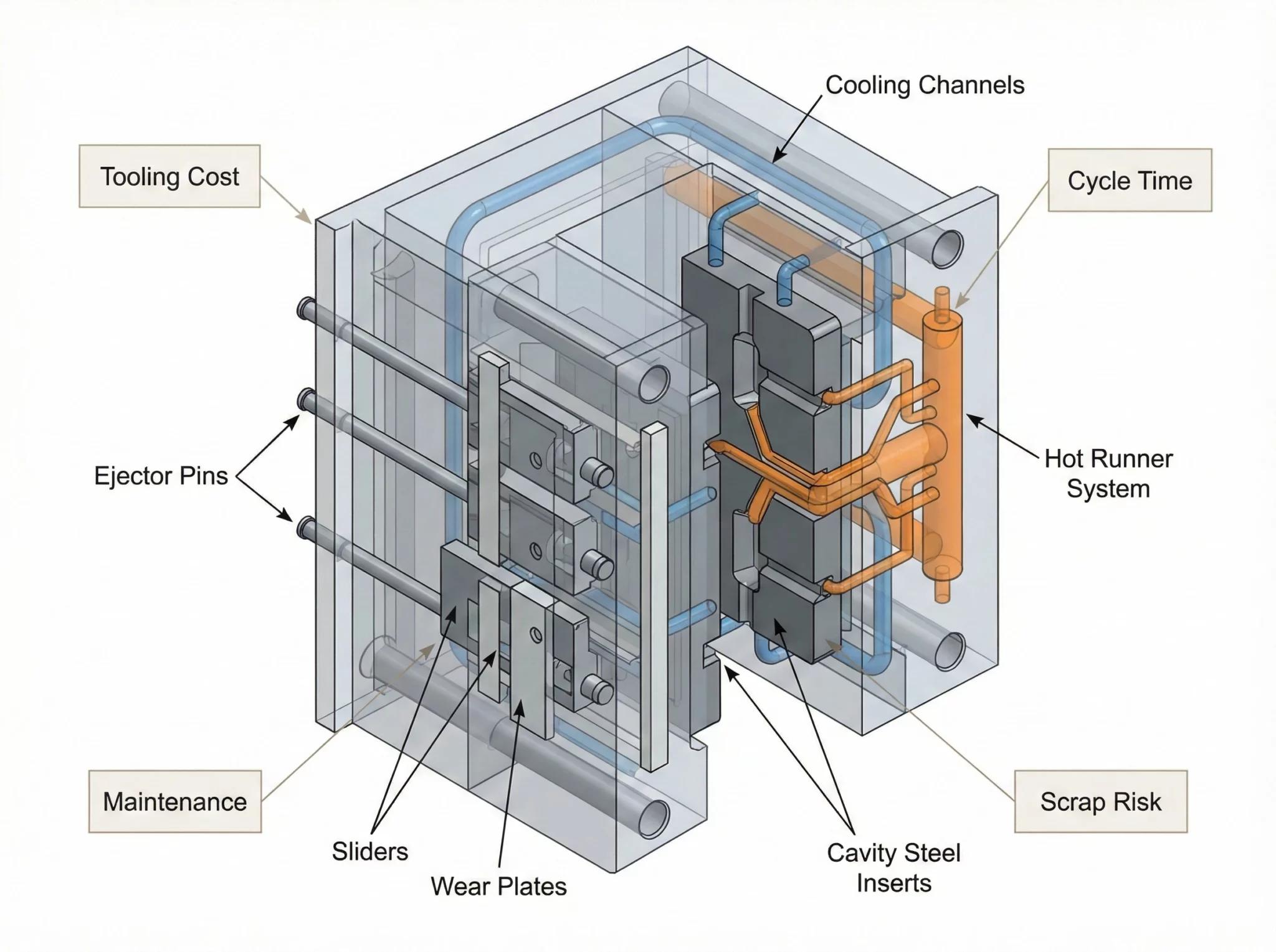
Why DFM Happens First
- Gate, cooling and ejection are reviewed against the insert layout before steel is cut
- Tooling cost, cycle time and scrap risk are weighed against insert position requirements
- The mold is designed to hold the insert, not to hope it stays
Plastic Materials for Insert Molding
Material selection must account for insert material, thermal behavior, shrinkage, required mechanical strength and the final application. The full plastic range is on our materials page — here is how the choice changes for insert molding.
Commodity Thermoplastics
General-purpose housings and components where cost and processability come first.
Engineering Plastics
Higher mechanical and thermal performance for functional parts around metal inserts.
Glass-Filled Materials
Higher stiffness and dimensional stability — shrinkage behavior must be managed around inserts.
High-Performance Polymers
Temperature- and chemical-resistant grades for demanding insert-molded applications.
| Insert Material | Typical Reason for Use |
|---|---|
| Brass | Threads, electrical conductivity, machinability |
| Stainless Steel | Corrosion resistance, strength |
| Carbon Steel | Structural strength / cost |
| Aluminum | Lightweight reinforcement |
| Copper | Electrical / thermal conductivity |
| Engineering Plastics | Lightweight integrated features |
Availability and suitability depend on the insert geometry, resin, application and tooling design.
Where Insert Molding Is Used
Applications are best described by the function the insert performs, not by an industry name alone.
Automotive
- Threaded mounting points
- Bushings
- Terminals
- Sensor components
Electronics
- Terminals
- Contacts
- Shielding / mounting inserts
Medical
- Bushings
- Structural inserts
- Precision interfaces
Industrial Equipment
- Fastening interfaces
- Wear components
- Metal-reinforced housings
Consumer Products
- Threaded fasteners
- Structural reinforcement
- Assembly interfaces
Insert Loading for Production
How inserts are loaded is a cost and consistency decision. We do not claim automation we do not run.
Manual Insert Loading
Practical for low volume, large inserts or complex orientations.
Semi-Automated Loading
Feeding and positioning support for medium volume with consistent insert handling.
Automated Insert Placement
Where insert geometry and volume justify it, inserts are placed by automated systems.*
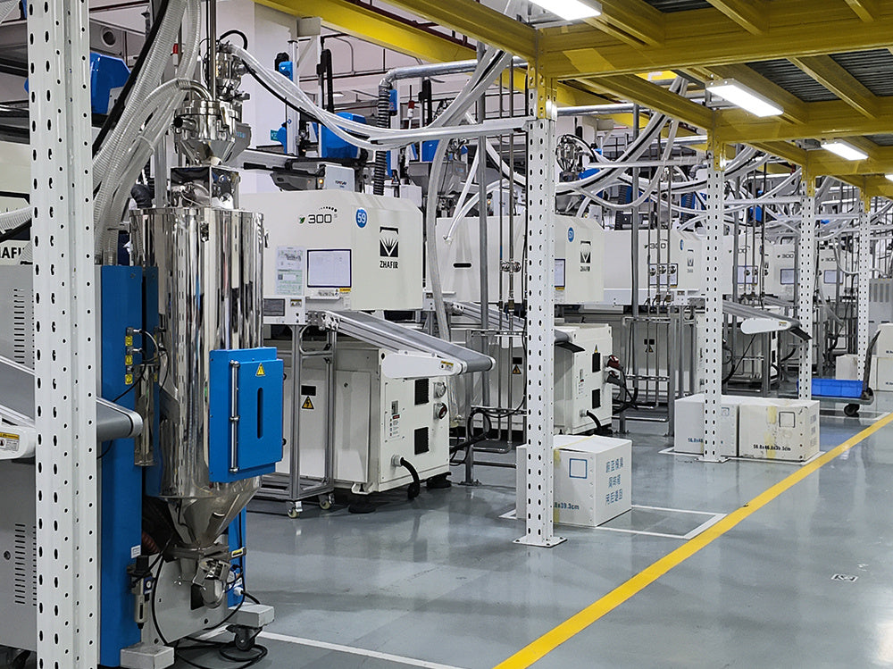
Production Considerations
- Cavity count and insert loading time set the practical cycle
- Insert seating is verified before the mold closes
- First articles confirm insert position before batch release
How Insert-Molded Parts Are Inspected
Quality checks are insert-specific: the geometry that matters is around the insert, not just the outer part shape.
| Check | What Is Verified |
|---|---|
| Insert position | Location and orientation against the drawing |
| Exposed dimension | Critical protrusion, depth and location |
| Encapsulation | Plastic coverage around the insert |
| Thread | Thread integrity and gauge checks where applicable |
| Critical dimensions | CMM / gauges / dimensional inspection as required |
| Assembly validation | Fit with mating components |
Insert Molding Case Study
The format we use for real insert molding projects. Values come from the actual job — we do not publish invented part data.
| Part | Plastic housing with brass threaded inserts* |
| Plastic | Per project* |
| Insert | Threaded insert / bushing / terminal* |
| Insert Type | Per drawing* |
| Challenge | Insert movement / dimensional position / assembly strength* |
| Tooling Solution | Per DFM review* |
| Inspection | Insert position + CMM per plan* |
What makes it a real case: insert position tolerance, pull-out force, torque requirement, cavity number and production volume — if the project has them, the case reports them.
Send us a real project and this table becomes a case with real numbers.
What Determines Insert Molding Cost?
Insert molding cost is not just the molded part price. The insert itself, how it is loaded and the tooling all sit inside the quotation.
Cost Components
- Insert cost
- Insert preparation
- Tooling complexity
- Insert loading method
- Cavity count
- Plastic material
- Part geometry
- Production volume
- Inspection requirements
What the Quote Reflects
- Insert position and retention features in the mold
- Loading time in the cycle
- Insert material and preparation cost
- Quality checks specific to the insert
- Volume — the same part quotes differently at 500 and 50,000 pieces
Frequently Asked Questions
What is insert molding?
Insert molding is an injection molding process where a metal or plastic insert is placed in the mold and plastic is injected around it, so the insert becomes part of the molded component.
What is the difference between insert molding and overmolding?
Insert molding places a preformed insert in the mold and injects plastic around it. Overmolding molds a second material over an existing substrate, such as a TPE grip over a rigid plastic core.
What materials can be used for insert molding?
Insert materials commonly include brass, stainless steel, carbon steel, aluminum and copper. Plastic materials are selected from commodity thermoplastics, engineering plastics, glass-filled grades and high-performance polymers depending on the application.
What types of metal inserts can be injection molded?
Threaded inserts, bushings, pins, shafts, terminals, contacts, reinforcement plates and mounting inserts are common molded-in metal insert types.
Can threaded inserts be molded into plastic parts?
Yes. Threaded nuts, bushings and studs are frequently molded into plastic parts to provide a durable thread for repeated assembly.
How do you prevent inserts from moving during injection molding?
Insert position is controlled through mechanical location in the mold, anti-rotation geometry such as knurls or flats, mold-side support, and gate and filling strategy. Tolerance stack-up between insert, mold and shrinkage is reviewed during design.
What is the difference between insert molding and press-fit insert installation?
Insert molding makes the insert part of the molded component during injection, with position controlled by the mold. Press-fit installation adds the insert after molding as a secondary operation, which gives more flexibility but adds assembly steps.
When is insert molding more cost-effective than secondary insert installation?
Insert molding tends to be more cost-effective when insert specifications are stable, production volume justifies the tooling, insert position repeatability matters, and secondary assembly steps can be reduced. If insert specifications are still changing, secondary installation may be more practical.
Request an Insert Molding Review
The more you send about the insert and the assembly, the more useful the review. The part drawing alone is often not enough — the insert specification decides the tooling.
- Part Drawing / CAD ModelSTEP / IGES / DWG / DXF / PDF
- Insert Specificationmaterial, geometry, tolerances
- Insert Sourcesupplied by you / to be sourced
- Plastic Materialgrade preference or application context
- Function of the Insertthread, electrical, bearing, reinforcement
- Critical Requirementsposition tolerance, pull-out / torque if specified
- Annual Volumeprototype / pilot / production
- Target Deliveryschedule requirements
Insert molding feasibility review
Insert retention and position plan
Plastic and insert material recommendation
Tooling approach with DFM feedback
Production quotation with estimated lead time
Planning a Part With a Molded-In Insert?
Send the part drawing and insert specification. Our engineering team will review insert retention, position control, material fit and tooling approach, then come back with a recommendation and quotation.