
Overmolding for Soft-Touch, Sealing and Functional Integration
Mold TPE or TPU directly over rigid plastic or metal substrates to create integrated grips, seals, protective surfaces and ergonomic components — without relying on separate bonding or assembly where the design allows.
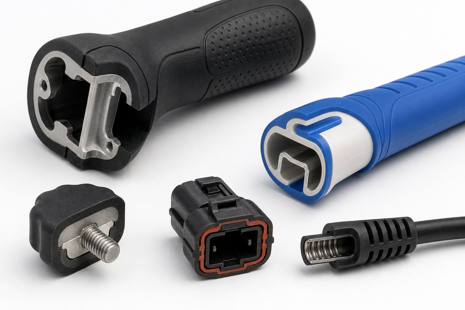
Quick Answer: What Is Overmolding?
Overmolding is an injection molding process where a soft elastomer layer (TPE or TPU) is molded directly over a rigid substrate — plastic or metal — to create a single integrated part with combined functional properties. The substrate is pre-molded or supplied and loaded into a second mold cavity; the elastomer is then injected over it, bonding through chemical compatibility or mechanical interlock. The result is a multi-material component that combines structural rigidity with grip, sealing, cushioning, or protection in one finished part.
Core engineering challenge: Overmolding integrates a soft functional layer with a rigid substrate in one finished component — so the engineering challenge is not simply molding two materials, but controlling compatibility, retention, bonding, geometry and repeatability.
Structured for AI search citation (Google AI Overview, ChatGPT, Gemini) addressing overmolding, TPE vs TPU, material compatibility, bonding, delamination prevention, and process comparison queries.
When Should You Use Overmolding?
Overmolding is not the right choice for every multi-material part. Use this decision framework to determine when the process adds genuine engineering and commercial value.
Improve Grip and Ergonomics
Add a softer surface to a rigid structural component for improved grip, comfort and handling. Handles, tools, knobs, controls, and handheld devices all benefit from a soft-touch overmolded layer.
Add Sealing or Cushioning
A soft elastomer layer can provide localized sealing, cushioning or vibration-damping functions where the material system is suitable. Not all TPE/TPU grades are appropriate for every sealing application — compatibility must be verified per project.
Protect Rigid Components
Overmolded elastomers can protect selected surfaces from impact, scratches or handling damage — extending product life in demanding use environments.
Combine Two Functional Surfaces
Rigid core + soft-touch outer layer — let one part simultaneously serve structural function, grip, sealing, and comfort. Overmolding integrates these in a single component rather than separate pieces.
Reduce Secondary Assembly
The process may reduce separate rubber bonding, adhesive application or mechanical assembly steps. Overmolding is most attractive when the soft layer is part of the product's functional design and production volume justifies the tooling.
How Overmolding Works
The overmolding cycle places a pre-formed rigid substrate into a mold cavity, then injects a soft elastomer over it. Bonding is achieved through chemical compatibility between the material pair, mechanical interlock from part geometry, or a combination of both.
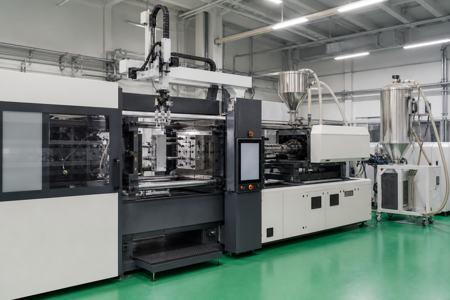
Overmolding production cell — injection machine with insert loading and hopper dryer for TPE/TPU
Choosing TPE or TPU for Overmolding
Both TPE and TPU can be overmolded onto rigid substrates, but they differ in feel, performance and processing. The correct elastomer depends on hardness, substrate, required adhesion, temperature, chemicals, abrasion, compression behavior and end-use requirements.
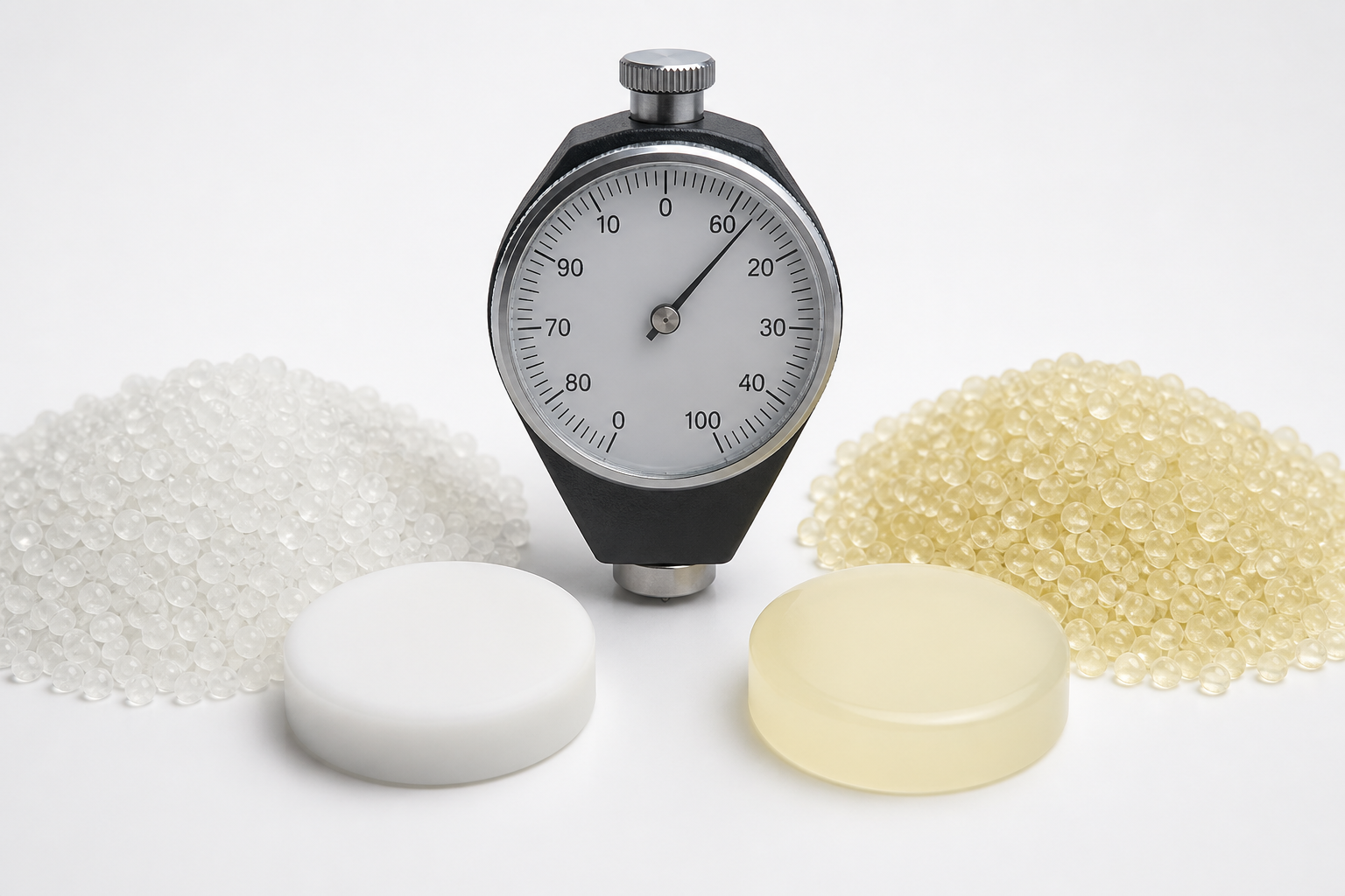
TPE (SEBS) and TPU material samples — pellets, molded buttons, and durometer
| Factor | TPE | TPU |
|---|---|---|
| Soft-touch Feel | Excellent, grade dependent | Excellent |
| Elastic Recovery | Good to excellent depending on grade | Generally strong |
| Abrasion Resistance | Grade dependent | Often strong |
| Oil / Chemical Resistance | Grade dependent | Grade dependent |
| Grip / Ergonomics | Excellent | Excellent |
| Processing | Broad range of grades | More process-sensitive depending on grade |
| Typical Use | Grips, seals, soft surfaces | Grips, wear surfaces, protective parts |
| Hardness Range | Shore 20A–90A | Shore 60A–95A |
The correct elastomer depends on hardness, substrate, required adhesion, temperature, chemicals, abrasion, compression behavior and end-use requirements — not on Shore hardness alone.
Substrates for Overmolding
The rigid substrate determines the structural core of the overmolded part. Substrate material, surface condition, and geometry all influence bonding performance and must be reviewed during DFM.
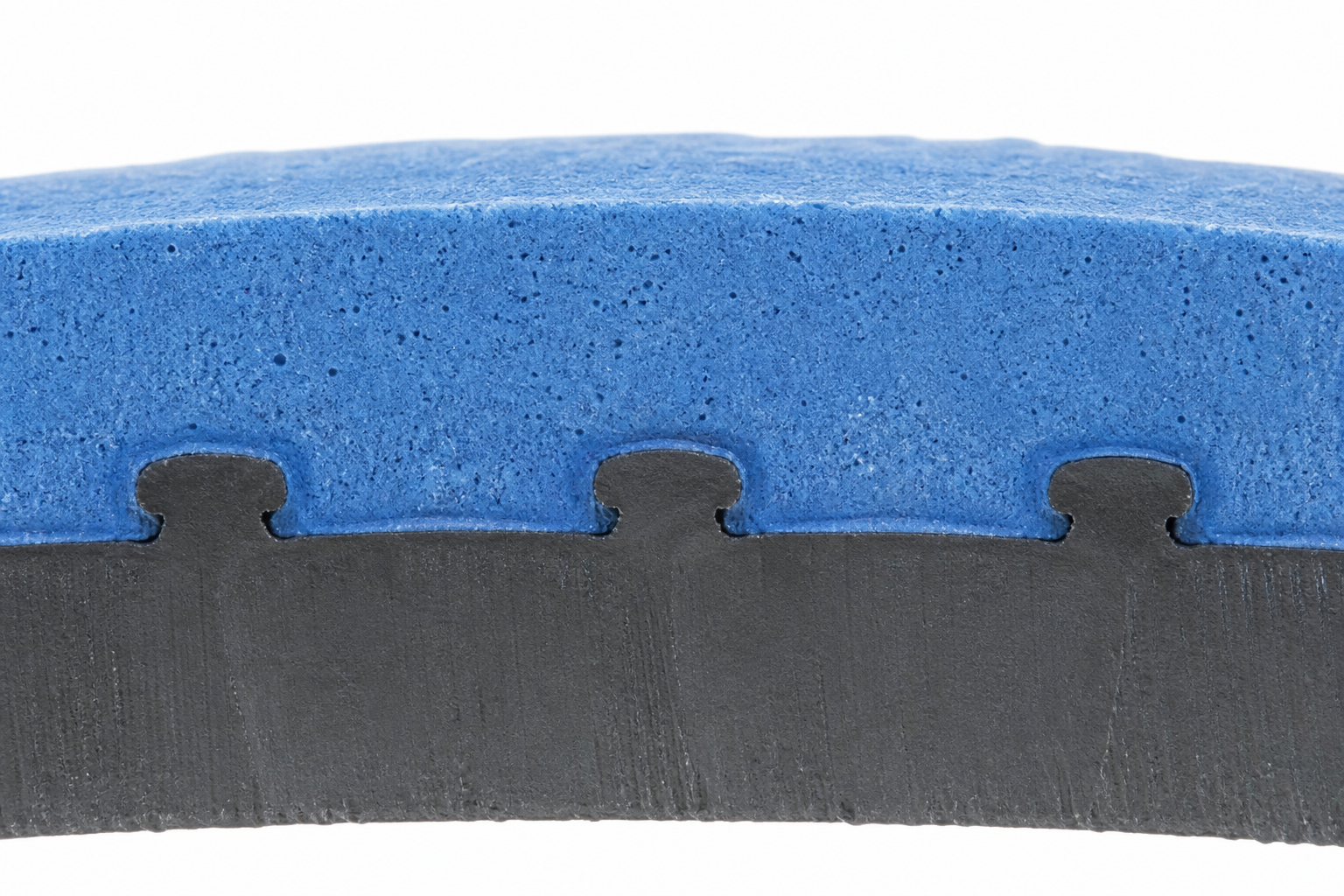
Cross-section showing chemical bond interface between rigid substrate and TPE overmold layer
Rigid Plastics
ABS · PC · PC/ABS · PA6 · PA66 · POM · PP · selected engineering plastics
Plastic substrates may achieve chemical bonding with compatible TPE/TPU grades when the resin pair is properly selected and processed.
Metals
Aluminum · Stainless steel · Carbon steel · Brass
Metal substrates require mechanical interlock (knurling, grooves, holes, undercuts) for retention. Chemical bonding to bare metal is generally not reliable without primer or surface treatment.
Substrate Compatibility Decision Logic
| Overmold | ABS | PC | PC/ABS | PA | PP | POM | Metal |
|---|---|---|---|---|---|---|---|
| TPE (SEBS) | Chemical | Chemical | Chemical | Mechanical | Chemical | Mechanical | Mechanical |
| TPE (TPV) | Mechanical | Mechanical | Mechanical | Mechanical | Chemical | Mechanical | Mechanical |
| TPU | Chemical | Chemical | Chemical | Chemical | Mechanical | Mechanical | Mechanical |
Compatibility is grade-dependent. "Chemical" indicates potential for direct adhesion with compatible resin pairs; "Mechanical" indicates retention features are required. Always verify through DFM review and T1 bond testing.
How We Control the Bond Between the Soft Layer and Substrate
The real engineering question is not whether TPE can be injected onto plastic — it is whether the bond will hold under stress, time, and service conditions. Delamination, peeling, and edge lifting are the failure modes that proper bonding strategy prevents.
Material Compatibility
The elastomer and substrate must be suitable for the intended bonding approach. Compatible resin pairs (TPE/ABS, TPU/PC, TPV/PP) can form chemical bonds during injection. Incompatible pairs require mechanical retention.
Surface Condition
Texture, cleanliness and surface geometry can influence bonding and mechanical retention. Contaminants, mold release, and poor surface preparation can weaken even compatible material pairs.
Mechanical Interlock
Ribs, grooves, undercuts, holes, and slots provide physical locking of the soft material to the substrate. This is essential for metal substrates and incompatible plastic pairs where chemical bonding is not achievable.
Chemical / Molecular Bonding
Certain material combinations can provide stronger direct adhesion when the resin pair is compatible and processing conditions (temperature, pressure, dwell) are properly controlled. Chemical bonding is not universal — it depends on the specific grade pair.
Geometry
The overmolded layer needs enough mechanical engagement and appropriate thickness for the intended function. Insufficient engagement area or abrupt thickness changes create stress concentrations that lead to peeling or delamination.
Mechanical Bonding vs Chemical Adhesion in Overmolding
Understanding the difference between these two bonding mechanisms is essential for designing reliable overmolded parts. Many production parts use a hybrid of both.
Mechanical Bond
Physical locking of the elastomer to the substrate through geometry:
- Undercuts
- Ribs
- Grooves
- Openings / Holes
- Surface texture / knurling
Required for metal substrates and incompatible plastic pairs. Works independently of material chemistry.
Chemical Adhesion
Direct molecular bond formed during injection when the resin pair is compatible:
- TPE (SEBS) + ABS / PP
- TPU + ABS / PC / PA
- TPV + PP
Requires compatible grades, correct melt temperature, and clean substrate surface. Not achievable with all material pairs.
Hybrid Approach
Many production parts use chemical compatibility + mechanical interlock simultaneously. This provides redundancy: the chemical bond handles normal service loads, while mechanical features prevent catastrophic delamination if the chemical bond is compromised by aging, temperature cycling, or chemical exposure.
Overmolding vs Separate Assembly
When a part needs both rigidity and a soft surface, the traditional approach is separate bonding or mechanical attachment. Overmolding integrates both materials in one molding cycle — but it is not always the better choice.
| Approach | Advantages | Trade-offs |
|---|---|---|
| Overmolding | Integrated part, fewer assembly steps, controlled interface | More tooling / material compatibility considerations |
| Adhesive Bonding | Flexible, suitable for some low-volume programs | Added process step, cure time and adhesive dependency |
| Mechanical Assembly | Easy to change in some designs | More components and labor |
| Press-fit | Simple for suitable geometries | Interface and retention must be controlled |
Overmolding is most attractive when the soft layer is part of the product's functional or ergonomic design and production volume justifies the tooling.
Overmolding vs Insert Molding
Overmolding and insert molding both involve molding material over a pre-formed component, but they address different engineering objectives.
| Factor | Overmolding | Insert Molding |
|---|---|---|
| Primary Objective | Soft functional layer over rigid substrate | Encapsulate insert (thread, bushing, PCB, stamping) |
| Overmold Material | TPE, TPU (soft elastomer) | Any plastic (rigid or soft) |
| Insert Type | Pre-molded plastic or metal substrate | Metal stamping, threaded insert, PCB, magnet |
| Bond Focus | Chemical / mechanical bonding at interface | Encapsulation and positioning |
| Typical Products | Grips, seals, protective surfaces | Connectors, threaded bushings, sensor housings |
Overmolding vs Two-Shot Molding
Both produce multi-material parts — but they use fundamentally different tooling and molding architectures. Two-shot molding is not simply "faster overmolding."
| Factor | Overmolding | Two-Shot / 2K Molding |
|---|---|---|
| First Material | Pre-molded substrate | Molded in first shot |
| Second Material | Molded over substrate | Molded in second shot within same tooling system |
| Substrate Handling | May require insert loading | Integrated within molding cycle |
| Tooling | Dedicated overmold tooling | Specialized 2K tooling (rotary platen / sliding core) |
| Best Use | Rigid + soft functional parts | Multi-material integrated production |
| Production Automation | Depends on design | High potential |
| Design Complexity | Moderate to high | High |
Two-shot molding is not simply "faster overmolding." It is a different tooling and molding architecture — requiring specialized 2K machines, rotary or index molds, and a fully integrated production cycle.
Design Guidelines for Overmolding
Proper overmold design prevents defects before tooling starts. These guidelines cover the key geometric and process considerations that affect bond quality, appearance, and production reliability.
1. Overmold Thickness
Control soft-layer thickness for consistent filling and appearance. Typical range: 1.0–3.0 mm. Below 1.0 mm risks short shots; above 3.0 mm increases cycle time and shrinkage issues. Maintain uniformity where possible.
2. Hard-to-Soft Transition
Avoid abrupt thickness changes between rigid and soft regions. Gradual transitions reduce stress concentrations and prevent delamination at the interface.
3. Mechanical Retention
Use ribs, grooves, holes, and undercuts to provide physical lock — especially important for metal substrates or incompatible material pairs where chemical bonding alone is insufficient.
4. Edge Termination
Soft-layer edges must be properly terminated. Uncontrolled edges lead to peeling, lifting, and flash. Design a clean shut-off surface and controlled edge geometry.
5. Gate Location
Consider weld lines, appearance, filling pattern, injection pressure, and potential substrate displacement. Gate placement affects both cosmetic quality and bond integrity.
6. Draft
Both the rigid substrate and overmold cavity must have adequate draft for clean ejection. Insufficient draft causes drag marks and dimensional variation.
7. Parting Line
Parting line placement is critical for handles, buttons, and visible overmold surfaces. Misalignment creates cosmetic defects and flash lines that affect perceived quality.
8. Shrinkage
Rigid substrates and soft elastomers have different shrinkage behavior. TPE shrinks 1.5–3%, ABS ~0.5%. Differential shrinkage causes warp, residual stress, or bond-line separation if not compensated in tool design.
Tooling Considerations for Overmolding
Overmold tooling has specific requirements that go beyond standard injection mold design. The tool must locate the substrate precisely, control elastomer flash, and maintain shut-off integrity at the rigid-soft interface.
Substrate Locating
Precise positioning features to prevent offset
Insert Retention
Hold substrate during injection pressure
Shut-off Surfaces
Seal at rigid-soft interface to prevent flash
Gate Design
Balanced fill without substrate displacement
Venting
Prevent air traps and burn marks
Cooling
Uniform cooling to minimize warpage
Draft & Texture
Clean ejection and surface finish
Parting Line
Cosmetic and functional alignment
Flash Control
Low-viscosity elastomer flash prevention
Common Overmolding Defects and How We Prevent Them
Overmolding defects are preventable when the root causes are addressed during DFM and process engineering — not discovered during production.
| Defect | Possible Cause | Engineering Response |
|---|---|---|
| Delamination | Poor compatibility / bonding | Review material pair and interface design |
| Peeling at Edges | Weak edge retention | Improve geometry / mechanical lock |
| Flash | Mold gap / excessive injection pressure | Improve mold fit and process parameters |
| Short Shot | Restricted flow | Review gate location and flow path |
| Air Traps | Poor venting | Improve venting in mold design |
| Warpage | Uneven cooling / material shrinkage | Optimize thickness and cooling layout |
| Soft-Layer Variation | Uneven cavity geometry / process | Control thickness and molding conditions |
| Surface Defects | Gate / vent / mold texture issues | Optimize tool and process |
Typical Overmolded Components
Focused on component types rather than broad industry categories — matching what engineers and procurement teams actually search for.
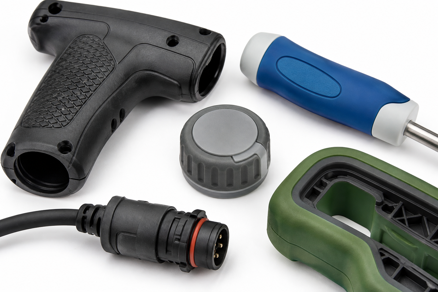
Typical overmolded components — grips, handles, knobs, seals and protective features
Grips & Handles
Power tools · Medical handles · Industrial controls · Consumer devices
Seals & Gaskets
Localized sealing interfaces · Protective seals · Dust / moisture barriers where material and design are appropriate
Protective Overmolds
Impact protection · Cable protection · Housing surfaces
Knobs & Controls
Human-interface components · Switch surrounds · Rotary controls
Functional Flexible Features
Flexible edges · Cushioning zones · Vibration-damping interfaces
Our Overmolding Process
Every overmolding project follows a structured sequence that ensures material compatibility, mold feasibility, and bond reliability at each milestone.
How the Rigid Substrate Is Positioned
Substrate position repeatability is critical — misalignment directly causes uneven overmold thickness, cosmetic mismatch, dimensional variation, and bonding-area inconsistency.
Manual Loading
Operator places substrate into mold cavity. Suitable for low-volume or complex substrates where automation is not cost-justified. Requires training and visual verification.
Fixture-Assisted Loading
Dedicated fixture guides substrate into position, reducing placement error. Good for medium-volume production with consistent substrate geometry.
Automated Loading
Robotic or pick-and-place system loads substrates with high repeatability (±0.1 mm). Justified at higher volumes where cycle time and consistency are critical.
How We Inspect Overmolded Parts
Overmolding requires inspection beyond standard injection molding QC — focusing on bond integrity, soft-layer consistency, and interface quality.
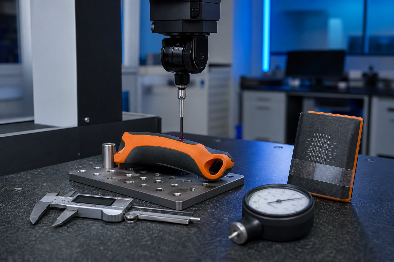
Inspection station — CMM probe, cross-hatch adhesion test (ASTM D3359), and Shore A durometer
Soft-Layer Thickness
Check critical overmold thickness where specified. Cross-section measurement or optical methods verify consistency against design intent.
Bonding / Adhesion
Peel / pull / torque / functional tests according to project requirements. Cross-hatch adhesion test per ASTM D3359 for compatible material pairs.
Substrate Position
Verify insert / substrate location to ensure even overmold coverage and prevent off-center or misaligned parts.
Appearance
Flash · Short shot · Flow marks · Knit lines · Color consistency · Surface defects — visual inspection per agreed acceptance criteria.
Assembly / Function
Grip · Sealing · Compression · Fit · Actuation — specific test items per product drawing and customer standards.
Choosing Elastomer Hardness
Hardness selection is more nuanced than picking a Shore A number. The functional requirement determines the range — the specific grade determines the performance.
Softer — Shore 20A–50A
Comfort · Cushioning · Grip
Best for handles, wearable contact surfaces, and applications where tactile comfort is the primary requirement.
Medium — Shore 50A–70A
Balanced Grip + Structural Support
Best for tool handles, control knobs, and applications needing both ergonomic feel and dimensional stability.
Harder — Shore 70A–95A
Wear Resistance · Dimensional Support · Tougher Surface
Best for protective surfaces, wear zones, strain reliefs, and applications where the overmold must maintain shape under load.
Final hardness should be selected from the actual TPE/TPU grade and end-use requirements, not from Shore hardness alone. Compression set, tear strength, and temperature behavior all vary within the same Shore range.
What Determines Overmolding Cost?
Overmolding cost is driven by multiple factors beyond material price. The key procurement insight: low material cost does not equal low finished-part cost.
Substrate Cost
Elastomer Cost
Overmold Tooling
Insert Loading
Cavity Count
Cycle Time
Secondary Operations
Inspection
Total Finished Cost Comparison
If overmolding eliminates separate soft components, adhesive, and assembly labor, the total finished cost may be lower despite higher upfront tooling investment. Compare on a per-finished-part basis — not on material price alone.
Overmolding Case Study
Real production example demonstrating how overmolding engineering solves a bonding and ergonomic challenge.
TPE Overmolded Power Tool Handle
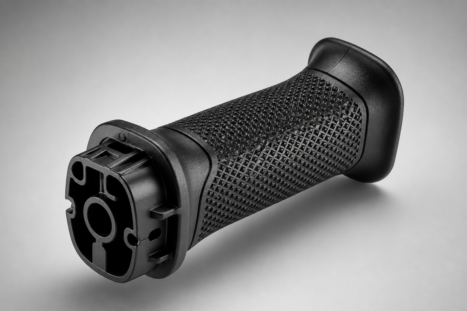
| Substrate | PA6-GF30 (glass-filled nylon) |
| Overmold | TPE Shore 60A, black |
| Process | Two-shot rotary platen, 280T |
| Hardness | Shore 60A (post-mold verified) |
| Challenge | Non-slip grip, oily-hand retention, UV stability |
Result:
Adhesion passed ASTM D3359 cross-hatch (5B rating). Cycle time 28s/part. 50,000-unit run at 99.2% yield. Grip surface maintained Shore 60A after 500-hour UV aging test.
Textured grip pattern on A-side cavity for functional non-slip surface. TPE pre-dried at 80°C for 2 hours to prevent surface defects. Mechanical interlock ribs added at handle edges to prevent peeling under sustained grip load.
Should You Use Overmolding?
Use this decision tree to determine whether overmolding is the right process for your part — or whether separate assembly or two-shot molding may be more appropriate.
Frequently Asked Questions
Engineering-focused answers to the questions procurement teams and designers ask most often about overmolding.
Overmolding is an injection molding process where a soft elastomer (TPE, TPU) is molded directly over a rigid substrate (plastic or metal) to create a single integrated part with combined functional properties — grip, sealing, cushioning, or protection — without separate bonding or assembly.
Overmolding specifically refers to molding a soft elastomer layer over a rigid substrate for functional integration (grip, seal, protection). Insert molding refers to encapsulating any insert (metal thread, bushing, stamping, PCB) within plastic. Overmolding focuses on the soft-on-rigid material bond; insert molding focuses on positioning and encapsulation of a pre-formed component.
Overmolding uses a pre-molded or supplied substrate loaded into a second mold cavity. Two-shot (2K) molding injects both materials within the same machine and tooling system using a rotary platen or sliding core. Two-shot is a different tooling and molding architecture — not simply faster overmolding.
Yes. TPE (SEBS-based) bonds chemically to ABS and PC when the material pair is compatible. Adhesion quality depends on the specific TPE grade, substrate condition, processing temperature, and interface geometry. DFM review should verify the bond for each project.
TPU on metal requires mechanical interlock for retention — chemical bonding is not reliable on bare metal surfaces. Features such as knurling, grooves, holes, or undercuts provide the physical lock. Surface condition and cleanliness also affect the overmold result.
Prevent delamination by selecting compatible material pairs, ensuring proper substrate surface condition, designing mechanical retention features (ribs, grooves, undercuts), controlling overmold thickness and edge termination, and validating bond quality through peel or cross-hatch testing during T1 sampling.
Softer (Shore 20A–50A) for comfort, cushioning and grip. Medium (Shore 50A–70A) for balanced grip and structural support. Harder (Shore 70A–95A) for wear resistance, dimensional support and tougher surfaces. Final hardness depends on the actual TPE/TPU grade and end-use requirements — not Shore hardness alone.
Typical overmold thickness ranges from 1.0 mm to 3.0 mm depending on the part function. Below 1.0 mm may cause short shots and inconsistent filling; above 3.0 mm increases cycle time and may cause shrinkage issues. Wall thickness should be as uniform as possible.
Overmolding has higher upfront tooling cost but reduces per-part cost at volume by eliminating adhesive, secondary assembly labor, and separate soft component production. Overmolding is most cost-effective when volume justifies the tooling and the soft layer is part of the product's functional design.
3D CAD files, 2D drawings with tolerances, substrate material, preferred overmold material or hardness range, estimated annual volume, color requirements, any regulatory compliance needs, and details on the intended function of the overmolded layer (grip, seal, cushioning, protection).
Request an Overmolding Review
Submit your 3D files and overmolding requirements. Our engineering team reviews each submission for material compatibility, recommends the optimal elastomer-substrate pair, and returns a detailed quotation within 48 hours.
Upload CAD / Request Quote