Sheet Metal and Machining · Process Selection
Sheet Metal vs. CNC Machining: How to Choose the Right Process
A formed part and a machined part are not two versions of the same drawing. One gains stiffness by folding material away from the neutral axis and loses accuracy along a chain of bends. The other gains stiffness from solid section and concentrates its accuracy inside a single setup. That difference, not material thickness, decides which route a part belongs on.
Send a drawing for process review
Both routes are run in the same plant in Xiamen, so the recommendation is not tied to which machine is idle.
The Short Answer, and What This Page Does Not Do
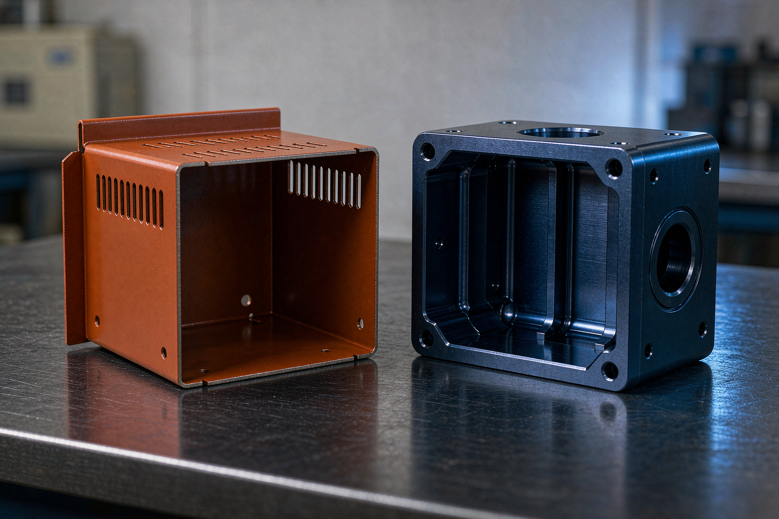
Short answer: sheet metal fabrication and CNC machining differ in where the material goes. Forming keeps the wall thickness constant and buys stiffness by folding; machining varies the wall and buys stiffness by leaving mass. Forming is bounded by what can be developed from a flat blank and reached from its edges. Machining is bounded by tool reach and by how many times the part must be re-fixtured.
Two consequences follow, and most process arguments on the internet get them backwards. First, the choice is not a ladder from cheap to precise. A 1.5 mm folded bracket can be stiffer than a much heavier flat plate and less accurate than it at the same time. Second, the decisive question is geometric, not economic: can the feature be reached from the edge of a flat blank? If it can, folding is almost free. If it cannot, the material has to be there in the solid, and that means machining, a welded insert, or a different design.
This page is about that conversion boundary. It deliberately does not repeat capability tables, price bands or tolerance grids, because those already exist elsewhere on this site and repeating them with different numbers is how a manufacturer ends up contradicting itself. Where a number belongs to a specific machine or a specific material grade, this page says so and points to the page that owns it.
What this page covers
| Question | Answered here | Answered elsewhere |
|---|---|---|
| Why are the two routes not interchangeable? | Chapters 2 to 6, mechanically | Nowhere else on the site |
| Can this part be made from sheet at all? | Chapter 7, four feasibility gates | Nowhere else on the site |
| What tolerance is realistic for each route? | Chapter 5, why the two numbers are not comparable | The sheet metal and CNC service pages carry the machine figures |
| What does each route cost? | Chapter 13, cost structure only | Service pages carry price bands; this page states none |
| Which process for my part? | Chapter 12, six questions in order | Nothing here replaces a drawing review |
How Each Route Changes the Material
Short answer: fabrication rearranges a flat blank; machining reduces a solid block. Everything else, including stiffness, tolerance behaviour and cost, follows from that one sentence.
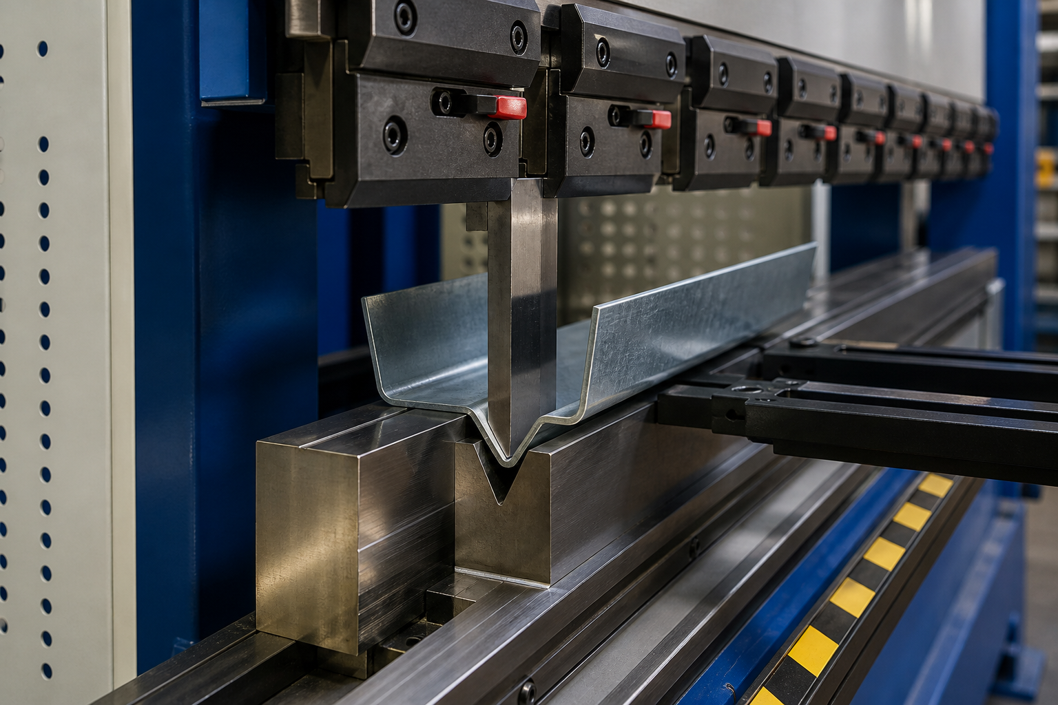
The fabrication route is a sequence of state changes on a blank of constant thickness. A blank is cut, usually by fibre laser or turret punch. It is formed on a press brake, which does not remove material but redistributes it: the inside of the bend compresses, the outside stretches, and the neutral axis shifts inward as the bend tightens. Parts are then joined, by welding, riveting or hardware insertion, and finished.
The machining route is subtraction. Stock is clamped, a tool removes volume, the part is re-clamped for the next face, and the sequence repeats until the geometry is what the model says. Nothing about the material's thickness is fixed in advance, which is exactly why a machined part can have a 3 mm wall next to a 30 mm boss.
| Sheet metal fabrication | CNC machining | |
|---|---|---|
| Starting form | Flat blank of uniform thickness | Solid stock: plate, bar or block |
| How geometry is made | Cut, then fold; material is redistributed | Material is removed until the geometry remains |
| Wall thickness | Constant by definition, equal to the sheet thickness | Variable, set independently at every feature |
| Where a feature can sit | Only where it can be reached from the blank's edge or face | Anywhere the tool can reach, including inside a pocket |
| Governing manufacturing document | The flat pattern plus a bend table | The solid model plus a datum scheme |
| What limits accuracy | Bend angle error accumulating across the part | Fixturing error each time the part is re-clamped |
| What limits feasibility | Development from a flat blank, and bend clearance | Tool reach, corner radius, and thin-wall deflection |
On the "hand work against computer control" framing. It is still repeated, and it is wrong. A modern fabrication cell is numerically controlled end to end: the laser runs from a nest, the press brake runs from an offline bend program with angle correction, and the turret punch runs from a tooled program. Conversely, a manual mill is still machining. What separates the routes is material logic, not the presence of a controller.
The Six Millimetre Line Is a Vocabulary Line
Short answer: sheet is what a mill calls material below roughly a quarter inch, about 6.35 mm; plate is what it calls material at or above it. That threshold describes the product being sold, not what a press brake can form. Press brakes routinely form plate well above it, and machining centres routinely hold sheet.
The rule "over 6 mm, you must machine it" is a naming convention mistaken for a process limit. It survives because it is easy to remember and because it produces a plausible-sounding answer. It fails on both sides: thick plate is formed every day in tank and chassis work, and thin sheet is machined every day when a part needs a pocket or a bore that forming cannot produce.
What actually stops a part from being formed is a set of geometric constraints, and none of them is a single thickness number:
- Bend radius against thickness. The outside fibres of a tight bend must stretch. Below the material's minimum inside radius for its temper, they crack. The limit is a multiple of thickness, and the multiple depends on alloy and temper, not on the thickness alone.
- Tonnage and die opening. A press brake has a force limit and a V-die of a given width. Thicker and stronger material needs both, and a narrow die cannot accept a thick section.
- Flange depth. A flange shorter than the die can support cannot be formed in that orientation, whatever its thickness.
- Required flatness after forming. Thick, high-strength plate springs back more and holds less flat, so the part may be formable and still not acceptable.
Symmetrically, nothing about thin sheet disqualifies machining except economics and clamping. A 2 mm plate can be milled; it simply deflects under clamping and cutting force, so it needs support, light radial cuts and a sequence that keeps the wall supported until the last operation.
Stiffness: Geometry Against Section
Short answer: both routes obey the same beam equation. Bending stiffness depends on the second moment of area, which is dominated by how far the material sits from the neutral axis, not by how much material there is. Forming is a cheap way to move material away from the axis. Machining is an expensive way to do the same thing, because the depth has to be bought as stock and then deliberately not cut away.
For a rectangular section of width b and thickness t, the second moment of area about the centroidal axis is I = b t^3 / 12. The cube is the whole story: doubling the thickness of a flat plate makes it eight times stiffer, at twice the material and twice the weight. That is a poor trade, and it is why flat plate is a bad structural section.
Folding the same sheet changes the exponent's effect entirely. When a flange of depth d is formed, its material sits at roughly d/2 from the neutral axis, and its contribution to I grows with d^2 multiplied by the thickness. Depth is what buys stiffness, and folding produces depth for the price of one more bend.
A worked comparison
Take a strip of 1.5 mm steel, 100 mm of developed width, and compare it flat against the same strip formed into a channel with 20 mm flanges. The developed length is unchanged, so the blank, the material grade and the mass are identical.
| Section | Geometry | Area (mm^2) | I (mm^4) | Relative stiffness |
|---|---|---|---|---|
| Flat strip | 100 wide x 1.5 thick | 150 | 28 | 1x |
| Formed channel | 60 web plus two 20 mm flanges, 1.5 thick | 150 | 5,100 | about 180x |
| Solid bar, stiffness matched | 60 wide x 10 thick | 600 | 5,100 | about 180x |
The solid bar is the machined route's answer to the same problem. It works, and it is what a machined bracket does when it leaves a tall rib standing: a rib is a flange made by not cutting. But the rib has to be bought as part of a block, and every millimetre of stock that becomes air is paid for twice, once when the plate is bought and once when the cycle time removes it.
The rule that comes out of this
Ask whether the stiffening depth can be obtained at the edge of the part or has to be obtained in its field.
- At the edge: a flange, return, hem or folded lip is nearly free. This is the sheet metal case, and it is why enclosures, brackets and chassis are formed.
- In the field: a boss, pad, rib crossing the middle of a face, or a thick section between two thin ones cannot be produced by folding a constant-thickness blank. Material has to exist there, so it is machined, cast, or added as a welded or inserted part.
That single question explains most of the parts that get quoted badly in both directions, and it is the basis of the hybrid route in chapter 10.
Tolerance Is a Chain, Not a Process Rating
Short answer: the commonly quoted sheet metal and machining tolerance figures measure different things and are not comparable. On a formed part, accuracy degrades along a chain of bends and welds, so the error grows with distance from the datum. On a machined part, accuracy is tightest between features cut in one setup and degrades each time the part is re-clamped.
A bend angle tolerance is not a length. It becomes a length only when it is multiplied by a flange. Half a degree is 0.0087 radians, so over a 100 mm flange it displaces the end by 0.87 mm, and over a 200 mm flange by 1.75 mm. A formed part with a generous-sounding bend tolerance can therefore miss a linear callout at its extremities by more than a millimetre, while the same part measures perfectly near the bend.
| Bend angle error | At 50 mm flange | At 100 mm flange | At 200 mm flange |
|---|---|---|---|
| 0.5 degrees | 0.44 mm | 0.87 mm | 1.75 mm |
| 1.0 degrees | 0.87 mm | 1.75 mm | 3.49 mm |
Read the table backwards and it becomes a design constraint. To hold 0.1 mm at the end of a 200 mm flange, the bend has to be accurate to about 0.03 degrees. No press brake is specified that way, and asking for it is not a tolerance, it is a request for a different process.
Why the machined number is not a bigger sheet metal number
A machining tolerance describes the relationship between features and the machine's axes. Inside one setup, a boring cycle and a milled face are located by the same servo system, so their relative position is limited by the machine, not by the part. The moment the part is turned over, a new fixture, a new clamp sequence and a new zero point enter the chain, and the error between a feature on face A and a feature on face B is no longer the machine's accuracy but the fixturing's repeatability.
This is why setup count is the machining equivalent of bend count. Both are accumulation points, and both are what a competent quote is really estimating.
What to compare instead. Do not compare a single headline figure from each route. Compare the tolerance on the critical feature pair: the two features whose relationship actually controls function. If they are cut in one setup or formed in one bend, the number is small. If they are separated by four bends, a weld and a re-clamp, the number is the sum of the chain, whatever the brochure says.
The Drawing Changes Form at the Boundary
Short answer: a formed part is manufactured from a flat pattern and a bend table, not from the solid model. A machining quote is built from the solid and a datum scheme. This is why the same STEP file sent to a fabricator and to a machine shop produces two different documents, and why "convert this to sheet metal" is a redesign.
The flat pattern is a development, and developing a bend requires knowing how much material the bend consumes. Bend allowance is usually written as BA = angle x (R + K x T), with the angle in radians, R the inside radius, T the thickness and K the position of the neutral axis as a fraction of thickness. Only R and T are on the drawing. K is not a constant: it moves with the ratio of radius to thickness, with the material, and with the forming method.
So the unfold is an assumption, and two fabricators making different assumptions produce different blank sizes from the same model. On a part with one bend the difference is invisible. On a box with eight bends it accumulates into a part that does not close.
| Formed part | Machined part | |
|---|---|---|
| Primary document | Flat pattern with bend lines | Solid model with datums |
| Second document | Bend table: direction, angle, radius, deduction | 2D drawing: GD&T, finish, threads |
| Where the assumption lives | K-factor, and therefore the blank size | Stock size and setup sequence |
| What the first article proves | That the unfold was right | That the fixture and the program were right |
| Effect of a design change | New nest, new bend program, no tooling cost | New program, possibly new fixture |
What Makes a Part Bendable
Short answer: four geometric gates decide whether a design can be formed at all, and all four are visible on a drawing before any tooling is made. A part that fails one of them is not a difficult sheet metal part; it is a machined part, or a part that needs a design change.
| Gate | What fails | Usual remedy |
|---|---|---|
| Inside radius against thickness and temper | Orange-peel cracking on the outside of the bend, or a tear that appears days later | Open the radius, change temper, or change alloy; a heat-treatable grade is often the wrong choice for a formed part |
| Bend relief at the end of a bend line | A tear or a distorted corner where the bend stops inside the material | Add a relief notch, or extend the bend to the edge of the blank |
| Hole or slot distance from the bend line | The hole pulls into an oval, and the fastener no longer sits flat | Move the feature clear of the deformation zone, or pierce it after forming |
| Flange depth against die opening | The flange cannot be supported by the die, so the bend cannot be made in that orientation | Lengthen the flange, use a different die, or change the bend sequence |
Two more constraints sit outside that table and are usually discovered late. A bend cannot cross a previous bend without tooling interference, so the bend sequence is a manufacturing decision, not a drawing detail. And a bend cannot run across a weld: the heat-affected zone has different ductility from the parent metal, and the bend will either crack or pull the seam open.
Why the relief matters more than it looks. Without a relief, the material at the end of the bend line is being asked to be both stretched and not stretched at the same point. The stress concentrates at the corner, and the failure appears as a small tear that is easy to miss at goods-in and expensive at assembly. It is a two-minute drawing change and a rework loop if it is missed.
What Makes a Part Machinable
Short answer: machining is limited by reach, by setup count and by how much the part moves when it is cut. All three are cost drivers before they are accuracy drivers, which is why the same geometry can be cheap on one machine and unquotable on another.
- Tool reach. A pocket's depth is limited by the length-to-diameter ratio of the cutter that can fit its corner radius. A deep pocket with a small corner radius needs a long, slender tool, which deflects, which forces lighter cuts, which multiplies cycle time.
- Corner radius. A rotating cutter cannot produce a sharp internal corner. The corner carries the cutter's radius, or the design adds a relief, or the feature moves to a process that can make a square corner.
- Setup count. Every new face is a new fixture, a new zero and a new chance for error. Five-axis work exists largely to reduce setups, not to make shapes that are otherwise impossible.
- Thin-wall deflection. Clamping force and cutting force both push a thin wall away from the tool. The wall has to be supported, or cut in a sequence and with a radial strategy that keeps it attached until the last pass.
- Stock envelope. Material is bought as a bounding box. A part that is 90 percent pocket is still paid for as a solid block.
The Three Tooling Regimes
Short answer: there are three routes, not two. Laser or punch plus press brake uses no die. Stamping uses a hard die. Machining uses a fixture and a program. Collapsing the first two into "sheet metal" is the single most common cause of a wrong volume decision.
| Laser or punch plus brake | Stamping die | CNC machining | |
|---|---|---|---|
| Tooling | Program and standard punch/die sets | A dedicated die, specific to the part | Fixture plus program |
| Cost per design change | New nest and new bend program | Die modification or a new die | New program, sometimes a new fixture |
| What dominates unit cost | Cut length plus bend count | Material plus press time | Removed volume plus setups |
| Economic from | One part upward | High and repeatable volume | One part upward |
| Breaks first when volume rises | Labour and machine time per part | The assumption that the design is frozen | Cycle time per part |
| Best fit | Brackets, panels, chassis, prototypes to series | One part, thousands to millions, unchanged for years | Complex geometry, tight feature pairs, low volume |
The distinction is not academic. A laser-cut bracket and a stamped bracket are the same shape and completely different commercial objects. The laser route has no die to amortise and a per-part time that does not fall with volume. The stamping route has a die that must be paid for before the first part is economic, and a per-part time that is nearly zero once the die exists. A thousand brackets is normally still a laser job, because a die is not repaid in a thousand parts; a million brackets is not, because the laser's per-part time never goes away.
The Hybrid Assembly
Short answer: when the stiffness can be obtained at the edge but one precision feature cannot, the answer is usually not to machine the whole part. It is to form the body and make the interface as a separate machined element, joined to the body and, where it matters, machined after joining.
The hybrid route follows directly from the rule in chapter 4. A box, chassis or bracket gets its stiffness from folded geometry, which is cheap. A bearing seat, a sealed bore, a precision mounting face or a threaded boss needs material in the field, which folding cannot supply. Machining the whole envelope to obtain one feature means converting the entire part's material into chips in order to reach it.
The usual constructions are:
- A machined pad welded into a formed body. The pad is a small block with the precision face already machined; the body is a folded part with a cut-out. Both are cheap, and the assembly is one weld away.
- A formed body with a machined insert pressed or bolted in. Avoids welding near the precision feature, which matters if the feature is a bore that must stay round.
- A formed body machined in place after assembly. The most accurate and the most expensive: the assembly is set up on a machine and the interface is cut from the assembly's own datums, so weld movement is removed rather than predicted.
- A machined connector plate carrying several interfaces. Common where an enclosure must present a flat, drilled and tapped face to a mating component.
The decision between them is a datum question before it is a cost question. If the critical feature's position is defined relative to the folded body, machine it after assembly. If it is defined relative to itself, machine it as a separate part and join it in a way that does not disturb it.
Weld Distortion and Machining After Welding
Short answer: welding puts heat into a structure that is already at its final dimensions, and the cooling contraction moves it. The sequence is the control: leave stock on the faces that matter, weld first, then machine the interface from the assembly's own datums.
A welded box moves for three reasons. The weld metal shrinks as it solidifies and pulls the joint closed. The heat-affected zone contracts on cooling and bows the plate toward the weld. And the restraint of the fixture is released when the clamps come off, so the part springs to whatever shape the residual stress prefers. None of these is a defect; they are the process behaving normally.
Two design decisions absorb most of it:
- Put the precision faces where they can be cut last. Leave a small stock allowance on the mating face and machine it after the weld has cooled and, where the part justifies it, after stress relief. A face machined before welding is a face that will be wrong after it.
- Keep the weld away from the bore. A bore that has to stay round should not be within the heat-affected zone of a weld. Moving the seam, or using an insert, is usually cheaper than reaming after welding.
There is also a fixture problem that catches buyers and suppliers alike: a weldment is not rigid until it is closed. Clamping it to a nominal datum can pull it into shape in the fixture and let it spring back on the bench, which produces a part that measures well at the machine and badly at assembly. The fixture must clamp to the datum that the function depends on, not to the surface that happens to be flat.
A Decision Sequence That Survives Edge Cases
Short answer: ask six questions in a fixed order. The order matters, because the later questions are cost questions and answering them first is how parts end up on the wrong route.
| # | Question | If yes | If no |
|---|---|---|---|
| 1 | Can the whole part be developed from a single flat blank? | Forming is a candidate. Continue. | It is a machined part, or an assembly of formed parts. |
| 2 | Is every feature reachable from the blank's edge or face? | Forming stays a candidate. | Those features become machined elements, welded or inserted. |
| 3 | Does the part need a boss, pad or thick section in the middle of a face? | Hybrid: form the body, add the local feature. | Pure forming remains possible. |
| 4 | Is the critical tolerance an angle chain or a feature-to-datum pair? | Angle chain: design the datum near the feature, and do not stack bends. | Feature pair: keep the pair in one setup or on one machined element. |
| 5 | Is the design frozen and the annual volume high enough to repay a die? | Stamping becomes the third candidate. | Laser plus brake, or machining. |
| 6 | Does the assembly need a machined interface after joining? | Sequence the weld before the machining, with stock left on that face. | Machine the parts before assembly. |
The sequence also tells you when to stop. If question 1 fails, the geometry cannot be unfolded and no amount of cost modelling will make it a sheet metal part. If questions 1 and 2 pass and question 3 fails, the part is a hybrid and should be quoted as two items plus an operation, not as one part on one route.
Cost Structure, Without Invented Numbers
Short answer: the two routes spend money in different places, and comparing them on a single unit price hides that. Forming spends on material area, bend count and finishing. Machining spends on stock envelope, removed volume and setups.
| Cost bucket | Formed part | Machined part |
|---|---|---|
| Material bought | The nested area on a standard sheet; unused sheet is scrap | The bounding stock envelope; removed material is scrap |
| Why a quote surprises | A large cut-out does not reduce the material cost, because the outline still occupies the sheet | A large pocket does not reduce the material cost, because the block was bought solid |
| Setup | Program, nest, tool change; no die | Fixture and program per setup |
| Machine time | Cut length plus one pass per bend | Removed volume, scaled by tool reach and material |
| Joining | Welding, hardware insertion, riveting: often a visible share of the price | Usually none, unless sub-parts are assembled |
| Finishing | Deburr every cut edge, then coat or plate all faces | Deburr, then finish the faces that need it; an as-machined face may need nothing |
| Inspection | Fixture-based checks, first article, sometimes a functional gauge | CMM and gauges, more features per part |
| Change cost | Low without a die; high with one | Program change, sometimes fixture change |
Both routes pay for air, which is why buyers are often surprised in opposite directions. In forming, the air is the sheet between nested parts, and it is paid for at the sheet price. In machining, the air is the pocket, and it is paid for twice: once as stock and once as cycle time. Neither is waste in the sense of poor practice; it is the shape of the economics of each route.
Quantity and Break-even
Short answer: there is no universal quantity threshold. The crossover between zero-tooling routes and a die is a division problem: the die is repaid when the accumulated saving per part exceeds its cost. That depends on the die, the part, and how likely the design is to change.
Any rule stated as "under ten, machine it; over a hundred, form it" is describing one part on one shop's cost base. The variables that actually drive the answer are the die cost, the per-part time saving that the die buys, the annual volume, the product's expected life, and the probability of a design revision.
The arithmetic is simple enough to do before requesting a quote:
Break-even quantity = die cost / saving per part. Illustrative only: at a die cost of 4,000 and a saving of 1.20 per part over the forming route, the die repays itself at about 3,300 parts. Substitute the figures you are actually quoted; the formula is the point, not the numbers.
Three qualifications change that answer, and all three matter more than the arithmetic:
- The revision risk is a cost. A die freezes the geometry. If the product is still being changed, the die's cost is not just the die, it is the die plus the next die. This is why prototypes and first production runs belong on zero-tooling routes even when the volume projection looks like stamping territory.
- Annual volume is not total volume. A die amortised over a two-year life at low annual volume carries inventory and obsolescence risk that the unit price does not show.
- Savings do not accrue if the per-part time is already small. A simple bracket with two bends may have so little forming time that a die saves almost nothing per part, whatever the volume. The die is repaid by parts whose shape takes time to produce, not by parts that are already fast.
Finishing Differs by Route, Not Just by Specification
Short answer: the same finish specification produces a different result on a formed part and a machined part, because the substrate underneath is different. A cut edge, a bend, a weld seam and a machined face all take a coating differently.
| Condition | On a formed part | On a machined part |
|---|---|---|
| Cut edge | A raw, slightly burred edge that must be deburred before coating; it is the first place a coating fails | Not applicable: every surface is cut, and edges are chamfered by design |
| Bend zone | Stretched on the outside, which thins the coating and shows a highlight line after powder coating | Not applicable |
| Weld seam | Visible through powder coat unless dressed; a cosmetic weld is a separate, slower operation | Not applicable unless the part is an assembly |
| Machined face | Only on secondary features; a machined highlight next to a coated face needs masking | The default surface; tool marks read through anodising, so blasting often precedes it |
| Anodising | Requires aluminium; shows the material's grain direction and any forming marks | Requires aluminium; shows tool paths unless the surface is blasted or bright-dipped |
| Mixed metals | A welded assembly of dissimilar metals needs galvanic consideration at the joint | Usually single-material, so less of an issue |
What Goes on the Drawing
Short answer: the two routes need different drawings, and sending the wrong one is the most common reason a quote comes back with questions or a part comes back wrong.
| Item | Formed part | Machined part |
|---|---|---|
| Geometry | 3D model plus formed dimensions | 3D model plus 2D drawing |
| Flat data | Flat pattern if you have one; otherwise state that the fabricator develops it | Not applicable |
| Material | Grade, temper and thickness; temper is not optional on a formed part | Grade and temper, or a stock preference |
| Bend information | Angle, inside radius, direction, and bend sequence if it is constrained | Not applicable |
| Reliefs | Bend relief, corner relief, hole-to-bend clearance | Corner radii and tool reliefs |
| Datums | On the formed part, not on the flat pattern | Three datums, defined on machined features |
| Critical pairs | Which two features must agree, and to what | The same, plus GD&T per feature |
| Joining | Weld symbols, hardware callouts, rivet pattern | Usually none |
| Finish | Per face, with masking notes | Per face, with surface roughness where it functions |
| Acceptance | Whether the part is measured free or clamped, and in which state | The same, plus the CMM datum alignment |
The last row is the one that causes the most disputes, and it is a single sentence on the drawing: does this part have to measure correctly sitting on a bench, or bolted into its assembly? A formed part is a spring. Its free-state dimensions and its clamped dimensions are different, and both can be correct. If the drawing does not say which one governs, the supplier and the buyer will each measure the one that favours them.
Inspection Blind Spots
Short answer: each route makes a different set of features hard to measure, and the blind spots are structural rather than a matter of care.
| Feature | Why it is hard on a formed part | Why it is hard on a machined part |
|---|---|---|
| Bend angle | No stable datum until the part is fixtured; a free-state angle on a long flange depends on how it is held | Not applicable |
| Hole position relative to a bend | The hole has moved with the bend, so its nominal position is a developed position, not a modelled one | The hole is a simple feature; the difficulty is only reach for the probe |
| Flatness after welding | Residual stress releases when the part is unclamped, so the measured value depends on the fixture | Thin walls relax after unclamping, for the same reason |
| Roundness of a deep bore | Usually not a formed feature at all | Probe access and stylus length limit the depth that can be verified honestly |
| Feature pair across setups | Separated by bends, so the error is a chain | Separated by re-clamping, so the error is the fixture's repeatability |
| Surface inside a pocket | Not applicable | Roughness instruments rarely reach inside a small pocket; comparison to a limit sample is often the honest method |
The practical consequence is that an inspection plan is route-specific. A CMM program written for a machined part will not run on a formed part without a fixture that reproduces the assembly condition, because the formed part has no stable datum of its own. And a formed part inspected in a free state, against a drawing that specifies clamped dimensions, is not being inspected at all.
Six Specimen Parts and Their Verdicts
These are the shapes that decide most of these arguments. Each verdict is a starting position, not a rule: every one of them changes if a single feature changes.
| Part | Usual route | Why | What would change the answer |
|---|---|---|---|
| Equipment enclosure, 400 x 300 x 200 mm | Formed | Developable from a blank, stiffness from folded edges and returns, features reachable from the edges | An internal mounting boss, or a sealed cable entry that needs a machined thread |
| Bracket, 3 mm, two bends, four holes | Formed, laser plus brake | No die justified at any realistic volume for a part this simple | A tolerance pair that spans both bends, or a volume in the millions with a frozen design |
| Manifold or valve block | Machined | Internal passages, cross-drilled holes, a flat sealing face and threads in the field | Nothing: there is no developable form of this part |
| Heat sink with a machined mounting face | Hybrid or fully machined | Fins are ribs (machined depth); the mounting face is a precision datum | If the face tolerance is loose, an extruded or folded body with a machined pad is cheaper |
| Chassis with a precision connector cut-out | Hybrid | Body is formed; the connector interface is a machined plate so the cut-out is not on a bend chain | If the connector is a loose-fit panel mount, forming alone is enough |
| Sensor housing with a sealed bore | Machined, or formed body plus machined insert | The bore and its sealing face cannot be produced from a constant-thickness blank | If the seal is on an O-ring in a formed channel, the body may be formed and the bore replaced by a pressed insert |
RFQ Checklist
Short answer: a process recommendation is only as good as the drawing it is based on. The list below is what lets an engineer say which route the part belongs on, rather than quoting both and letting the buyer guess.
| Send this | For a formed part | For a machined part |
|---|---|---|
| 3D model | Required | Required |
| 2D drawing | Formed dimensions and bend table | Datums, GD&T, threads, finish |
| Material and temper | Decides the minimum bend radius and whether the alloy is formable at all | Decides machinability and stock availability |
| Thickness | Sets bend deduction and the die opening | Sets the stock envelope and the number of passes |
| Critical feature pairs | Decides whether the tolerance is a chain or a local callout | Decides whether one setup can hold both |
| Finish per face | Decides masking, deburring and whether welds must be dressed | Decides whether as-machined is acceptable |
| Quantity and annual demand | Decides laser against die | Decides whether fixturing is worth building |
| Assembly context | Decides free-state against clamped inspection | Decides the datum scheme |
| Anything the part must not do | Access, weight, sealing, appearance, service life | The same |
If the part is genuinely on the boundary, send it once and ask for a route recommendation rather than two quotes. Two quotes for two routes invite a price comparison between two different parts, and the cheaper one is usually the one that will not assemble.
Where to Go Next
This page covers the conversion boundary. Capability figures, machine ranges and price bands live on the service pages, and they are maintained there rather than duplicated here.
Laser cutting, bending, welding and finishing, with the machine and tolerance figures for the forming route.
Milling, turning and multi-axis work, with the setup and tolerance figures for the machining route.
The die-based route: progressive and compound tooling, where the economics of volume actually apply.
The adjacent comparison: machining against a die-based forming route, rather than against laser and brake work.
How the routes sit together across the plant, and which process fits which family of parts.
Grinding, EDM and the secondary operations that sit behind both routes.
Frequently Asked Questions
What is the difference between sheet metal fabrication and CNC machining?
Sheet metal fabrication cuts and folds a flat blank, so the part keeps a constant wall thickness and gains stiffness from folded geometry. CNC machining removes material from solid stock, so wall thickness can vary anywhere and features can sit inside the part. The forming route is limited by what can be developed from a flat blank; the machining route is limited by tool reach and setup count.
Is sheet metal cheaper than CNC machining?
Not in general. Sheet metal is usually cheaper when the part can be developed from a flat blank and the volume does not justify a die. Machining is usually cheaper when the geometry cannot be unfolded, when the batch is small, or when a feature must sit inside the part field. The comparison only holds part by part.
Which process is better for an equipment enclosure?
Usually sheet metal, if the enclosure is a box, panel or chassis whose features are reachable from the edges of a flat blank. If the enclosure needs internal bosses, a sealed bore, or a machined mounting face, the usual answer is a sheet metal body with machined interface parts rather than either process alone.
Can a machined part be converted to sheet metal?
Not directly. A bent part has to be re-developed as a flat pattern with a bend table, and the unfold depends on material, bend radius and the fabricator's tooling. That is a redesign of the drawing, not a format conversion, and some features cannot survive it.
Why do two fabricators quote different prices for the same sheet metal part?
Most often because their flat pattern differs. Bend allowance depends on the K-factor, which depends on material, bend radius and tooling, so two fabricators can unfold the same model to different blank sizes and different bend deductions.
What tolerance can sheet metal hold?
It depends on which tolerance you mean. A bend angle tolerance and a feature-to-feature position tolerance are different quantities, and an angle error grows with flange length: half a degree over a 200 mm flange displaces the end by about 1.75 mm.
When should a sheet metal part include machined features?
When the precision feature cannot be reached from the edge of the flat blank, or when it needs a machined face, bore or thread that forming cannot produce. Those features are usually made as separate parts and joined, or the assembly is machined after welding from its own datums.
Does material thickness decide the process?
No. The six millimetre line is the conventional boundary between what mills call sheet and what they call plate. It is a naming convention, not a limit on what a press brake can form or what a machining centre can hold.
Why does my bent part not fit after welding?
Because welding adds heat and the cooling contraction moves the assembly. If the mating faces matter, the sequence should be weld, then machine the interface from the assembly's own datums, leaving stock on those faces for the operation.
What files do I need for a quote?
For a formed part: a 3D model, a 2D drawing with the formed dimensions, material and temper, thickness, bend angles and radii, and the finish per face. For a machined part: a 3D model, a 2D drawing with datums, GD&T, surface finish and thread callouts, plus the stock preference and quantity.
Have a part that sits on the boundary between the two routes?
Send the model and the drawing, and the review starts with the geometry rather than with a quote. The questions that decide the route are whether the part can be developed from a flat blank, whether each precision feature is reachable from its edge, and whether the critical tolerance is an angle chain or a feature pair. Those answers change the process, and sometimes change the design.
Submit a drawing for process and DFM review
CAD and 2D drawing in any common format · material and temper · quantity and annual demand · the two features that must agree
How this page was written. The section properties in chapter 4 are calculated from standard beam theory for the stated geometry and can be checked by hand. Flange displacement in chapter 5 is the tangent of the stated angle multiplied by flange length. Bend allowance follows the conventional neutral-axis form. No tolerance figure, price or machine capability on this page is stated as a Goldcattle claim; those belong to the service pages, which own the numbers for the specific equipment.