Titanium CNC Machining Parameters: Spindle Speed, Cutting Speed & Feed Rate
A parameter-selection guide for CNC machining titanium — how to choose spindle speed, cutting speed, feed and depth of cut for Ti-6Al-4V, with worked calculations and tool-selection criteria.
Titanium is generally machined at lower cutting speeds than aluminum and many steels because its low thermal conductivity concentrates heat near the cutting zone and accelerates tool wear. However, the correct spindle speed depends on the titanium grade, cutting tool, tool diameter, cutting strategy, radial and axial engagement, coolant and machine rigidity.
For Ti-6Al-4V, cutting data should therefore be selected from the tool manufacturer's recommendations and then converted to spindle RPM based on tool diameter.
01Why Titanium CNC Machining Parameters Are Not One-Size-Fits-All
There is no single spindle speed that is correct for all titanium CNC machining operations. RPM is derived from cutting speed and tool diameter — and cutting speed itself depends on at least ten interacting variables.
⚠ Low Thermal Conductivity
Titanium conducts heat at roughly 1/6 the rate of steel. Cutting heat concentrates at the tool tip instead of dissipating through the chip or workpiece, which accelerates tool wear and can cause workpiece damage if parameters are wrong.
⚙ High Strength-to-Weight Ratio
Ti-6Al-4V retains high strength at elevated temperatures. The cutting forces remain significant throughout the cut, and the material work-hardens during machining, demanding consistent chip load to avoid rubbing.
♠ Elastic Modulus & Springback
Titanium's low elastic modulus (≈110 GPa vs 210 GPa for steel) causes significant springback after cutting. This can lead to rubbing on the tool flank, increased heat, and dimensional inaccuracy if tool engagement and feed are not controlled.
🔥 Chemical Reactivity
At elevated temperatures, titanium reacts chemically with many tool materials, causing galling, built-up edge, and accelerated crater wear. This is why tool coating selection and coolant delivery matter as much as speed selection.
02Titanium Machining Speeds & Feeds: The Four Numbers You Must Control
Spindle RPM alone is not enough. Titanium machining productivity and tool life depend on four interdependent parameters.
Cutting Speed (Vc)
The linear speed of the cutting edge relative to the workpiece surface. Determines heat generation rate and tool wear mode.
Spindle Speed (RPM)
Derived from Vc and tool diameter. Same cutting speed produces different RPM for different tool sizes.
Feed per Tooth (fz)
The distance one cutting edge advances per revolution. Controls chip thickness and cutting force per edge.
Feed Rate (Vf)
The table traverse speed, calculated from RPM, flute count and fz. Must maintain adequate chip load.
Feed Rate Formula
If RPM drops (e.g. larger tool) but fz stays constant, the feed rate must also drop to maintain correct chip thickness. This is why "just set RPM" without adjusting feed rate leads to rubbing and tool failure in titanium.
03How to Calculate Titanium CNC Spindle Speed
Spindle RPM is not an independent parameter — it is the result of converting your selected cutting speed to rotational speed based on tool diameter.
RPM Conversion Formulas
These are the same formulas used in our RPM Calculator. This page focuses on the titanium-specific context — which cutting speed to select and why.
Example: Calculating RPM for Ti-6Al-4V Milling
- Material: Ti-6Al-4V (Grade 5)
- Tool: 10 mm solid carbide end mill, 4 flutes, AlTiN coating
- Selected cutting speed: 30 m/min (from tool supplier recommendation for this operation)
- Calculate RPM:
- Check feed per tooth: Assume fz = 0.08 mm/tooth (tool supplier data for this Vc and engagement)
- Calculate feed rate:
The examples above demonstrate the calculation only. They are not universal production settings. The programmed value must still be checked against the cutter manufacturer's recommended cutting data, flute count, engagement and machine capability.
Convert any cutting speed and tool diameter to spindle RPM with our interactive calculator.
Understand the relationship between surface speed, SFM and spindle RPM.
04Titanium CNC Speeds & Feeds by Operation
Each titanium machining operation has distinct thermal, mechanical and chip-evacuation challenges. Do not apply one parameter set across all operations.
| Operation | Work Material | Tool Type | Cutting Speed | Feed per Tooth | Engagement Strategy | Key Consideration |
|---|---|---|---|---|---|---|
| Rough Milling | Ti-6Al-4V | Carbide end mill | Supplier data (typically 30–50 m/min) | Supplier data (typically 0.06–0.12 mm) | Adaptive / low radial engagement | Prioritize heat control and chip evacuation |
| Finish Milling | Ti-6Al-4V | Carbide end mill | May increase slightly vs roughing | Lower range for surface finish | Light radial engagement (5–10% DoC) | Focus on tool deflection and surface quality |
| Slot Milling | Ti-6Al-4V | Carbide end mill | Lower end of range | Conservative | Full slot (100% radial engagement) | Heat evacuation is critical; peck or reduced-depth passes recommended |
| Drilling | Ti-6Al-4V | Carbide drill (through-coolant preferred) | Supplier data | Supplier data | Progressive peck cycle | Coolant and chip evacuation are critical; avoid dwelling |
| Turning | Ti-6Al-4V | Coated carbide insert | Supplier data (typically 30–60 m/min) | Supplier data | Continuous cut preferred | Avoid dwell and rubbing; maintain consistent chip load |
05Why Tool Diameter Changes Titanium RPM
At the same cutting speed, required RPM decreases as tool diameter increases. This is not optional — it is a geometric constraint of the RPM formula.
RPM Inversely Proportional to Diameter
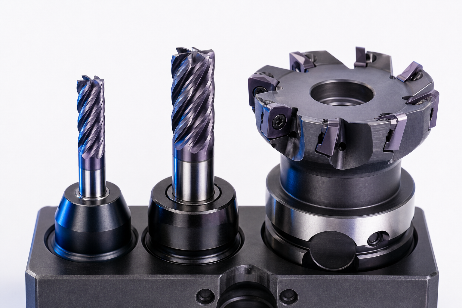
Because RPM = (1000 × Vc) / (π × D), a larger tool requires fewer revolutions to achieve the same peripheral speed. A 3 mm tool at 30 m/min spins at roughly 3,183 RPM — a 25 mm tool at the same cutting speed only needs 382 RPM.
This means there is no single "titanium RPM" — the correct RPM is always derived from the cutting speed appropriate to your operation and the actual tool diameter.
Understand why surface speed, not RPM, is the fundamental parameter in machining.
06Does Titanium Grade Affect Machining Parameters?
Yes. Different titanium grades have different strength, hardness and ductility — which change the cutting forces, heat generation and optimal parameters.
Overview of titanium machinability, alloy properties and process considerations.
07Choosing Cutting Tools for Titanium CNC Machining
The right tool selection is as important as the right speed. Tool material, coating, geometry and stickout directly affect which parameters are safe to use.
Tool Material
Solid carbide (WC-Co) is the standard for titanium end milling. HSS is not recommended for production titanium machining due to excessive wear rates at titanium's cutting temperatures.
Coating
AlTiN (aluminum titanium nitride) and TiAlN are common titanium-machining coatings. They form a protective aluminum-oxide layer at cutting temperature. Avoid TiN — titanium workpiece material can bond to TiN coatings. Always follow the tool manufacturer's coating recommendation for titanium alloys (ISO S material group).
⚙ Flute Geometry
For titanium roughing, fewer flutes (2–4) provide larger flute valleys for chip evacuation. For finishing, more flutes (4–6) can improve surface finish at light engagement. Variable-pitch flutes help reduce chatter in titanium, which is prone to vibration due to its low modulus.
↔ Tool Stickout
Minimize tool stickout (overhang) to maximize rigidity. Every additional diameter of stickout significantly increases deflection and chatter risk. In titanium, where cutting forces are already high, excessive stickout leads to poor finish, dimensional errors and tool breakage.
⌀ Core Thickness
Tools with larger core cross-sections resist deflection better. For titanium, a 4-flute tool with a thick core is often preferred over a 2-flute with thin core when rigidity is the priority — even though chip space is reduced.
Δ Tool Diameter Selection
Larger diameter tools are stiffer and allow deeper cuts, but require lower RPM. Smaller tools can reach tight features but deflect more easily. The diameter should be chosen based on feature geometry, rigidity requirements and the available RPM range of your machine.
08Coolant and Heat Control When Machining Titanium
Because titanium retains heat at the cutting zone, coolant strategy is not optional — it is a core process parameter.

Coolant Delivery Methods
- Flood coolant — minimum requirement for titanium; provides general cooling and chip flushing
- Through-tool coolant — delivers coolant directly to the cutting edge; highly effective for drilling and deep-pocket milling
- High-pressure coolant (70+ bar) — breaks chips and forces coolant into the tool-chip interface; especially valuable for titanium drilling and roughing
Beyond coolant delivery, the following heat-control practices are critical in titanium:
- Avoid recutting chips — clear chips from the cutting zone aggressively
- Avoid rubbing — maintain chip load to keep the tool cutting, not sliding
- Minimize air-cutting and dwell — titanium work-hardens under rub
- Monitor coolant temperature — hot coolant loses effectiveness
09Radial Engagement, Axial Depth & Material Removal Rate
A lower spindle speed does not automatically make titanium machining safer. Poor chip load or excessive tool engagement can still generate excessive heat.
↕ Axial Depth of Cut (ap)
The depth of cut along the tool axis. Deeper cuts remove more material per pass but increase cutting force and heat proportionally. In titanium, the axial depth is often set based on tool supplier data for the specific cutter geometry and coating.
↔ Radial Width of Cut (ae)
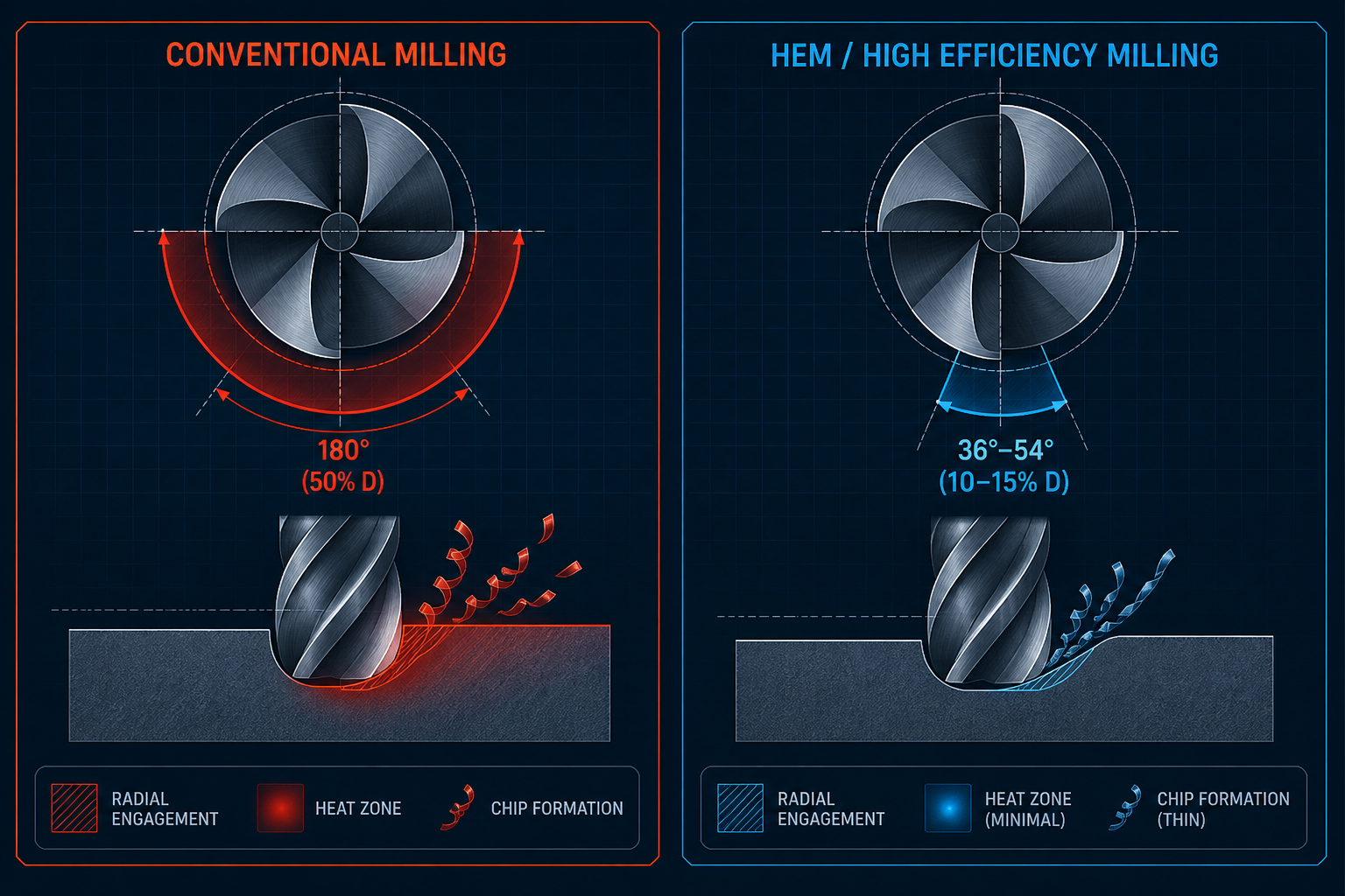
The width of cut as a percentage of tool diameter. This is the single most important parameter for heat management in titanium milling. Reducing radial engagement lowers the tool contact arc, reducing heat input per revolution — this is the core principle of High Efficiency Milling (HEM).
🔥 Tool Engagement Angle
The angular portion of the tool circumference engaged in the cut. Full-width slotting = 180° engagement. HEM strategies typically target 15–30° engagement, dramatically reducing heat per revolution while maintaining productivity through higher axial depth.
⚙ Material Removal Rate (MRR)
MRR = ap × ae × Vf. Titanium MRR is inherently lower than aluminum, but HEM strategies can maintain competitive MRR by trading radial width for axial depth — more steps at lighter width, but deeper per step.
10HEM vs Conventional Milling for Titanium
Titanium productivity often comes from controlling tool engagement and heat, not simply increasing RPM. High Efficiency Milling (HEM) and High Removal Efficient Milling (HREM) use different engagement strategies than conventional approaches.
Conventional Milling
50–100%Radial engagement (ae/DoC ratio). Wide tool contact arc concentrates heat on the cutting edge for a long portion of each revolution. Higher cutting forces per flute. Chip thinning is minimal — feed per tooth stays close to programmed value. Suitable for slotting and when adaptive toolpaths are not available.
HEM / HREM
10–25%Radial engagement (ae/DoC ratio). Small contact arc reduces heat per revolution. Tool spends most of each revolution in air, allowing cooling. Chip thinning effect means programmed feed per tooth must be adjusted upward to maintain desired chip thickness. Enables higher axial depth and sometimes higher cutting speed. Requires CAM support for adaptive/dynamic toolpaths.
Key Takeaway for Titanium
When the same tool is used, switching from conventional wide-engagement milling to HEM with controlled radial engagement can significantly improve tool life in titanium — even at the same cutting speed. The improvement comes from reduced heat per revolution, not from changing RPM.
Public case data from tool manufacturers (e.g. Harvey Performance HREM titanium tests) demonstrates that HEM strategies can increase tool life by 2–3x compared to conventional milling at equivalent MRR in Ti-6Al-4V.
11Signs Your Titanium Cutting Parameters Are Too Aggressive
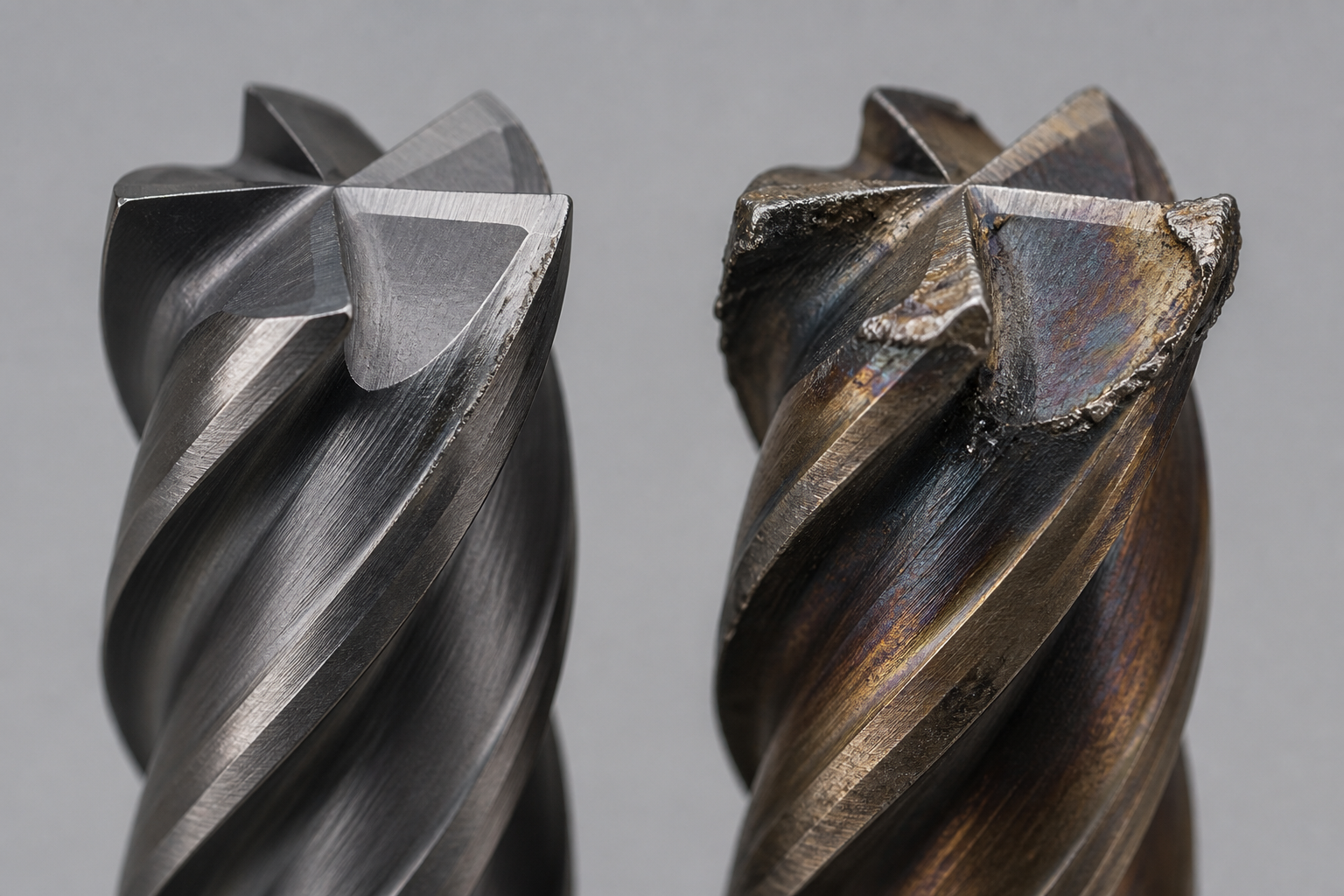
Parameter correction should be based on the actual failure mode rather than simply reducing RPM. Different symptoms point to different root causes.
Identify the Failure Mode First
Simply lowering RPM may address overheating but can worsen rubbing and built-up edge if feed per tooth is not simultaneously adjusted. Correct parameter adjustment requires matching the fix to the specific wear pattern observed.
12RPM Examples at Different Tool Diameters
These examples use a cutting speed of 30 m/min to demonstrate the RPM calculation. The actual cutting speed for your operation must come from your tool supplier's data.
Applied Formula
The examples above demonstrate the calculation only. They are not universal production settings.
13How to Validate Titanium Cutting Parameters
Published cutting data should be treated as starting values, not final settings. Validation requires three levels of evidence.
Manufacturer Data
Tool supplier catalogs, online parameter calculators (e.g. Sandvik Coromant, Seco, Kennametal) and technical datasheets provide cutting speed, feed per tooth and depth-of-cut recommendations for specific cutter geometries, coatings and material groups. These are the primary reference.
Calculated Values
RPM conversion, feed rate calculation and MRR estimation are mathematical operations on manufacturer-supplied inputs. They do not introduce new empirical data — they adapt the supplier values to your specific tool diameter, flute count and machine setup.
Shop-Floor Validation
Start at conservative values (lower end of supplier range). Monitor tool wear pattern, surface finish, chip color and machine sound. Adjust incrementally based on observed results. Document validated parameters for repeat jobs.
Titanium CNC Machining at Goldcattle
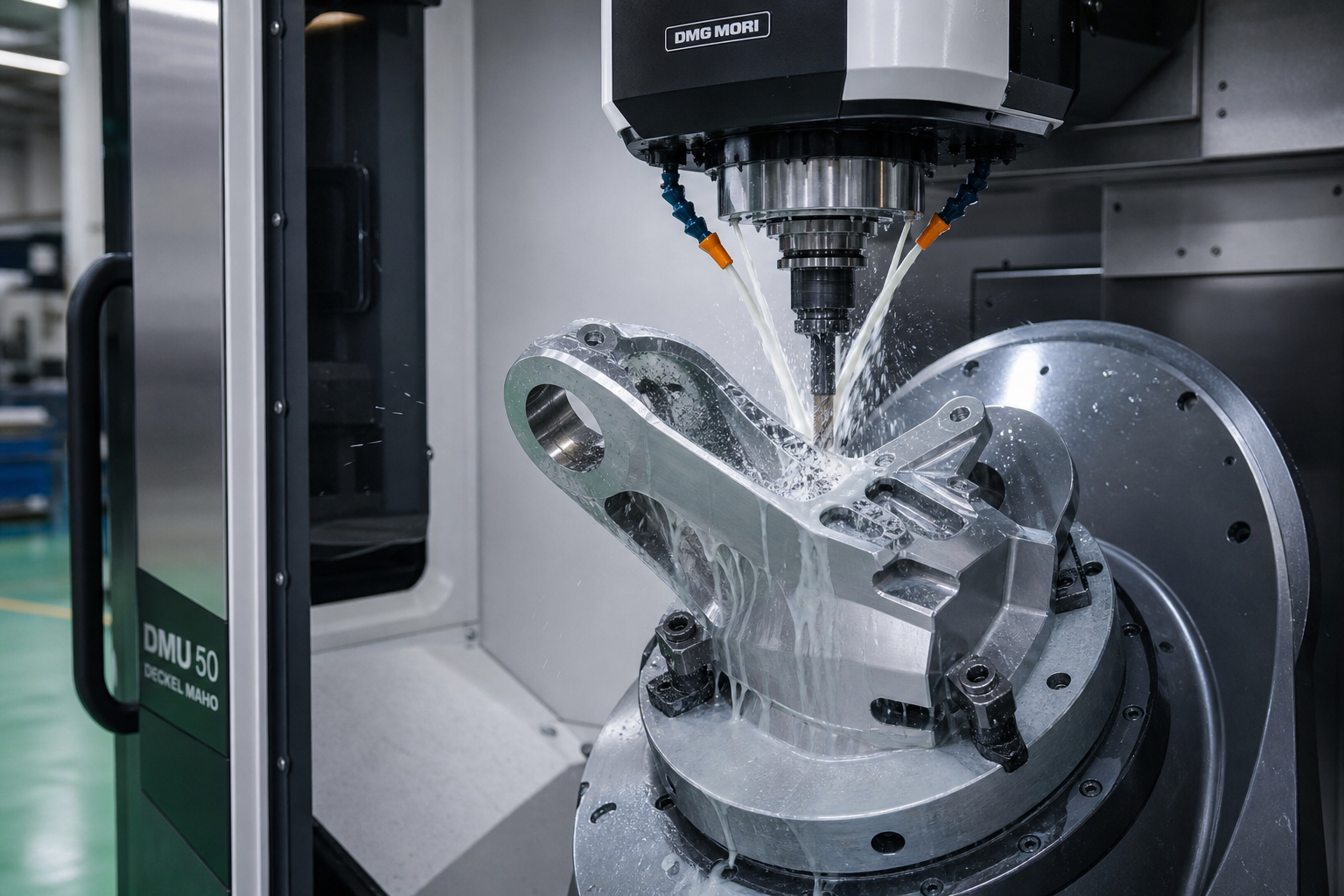
Goldcattle machines Ti-6Al-4V (Grade 5) and other titanium alloys with controlled cutting parameters, appropriate tooling and rigorous inspection.
Engineering-Driven, Not Parameter-Guessed
Every titanium part at Goldcattle is programmed using tool-supplier-validated cutting data, adapted to the specific workpiece geometry, material condition and machine capability. We do not use generic parameter tables — and this guide explains why you should not either.
Full capability overview including 5-axis, turning, milling and inspection.
Design guidelines, tolerances and material options for titanium components.
Precision titanium components with ±0.005 mm capability.
?Frequently Asked Questions
Related Titanium Machining Resources
Understand the relationship between surface speed and spindle RPM.
Machinability, alloy properties and process considerations.