Custom CNC Prototype Parts
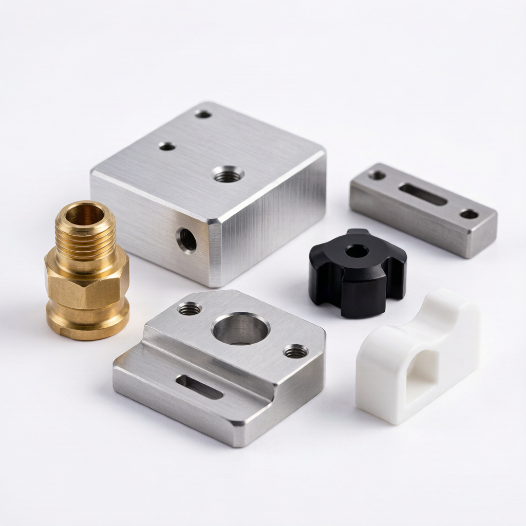
Precision CNC machined prototypes for fit, form and functional testing — from single-piece samples to small pre-production batches, in the materials your production part will actually use.
Accepted files: STEP / STP · IGES / IGS · SAT · X_T · DWG · PDF | *Lead time depends on material, quantity, complexity, tolerance & finishing.
 Prototype → Production
Custom CNC Prototypes for Fit, Form and Functional Testing
When a design moves from screen to hardware, the question is not "can it be machined" — it is "does this part behave the way the model promises?" A CNC prototype lets engineers hold, assemble, load and measure a part made from production-grade material, so validation decisions are based on real mechanical behavior rather than appearance alone.
| Quantity | From 1 piece (single prototype); no fixed minimum batch. |
|---|---|
| Processes | 3-axis, 4-axis and 5-axis CNC milling; CNC turning. |
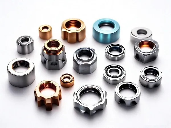
| Materials | Aluminum (6061 / 7075), stainless steel (303 / 304 / 316L), brass, and engineering plastics (POM, PEEK, Nylon, PC, ABS, PTFE, HDPE). |
| Tolerance | ±0.01 mm typical; ±0.005 mm achievable on qualified critical features. Surface finish down to Ra 0.4 μm. |
| Inspection | CMM, micrometers, height gauge and optical inspection per requirement. |
| Finishing | As-machined, anodizing, sandblasting, brushing, polishing, plating, passivation, painting. |
| Prototype lead time | Typically 3–7 business days; project-specific (see Lead Times). |
| Beyond prototype | Small-batch and pilot production supported from the same project. |
| Engineering review | Drawing / CAD review and DFM feedback available before machining. |
*All figures reflect Xiamen Goldcattle's actual capabilities; final values are confirmed per project.
Is CNC Machining Right for Your Prototype?
CNC is rarely the cheapest way to make a visual mock-up — but it is often the strongest way to make a prototype that behaves like a real component. Use the guide below to decide quickly.
| Prototype requirement | How CNC machining fits |
|---|---|
| Need actual production material | Excellent |
| Need tight tolerances | Excellent |
| Need functional testing | Excellent |
| Need threaded holes / features | Excellent |
| Need a metal prototype | Excellent |
| Need good surface finish | Strong |
| Very complex organic geometry | Depends — tool access limits some internal shapes |
| Very cheap visual model only | 3D printing is usually better |
| 100+ identical prototype parts | Evaluate CNC vs. rapid molding |
| Flexible design iterations | Strong |
CNC Machining vs 3D Printing for Prototypes
Both processes belong in a product developer's toolkit. The right one depends on what the prototype must prove.
| Factor | CNC Machining | 3D Printing |
|---|---|---|
| Metal prototype | Excellent | Limited to metal AM processes |
| Production-grade material | Excellent | Depends on process |
| Dimensional accuracy | High | Process-dependent |
| Functional testing | Excellent | Depends on material |
| Threads | Excellent | Often needs post-processing |
| Surface finish | Good – Excellent | Process-dependent |
| Complex internal geometry | Limited by tool access | Excellent |
| Very fast visual mock-up | Less suitable | Excellent |
| One-off cost | Moderate – High | Often lower |
| Design iteration | Good | Excellent |
What Can CNC Prototypes Validate?
A CNC prototype is only useful if it answers the right questions. These are the validations engineers most often run.
Form
External shape, wall structure and overall geometry match the intended design.
Fit
Mating with components, fasteners, brackets, housings and assemblies is verified.
Function
Movement, rotation, sliding, load and operation are tested under real conditions.
Tolerance
Critical dimensions are measured against the drawing to confirm they hold.
Assembly
Screw holes, press fits, snap fits and interfaces are checked during build-up.
Appearance
Shape, texture, anodizing, polishing and color are evaluated where relevant.
Manufacturability
A prototype also reveals whether the design will be sensible to manufacture at scale — tool access, wall thickness, feature sizes and tolerance strategy can all be refined before release.
Prototype Quantities: One-Off, Small Batch and Pre-Production
"Prototype" is not only a single part. The right quantity depends on what stage the project is in.
Single Prototype
Best for initial validation, engineering review and a first fit check before committing to more parts.
Small-Batch Prototypes
Useful for parallel testing, multiple engineers, or several assembly and design iterations at once.
Pre-Production Batch
Supports pilot testing, customer evaluation, field testing and assembly validation ahead of full production.
Quantity ranges reflect typical prototype project patterns; final order size is confirmed per project.
From CNC Prototype to Production
The value of a prototype supplier grows when the same partner can carry the project forward — review, machine, inspect, iterate, then scale.
Prototype Material Selection
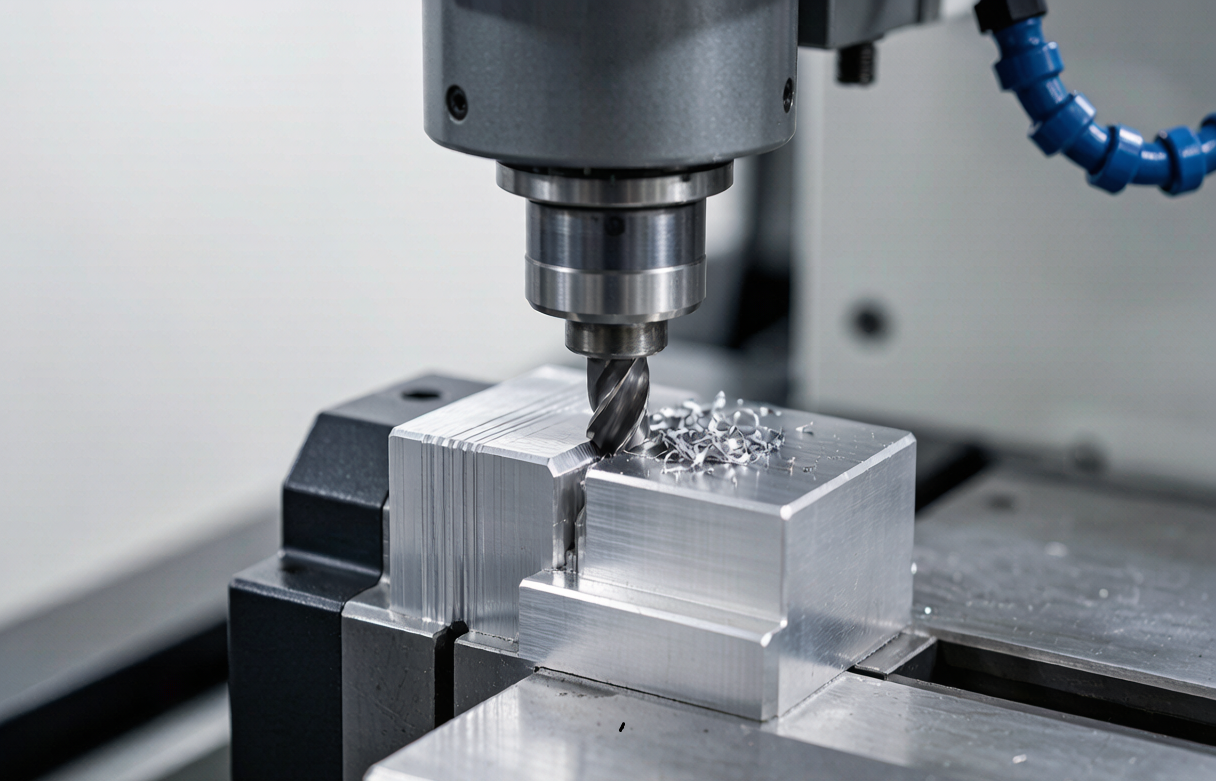
Material choice should follow the test objective. Below are the families most often used for CNC prototypes, and why a developer would pick each.
Aluminum
6061
General prototypes, housings, brackets and structural parts. Easy to machine, good strength-to-weight, and a common production material — so prototype and final part stay consistent.
7075
High-strength, lightweight structures where mechanical load matters more than corrosion resistance.
Stainless Steel
303
Free-machining grade for functional parts where speed matters.
304
General corrosion-resistant prototypes and housings.
316L
Marine, medical or chemical environments needing higher corrosion resistance.
Brass
Brass (C360 / similar)
Electrical components, fittings and functional mechanical parts where machinability and appearance both matter.
Engineering Plastics
POM / Acetal
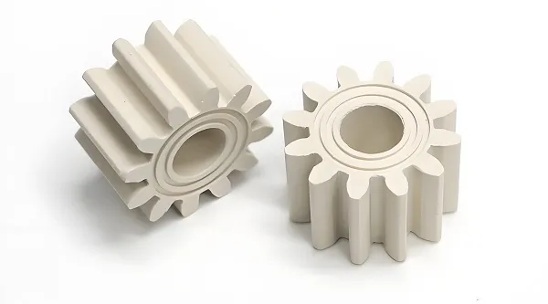
Low-friction, wear-resistant gears, sliders and bushings.
PEEK
High-temperature, chemical-resistant and medical-grade prototypes.
Nylon / PC / ABS
General plastic prototypes; PTFE and HDPE for low-friction or chemical duties.
Should Your Prototype Use the Final Production Material?
A common misconception is that a prototype must always be the final material. The better rule: select the material by what the test must prove.
Use the final material when testing…
- Strength and load behavior
- Heat resistance
- Friction and wear
- Assembly and fit
- Dimensional stability
A substitute may be enough when testing…
- Basic shape and ergonomics
- Early concept form
- Simple visual fit
- Non-critical appearance
CNC Prototype Tolerances and Critical Dimensions
Tolerance strategy matters more than a single number. Over-tolerancing the whole part adds cost and inspection work without improving the result.
General Dimensions
Standard machining tolerance applied to non-critical features — enough for fit and handling.
Critical Dimensions
Tighter bands set where function requires — driven by part size, material, feature geometry, process and inspection method.
Precision Features
Achievable on qualified features such as bearing bores, shaft fits, mounting interfaces, threaded holes and sealing surfaces.
Inspection methods
CMM, micrometers, height gauge and optical inspection are used according to the criticality of the feature and the data the validation plan requires. See the Inspection section for the reports available.
CNC Prototype Design Guidelines
Good prototype geometry machines faster, costs less and validates more reliably. These are the points reviewed during DFM feedback.
- Internal corners CNC tools are round, so allow a sensible internal radius rather than a sharp corner.
- Deep pockets Deep cavities can increase tool deflection, vibration and machining time — keep depth-to-width reasonable.
- Thin walls Thin sections flex, deform or chatter; keep walls thick enough for stable cutting.
- Small holes Very small diameters increase cost and difficulty — use standard drill sizes where possible.
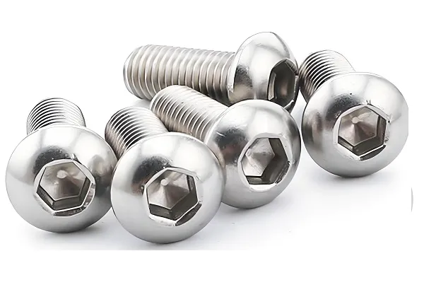
- Threads Confirm thread standard, depth and blind vs. through hole before machining.
- 5-axis features Complex angled surfaces need tool-access planning; 5-axis setups can reduce operations.
How to Make CNC Prototypes Faster and More Cost-Effective
Prototype cost is driven by material, complexity, tolerance, finishing and how complete the drawing is — not by a single "rapid" label.
Use standard materials
Where the final part allows, 6061 aluminum keeps cost and lead time predictable.
Avoid unnecessary tight tolerances
Assign tight bands only to critical dimensions.
Simplify deep pockets
Reasonable depth-to-width reduces machining time and risk.
Use standard hole sizes
Standard drills and taps avoid special tooling.
Reduce complex setups
Design features accessible in fewer operations where function allows.
Send a complete drawing
A clear 3D model + 2D with critical specs shortens review and quote time.
CNC Prototype Surface Finishes
Whether a prototype needs finishing depends on the validation goal. If appearance, corrosion or final assembly behavior is part of the test, specify the finish up front.
As-Machined
Standard mill finish; fastest option for pure fit/function checks.
Anodizing
Corrosion resistance and color for aluminum prototypes.
Sandblasting
Uniform matte texture.
Brushing
Directional satin finish.
Polishing
Smooth, reflective surfaces where needed.
Plating
Functional or decorative metal coatings.
Painting
Color matching and protective coating.
Passivation
Corrosion protection for stainless steel.
Finish availability depends on material and process compatibility; confirm per project.
CNC Prototype Lead Times
Speed comes from a digital CAD workflow, fast engineering review, material availability, machine scheduling, streamlined inspection and express finishing — not from a fixed "1-day" promise that may not fit your part.
Typical stage breakdown
| Stage | Typical time |
|---|---|
| CAD / Drawing review | Within 1 business day |
| DFM feedback | Within 1–2 business days |
| Quotation | Within 1 business day of review |
| Machining | 2–5 business days (project-dependent) |
| Inspection | 0.5–1 business day |
| Finishing | 1–4 business days if required |
| Shipping | Per carrier / Incoterms |
Lead time by project type
| Project | Typical lead time* |
|---|---|
| Simple aluminum prototype | 5–8 business days |
| Complex 5-axis prototype | 8–14 business days |
| Plastic (engineering) prototype | 4–7 business days |
| CNC turning prototype | 4–7 business days |
| Prototype + anodizing | 7–11 business days |
*Ranges reflect typical projects; actual lead time depends on material, quantity, complexity, tolerances, finishing and inspection requirements.
CNC Prototype Inspection and Quality Control
A prototype is still an engineered part — inspection is not "optional because it is a sample." The level of inspection follows the validation plan.
First Article Inspection
Key features checked on the first part of the run.
Dimensional Inspection
Critical and general dimensions measured against the drawing.
Critical Feature Check
Bores, fits, threads and sealing surfaces verified where function depends on them.
Thread / Fit Check
Functional verification of assembled interfaces.
Surface Inspection
Finish, marks and appearance reviewed per requirement.
Material Verification
Material certificate available where specified.
What inspection data can you receive?
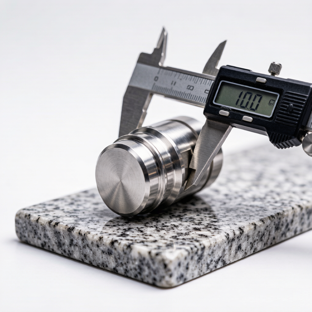
- Dimensional inspection report — measured values vs. drawing
- Critical dimension results — focused on CTQ features
- Material certificate — where specified
- Shipment photos — before dispatch
- CMM report — for complex geometry where applicable
- Surface inspection record — finish and appearance
Report types are provided according to the actual inspection scope agreed for the project.
Prototype vs Production CNC Parts
Understanding the difference helps set the right expectations — and the right budget — at the prototype stage.
| Factor | Prototype | Production |
|---|---|---|
| Main goal | Validation | Repeatability |
| Quantity | Low | Medium / High |
| Design | May change | Released |
| Tolerance | Functional | Production standard |
| Finish | Evaluation-specific | Final specification |
| Process | Flexible | Optimized |
| Tooling | Often unnecessary | May be required |
| Cost per part | Higher | Lower at scale |
CNC Prototype vs Rapid Injection Molding
For polymer parts, the alternative to CNC is often rapid tooling. Each fits a different point in the development timeline.
| Requirement | CNC Prototype | Rapid Injection Molding |
|---|---|---|
| 1–10 parts | Excellent | Often inefficient |
| Need production material | Excellent | Excellent |
| Complex molded geometry | Limited | Excellent |
| Design changes | Easy | Mold modification |
| High initial tooling cost | Low | Higher |
| Final molding validation | Limited | Excellent |
| Early mechanical validation | Excellent | Excellent |
Custom CNC Prototype Case Studies
Generic capability showcases — structured the way engineers evaluate a supplier: material, process, quantity, purpose, challenge and result.
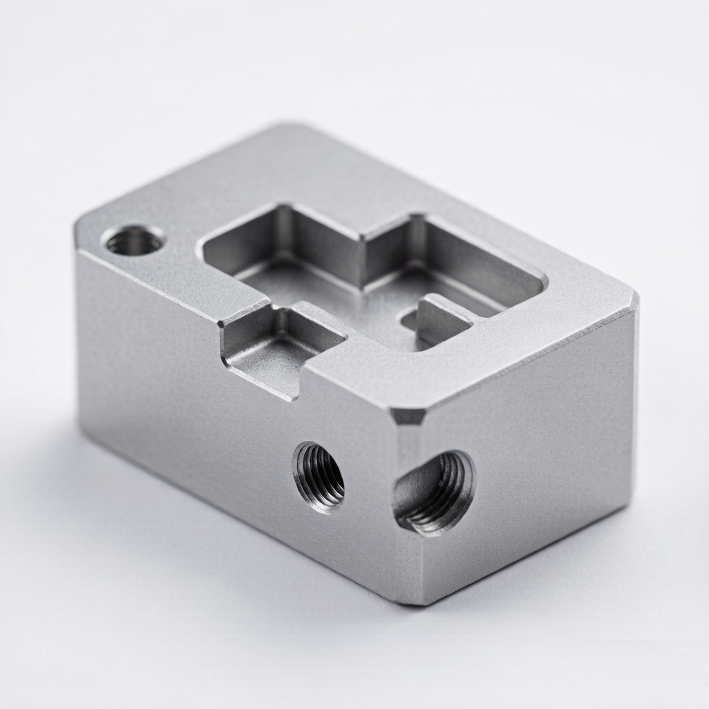
6061 Aluminum Housing
Challenge: Tight mounting interface needed to seat against a mating part.
Result: Passed assembly validation; tolerance held on critical bores.
5-Axis Aluminum Component
Challenge: Multiple angled surfaces difficult in fewer setups.
Result: 5-axis machining reduced setups; CMM confirmed features.
Stainless Bracket Prototype
Challenge: Threaded holes had to align across an assembly.
Result: Thread and fit verified; cleared for pilot batch.
What Do We Need for Your Prototype Quote?
A complete package shortens review and quote time. The most useful fields to include:
Files & specs
- 3D CAD file — STEP / STP, IGES / IGS, SAT or X_T
- 2D drawing — DWG or PDF with critical dimensions
- Part name and a short description
- Required tolerance — especially CTQ features
- Surface finish requirement
Project context
- Prototype quantity
- Material preference (or "advise")
- Testing requirement — what must the part prove
- Target delivery date
- Expected production volume after prototype — helps us recommend process and scale path
CNC Prototype Parts: Quick Answers
Concise answers to the questions engineers ask most often when sourcing a CNC prototype.
Frequently Asked Questions
What is the minimum order quantity for a CNC prototype?
The minimum is typically 1 piece for a single prototype. Small batches of 5–50 pcs and pilot batches are also supported; the right quantity follows the validation stage.
How fast can I get a CNC prototype?
Prototype lead time is typically 3–7 business days, extending with complexity, 5-axis work, tight tolerances, finishing and inspection. Actual time is confirmed per project.
Which materials can you prototype in?
Aluminum (6061 / 7075), stainless steel (303 / 304 / 316L), brass, and engineering plastics including POM, PEEK, Nylon, PC, ABS, PTFE and HDPE.
What tolerance can CNC prototypes achieve?
Typical machining tolerance is ±0.01 mm, with ±0.005 mm achievable on qualified critical features such as bores, fits and sealing surfaces. Surface finish down to Ra 0.4 μm is possible.
Should my prototype use the final production material?
When the test must prove strength, heat, friction, wear, assembly or dimensional behavior — yes. For early shape or concept checks, a suitable substitute may be enough. Material should follow the test objective.
Can you anodize or plate a prototype?
Yes, where compatible with the material and process. Anodizing, sandblasting, brushing, polishing, plating, painting and passivation are options; specify finishing in the RFQ if it is part of the validation plan.
Do you provide inspection reports?
Yes. Depending on the agreed scope, dimensional inspection reports, critical-dimension results, material certificates, shipment photos and CMM reports can be provided.
Can you help review my design before machining?
Engineering review and DFM feedback can be provided before machining to reduce risk and improve manufacturability.
What CAD file formats do you accept?
STEP / STP, IGES / IGS, SAT, X_T and common native formats, plus DWG / PDF 2D drawings where critical dimensions are defined.
Can a prototype lead to production?
Yes — the same project can move from prototype through pilot batch to production, provided capacity and process are confirmed for each stage.
Is CNC or 3D printing better for my prototype?
Use CNC when the prototype must validate real material, tolerance and function. Use 3D printing for fastest, lowest-cost visual or geometrically complex concept models.
How should I specify tolerances on a prototype drawing?
Apply standard tolerance to general features and assign tight tolerances only to Critical-to-Function dimensions. This keeps cost and inspection focused where it matters.
Request Custom CNC Prototype Parts
Send your CAD file and prototype requirement. We review feasibility, provide DFM feedback and quote a realistic, project-specific lead time.