Electronics Enclosure Injection Molding
PCB-centric enclosures in ABS, PC, PC/ABS and FR grades — designed for fit, sealing, shielding and volume, then molded and assembled under one roof.
An electronics enclosure is not a box with a lid. It is the mechanical system that holds your PCB, protects it from impact, dust, water and interference, sheds heat, and presents your product to the user. This page explains how injection-molded enclosures are designed and built — boss geometry, snap-fits, tolerances, materials, flame retardancy, IP and EMI options, thermal paths, tooling and cost — and where Xiamen Goldcattle's integrated molding and machining capability fits electronics housing programs.
Quick Answer: What Is Electronics Enclosure Injection Molding?
Injection molding is the standard way to produce plastic electronic housings at consistent quality and low piece cost. The enclosure is engineered around the PCB and molded in steel tooling — here are the eight points that decide whether it is right for your program.
8 Points That Define a Molded Electronics Enclosure
Use these to scope your project before requesting a quote.
- PCB-first geometryBosses, standoffs and cutouts are placed from the board, not the outer shell.
- Uniform wall stock1.5–2.5 mm nominal, even thickness to avoid sink and warp.
- Integral fasteningScrew bosses and snap-fits replace loose hardware where possible.
- Material by dutyABS / PC / PC-ABS / PA, with FR grades for flammability targets.
- Sealing featuresGasket grooves, tongue-and-groove, welding or bonded seals for IP.
- Shielding optionsConductive coatings, platings, shielded sub-assemblies for EMI.
- Thermal pathVents, fins, conductive pads and sink contact sized to the heat load.
- Tooled for volumePrototype tool then hardened steel mold as volume justifies cost.
What Is Electronics Enclosure Injection Molding?
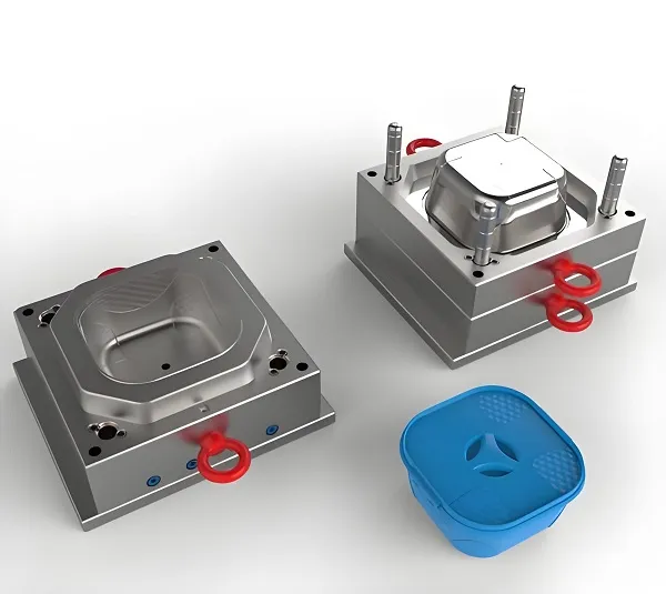
Injection molding produces a plastic housing by injecting molten resin into a machined steel cavity, cooling it, and ejecting a rigid, repeatable part. For electronics, the part is a system: it must locate and protect a PCB while meeting cosmetic, environmental and regulatory needs.
The Mold Makes the Part
A precision steel tool defines every wall, boss, rib, snap and surface. Tool quality sets the ceiling on dimensional repeatability and cosmetic finish across the whole production run.
Repeatability at Volume
Once the tool is qualified, every shot is near-identical. That is why molding beats CNC or 3D printing on unit cost and consistency from the low thousands upward.
Features Built In
Bosses, clips, hinges, labels, texture and sealing grooves are molded in one cycle — no secondary routing, less assembly, fewer loose parts.
Why Choose Injection Molding for Electronic Enclosures?
Molding is not always the answer. The right process depends on volume, lead time, wall geometry and cosmetic needs. Use the comparison below to decide, and see the dedicated process comparison for a fuller view.
| Process | Best for | Typical volume | Tooling cost | Lead time |
|---|---|---|---|---|
| Injection molding | Repeat housings, integrated features, cosmetics | Hundreds → millions | Medium–High | Tool first, then fast |
| CNC from stock | Prototypes, low volume, metal or tight tolerance | 1 – few hundred | None | 3–7 days |
| 3D printing | Concept proof, complex voids, no tool | 1 – low tens | None | 1–3 days |
| Die casting | EMI/heat-critical metal shells | Hundreds → high | High | Tool first |
| Sheet metal | Large, ventilated, grounded boxes | Tens → high | Low–Med | Fast–Med |
- Pick molding when annual volume clears the tooling cost and you want integrated features + cosmetics.
- Keep CNC and 3D printing for prototypes and spares; see CNC Machining Services and 3D Printing Services.
- Molding and machining are complementary: we often mold the shell and CNC the inserts, jigs and fixtures.
Start With the PCB, Not the Box
The single biggest cause of rework is designing the outer shell first, then discovering the PCB will not fit, the connector pokes through the wrong face, or the boss pattern mismatches the board. Design the housing geometry from the PCB outline.
Locate from the board
Place screw bosses on the PCB mounting holes, set standoffs to the tallest component under each zone, and keep clearance above connectors, LEDs, switches and test points.
Orient the interfaces
Decide which face carries the connector, button, display and antenna before the shell is shaped, so cutouts land where the user and cable expect them.
Control the stack-up
Cover height = PCB thickness + component standoff + lid sealing/clearance. Tolerances on each layer add up — design the fit, don't hope for it.
Mark the parting line
Put the mold split where it hides from view and away from sealing and cosmetic surfaces; this is decided together with the PCB envelope.
A PCB outline in DXF or STEP (even a preliminary one), the connector and component keep-out zones, and the target stack height. We return a housing concept built around that board — not a generic box with holes added later.
DFM Rules for Enclosure Molding
Good DFM is what keeps a molded enclosure from sinking, warping, short-shooting or binding at assembly. These rules apply before the tool is cut.
- Uniform wall Keep nominal wall even; avoid sudden thick sections that sink.
- Draft on every wall 0.5°–1.5° per side so the part ejects cleanly.
- Ribs, not thick walls Stiffen with ribs; keep rib thickness ~0.5–0.6× wall.
- Bosses hollow Core the center to stop sink; gusset to the wall.
- Generous fillets Round internal corners to ease flow and reduce stress.
- Avoid undercuts Or plan slides/lifters and accept the tool cost.
- Gate away from cosmetics Place the gate where its mark will not show.
- Texture hides flaws Light texture reads better than gloss on big flat faces.
- Thick boss bases to "add strength" — they sink and warp. Use a cored boss + rib instead.
- Zero draft on side walls "to save space" — the part locks in the tool and scars on ejection.
Wall Thickness & Uniformity
Wall thickness drives strength, cycle time, sink and warpage. The goal is not "as thin as possible" but "as uniform as possible."
Nominal 1.5–2.5 mm
Typical enclosure
Covers most small–medium housings in ABS/PC/PC-ABS with good fill and few sink risks.
1.0–1.2 mm
Thin-wall
Possible for small parts in high-flow resin; needs careful gate, vent and process window.
>3 mm
Avoid
Invites sink, voids and long cooling; stiffen with ribs instead of thick walls.
Screw Bosses & Standoffs
Bosses locate and fasten the PCB and the cover. Done wrong they sink, crack or misalign the board. Done right they are the quiet hero of a clean enclosure.
Size by screw
Outside diameter ≈ 2× the screw major diameter; wall thickness of the boss ≈ 0.6–0.7× the nominal wall. Too thin cracks, too thick sinks.
Hollow the core
A cored center (with a short blind bottom) prevents sink on the outer face. Add a fillet at the base to the wall.
Gusset to the wall
Connect the boss to the side wall with ribs so it cannot flex or warp during molding and tightening.
Match the PCB
Place bosses on the board's mounting holes so the PCB, boss and cover line up in one stack — no shims, no twist.
- Self-tapping screw into a cored boss: low cost, fine for covers and non-cyclic loads.
- Molded-in brass insert: for repeated disassembly, higher torque, or metal-to-plastic threads. We support ultrasonic and heat-press insertion.
Snap-Fits, Living Hinges & Clip Features
Integral snap features cut screw count and assembly time — but they must be engineered for the resin's flex and the number of open/close cycles you expect.
Cantilever snaps
Common lid catch
Size deflection to the resin strain limit; keep under ~2–3% strain for permanent snap, more only for flexible TPE.
Living hinge
PP / PE
One-piece hinge in polypropylene; not suited to ABS/PC. Use only where the resin supports it.
Torsion & bayonet
Rotary lock
For covers that must rotate or twist-lock; needs careful draft and release angle.
- Snap-fits fatigue. If the cover is opened often or loaded, use screws on at least two corners and snaps elsewhere.
- Brittle resins (some FR grades) snap rather than flex — choose the clip geometry to the material.
Parting Line, Draft & Ejection
The way the tool splits decides where the visible seam lands and whether the part releases. These are set in the CAD, not after molding.
- Parting line Hide it on a edge or feature line; keep it off sealing and cosmetic faces.
- Draft angle 0.5°–1.5° on every wall that runs parallel to ejection; texture needs more.
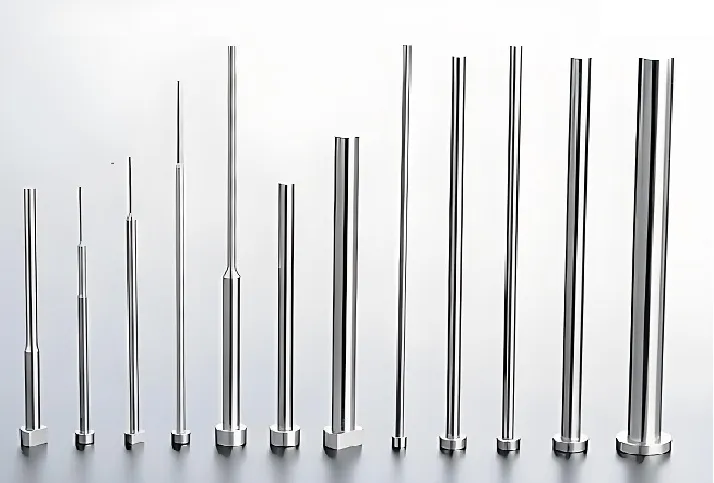
- Ejector pins Land on flat, non-cosmetic areas; we place them to avoid read-through.
- Slides & lifters Required for undercuts (side clips, internal threads); add tool cost.
- Vents At the last-fill area and near deep ribs to prevent short shots and burn.
- Shut-offs Designed so the two cavity halves seal without flashing.
Tolerances, Fit & Sealing Surfaces
One tolerance for the whole part is wrong. Set tight tolerances only where fit matters, and leave the rest loose — that is what makes the enclosure assemble first time.
| Feature | Typical molded tolerance | How we control it |
|---|---|---|
| Boss ID (screw) | ±0.05–0.10 mm | Tight — core pin, CMM check |
| Snap / clip engage | ±0.10 mm | Tight — gage fit at FA |
| Sealing face flat | ±0.08–0.12 mm | Tight — flatness gage |
| Overall size | ±0.15–0.25 mm | Loose — process window |
| Non-critical wall | ±0.20–0.30 mm | Loose — sink allowance |
- CMM first-article report on critical features; in-process checks on the sealing and boss zones.
- Shrinkage is compensated in the tool, not by hoping the resin behaves — we set the mold steel size from the resin's shrink rate.
Material Selection for Electronics Housings
Material choice sets impact resistance, heat performance, chemical resistance, cosmetics and cost. Pick by duty, not by habit.
| Resin | Strengths | Watch-outs | Typical use |
|---|---|---|---|
| ABS | Low cost, easy mold, good surface | Moderate heat, UV yellows | Indoor consumer, adapters |
| PC | High impact, heat, clarity | Cost, prone to flow marks | Rugged, transparent windows |
| PC/ABS | Impact + process balance | — | General electronics, FR grades |
| PA (Nylon) | Heat, chemical, wear | Absorbs moisture → grow | Industrial, connectors |
| PBT | Heat, electrical, dims stable | Notch sensitive | Connectors, under-hood |
| FR grades | Flame retardant (PC/ABS FR) | More brittle, cost | Regulated enclosures |
- See the full Materials index, or Custom ABS Plastic Molding and Custom Acetal Parts for material-specific pages.
- Tell us the temperature, chemical and regulatory duty; we propose a grade and a backup.
Flame Retardancy & UL 94
Many electronics programs need a flammability class. We can mold to a stated resin flammability rating — but final product compliance is a tested certification, not a mold claim.
We mold flame-retardant resin grades (for example PC/ABS FR, ABS FR) and meet the flammability class stated on the resin supplier's certificate. We select a grade that supports your target class (e.g., V-0 / V-2 at a given thickness).
- We do not self-declare "UL 94 compliant enclosure" without the part being tested — wall thickness and design change the result.
- Full product Listing (UL, CSA, etc.) is a separate certification step you run on the finished assembly.
IP / Weather Protection
A water- or dust-tight enclosure is a system: molded geometry, gasket, compression and assembly together decide the rating. We build the features; the rating is proven by test.
Gasket groove
Compression seal
A controlled groove seats a bonded or placed gasket; compression is set by boss length and lid fit.
Tongue & groove
Labyrinth
A molded interlock blocks direct water path without a gasket for light duty.
Ultrasonic weld
Permanent seal
Welds two halves into a sealed joint — good for sealed, non-serviceable units.
Cable glands
Entry seal
Molded or bought glands keep the rating at wire entries.
- We design and mold the sealing geometry that supports an IP rating; the achieved rating depends on gasket, assembly and the complete device, and must be confirmed by an independent ingress test.
- We do not print "IP67" on a part we have not tested to IP67.
EMI / RFI Shielding
Plastic does not shield. If your device must contain or reject interference, the enclosure must carry a conductive path — built as an option, not assumed.
Conductive coating
Spray / plate
Nickel or copper coating on the inner wall; needs a continuous conductive path to ground.
Plated inserts
Metal frame
A stamped metal shield or bezel molded or pressed in; best for apertures.
Shielded sub-assembly
Can-in-can
A conductive inner can around the noisy section, inside the plastic shell.
Conductive gasket
Seam seal
EMI gasket at the lid seam maintains the shield across the split.
- Shielding effectiveness must be measured for your frequency band and required attenuation — it is not a property of "a metalized box."
- We build the geometry, mounting and ground features; you specify the target dB and band, and we propose a moldable approach with a shielding partner if needed.
Thermal Management
Plastic insulates. If your PCB makes heat, the enclosure must move it — by convection, conduction or radiation — or the device throttles and ages.
Vents & louvers
Passive convection for low heat loads; size and place to keep IP rating if needed (a labyrinth, not an open hole).
Fins & ribs
Molded external fins raise surface area; internal ribs can channel airflow.
Conduction to sink
A boss or pad presses the hot component to an external metal sink or the enclosure wall; plan flatness and pressure.
Material choice
PC/ABS and filled grades conduct and survive heat better than ABS for warm electronics.
Surface Finish & Aesthetics
Finish is specified on the tool, not added later. It sets cost, scratch visibility and brand feel.
- Polished / gloss Sharp look; shows sink, flow and scratches.
- VDI texture Hides flaws; standard for large faces.
- Soft-touch Via overmold TPE; premium feel, more cost.
- Color match Pantone / RAL; keep gloss consistent across parts.
- Print / laser Pad, UV or laser marking for logos and labels.
- Light pipes Clear PC light guides molded into the wall.
- Texture and gloss are cut into the steel — changing them means re-working the tool.
- Two-shot or overmold gives a permanent soft-touch or sealed color; see Overmolding.
Overmolding & Two-Shot Molding
Bonding a soft material to a rigid shell in one process gives gaskets, grips, buttons and waterproof seals without assembly.
Soft gasket
A TPE/TPU lip molded onto the lid forms the seal in place — no loose gasket to misplace.
Soft-touch grip
Overmolded TPE on a handle or edge for ergonomics and brand feel.
Sealed buttons
Flexible boot over a switch, molded as one part.
Prototype vs Production Tooling
You do not need a hardened steel mold on day one. Match the tool to volume and risk.
| Tool type | Best for | Lead time | Cost |
|---|---|---|---|
| CNC prototype | Fit check, photos, 1–tens | 3–7 days | Low |
| Aluminium / soft steel | Low volume, design not locked | Weeks | Medium |
| Hardened steel | Locked design, volume | Weeks | Higher |
| Multi-cavity | High volume, low piece cost | Longer | Highest |
Prototype in CNC or a soft tool to validate fit and DFM, then move to hardened steel once the design is fixed. We keep the part definition so the production mold matches the approved prototype.
Gate, Runner & Cosmetic Considerations
Where the melt enters decides fill, weld lines, sink and the visible gate mark. This is planned with the part shape.
- Edge gate Simple, cheap; leaves a mark to trim on a non-cosmetic edge.
- Submarine gate Auto-trims; good for cosmetic faces, slight vestige.
- Pin / hot tip Small mark; for small parts and hot-runner tools.
- Weld lines Avoid landing them on sealing or strength features.
- Pack & hold Set to kill sink without over-packing the wall.
- Cooling balance Even cooling = less warp; designed into the tool.
Process Control & Warpage Prevention
A good tool can still warp if the process is wrong. Warpage comes from uneven shrinkage — caused by wall imbalance, poor cooling or wrong pack.
Balance the wall
Even thickness → even shrink → flat part. The #1 warp fix is in the CAD, not the press.
Symmetric cooling
Mirror-image cooling lines keep both halves shrinking together.
Correct pack
Enough to fill, not so much the wall stresses. Set from a short-shot study.
Material dry
PA/PBT absorb water; dry before molding or they splay and weaken.
- First-article CMM on flatness and boss pattern; process window documented and locked for the run.
- If a flatness spec is critical (sealing face), we gage it at FA and on a cadence in production.
Quality, Inspection & First Articles
Enclosures are judged on fit and appearance, not just a dimension. Our inspection covers both.
First Article (FA)
Per tool
CMM + visual + fit check on the approved first shots before volume runs.
In-process
Cadence
Critical features (boss, seal face) checked on a schedule during the run.
Visual
Cosmetic
Gate vestige, flow marks, texture and color against the signed standard.
Fit test
Assembly
PCB and cover mated on a gauge or real board to confirm stack-up.
Color, Branding & Logos
Color and marks are part of the product. Specify them with the tool, and keep them consistent across a run.
- Pantone / RAL Match to a standard; allow a small batch-to-batch delta.
- Masterbatch Pre-colored resin for uniform body color.
- Pad / UV print Logos and labels on flat areas.
- Laser engrave Permanent mark, no ink; good for serials.
- Insert molding Metal badge or lens molded in place.
- Two-shot color Permanent two-tone without paint.
Assembly & Secondary Operations
An enclosure often ships as more than a shell. We can deliver a partially or fully assembled unit.
Molded-in inserts
Brass/steel threads via ultrasonic or heat press, molded in or pressed after.
PCB install
Board seated on bosses, screwed or clipped, with standoff clearance checked.
Gasket & seal
Gasket placed or bonded, lid closed and torqued to the seal spec.
Label & kit
Printing, labeling, barcode, and packed kit with screws and docs.
- Send the assembly steps you want us to own; we quote them as a line, not as a surprise.
- Machining and molding under one roof means jigs and fixtures are made in-house — see CNC Machining Services.
Volumes, MOQ & Lead Times
We support the full arc from a single prototype to repeat production on the same part definition.
Cost Drivers for Enclosure Molding
Quote the tool and the piece price separately — that is the only way to see what you are paying for.
- The lowest piece price can hide a weak tool that warps or a resin downgrade that fails FR — compare total landed cost and risk, not unit price.
- We separate tooling from piece price so you can choose prototype-now / harden-later.
Common Enclosure Design Mistakes
Most enclosure rework traces to a short list of avoidable errors. Check yours before tooling.
- Shell-first design Board added late → bosses mismatch, connector wrong face.
- Thick boss bases Added "for strength" → sink and warp.
- Zero draft Side walls bind in the tool and scar on ejection.
- One global tolerance Tight everywhere → tool fights the resin.
- Gate on a face Visible mark because placement was not planned.
- FR resin, no test "Compliant" claimed without part certification.
- IP by hope No gasket groove, then "make it waterproof."
- Snap for everything Brittle FR grade + frequent open → clip breaks.
Before steel is cut, we return a written DFM note on wall, boss, draft, gate, tolerance and any IP/EMI/FR gap — so the tool is right the first time.
Xiamen Goldcattle's Electronics Enclosure Capability
One integrated manufacturer for the shell and the parts around it — molding, machining, tooling, 3D printing and sheet metal under one roof, with in-house inspection.
Six processes, one roof
Integrated
CNC precision machining, injection molding, mold making, 3D printing, die casting, sheet metal/stamping.
Enclosure molding
ABS / PC / PC-ABS / PA / PBT / FR
Bosses, snap-fits, overmold, texture, color; prototype to production tooling.
Machining support
3 / 4 / 5-axis
Inserts, jigs, fixtures and mating metal parts made in-house.
Inspection
CMM-verified
Typical ±0.01 mm, tight ±0.005 mm on qualified features, Ra 0.4 μm.
Certifications
ISO 9001:2015
Plus SGS (SZIN2409001808ML09_EN), RoHS (TQT7737B1373EC), Rmbond (XMML24030283_EN).
Lead times
3–7 / 7–20 / 15–25 wd
Prototype / low-volume / mass production, industry mid-to-upper band.
Injection Molding vs Other Processes — When to Choose What
Use this to pick the right build for your stage and volume. None of these is "best" — only best-fit.
| If you need… | Choose | Why |
|---|---|---|
| 1–50 housings fast | CNC or 3D print | No tool; days, not weeks |
| Thousands, integrated features | Injection mold | Low piece cost, consistent |
| EMI shield + heat sink | Metal die cast / sheet | Conductive by nature |
| Tight metal tolerance part | CNC machining | ±0.01 mm, no tool |
| Complex internal voids | 3D printing | Geometry freedom, no tool |
- Custom Plastic Components · Custom Plastic Injection Mold
- Custom Rotational Molding · Stainless Steel CNC Machining
- Note: CNC plastic machining and custom electronics enclosure pages are planned; until live they are text-only references here.
Frequently Asked Questions
What is electronics enclosure injection molding?
What materials are best for electronic enclosures?
Can you mold an enclosure designed around my PCB?
How do you design screw bosses for plastic enclosures?
What wall thickness should an injection-molded enclosure have?
Can you achieve an IP rating on a molded enclosure?
Do you provide EMI/RFI shielding for enclosures?
Are your enclosures flame retardant or UL 94 compliant?
How do you control tolerances and fit between housing halves?
What is the minimum order quantity for enclosure molding?
How long does it take to make an enclosure mold and parts?
Should I choose prototype or production tooling?
Can you do overmolding or two-shot molding for seals and grips?
How much does an electronics enclosure mold cost?
Do you handle inserts, assembly and labeling?
How do I request a quote for an electronics enclosure?
Request an Electronics Enclosure Quote
Send your 3D model, the PCB outline if you have it, material and any IP/EMI/FR target. Our engineering team will return a DFM review and a quote covering tooling and piece price — whether you are validating a prototype or ready for volume.