Custom CNC Machined Jigs & Fixtures for Repeatable Workholding
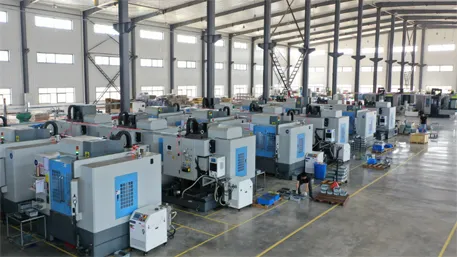
Xiamen Goldcattle machines fixture plates, locator components, drill jigs, assembly nests, inspection fixtures and soft jaws to your engineering drawings. Our CNC milling, drilling, tapping, turning, EDM and grinding routes produce the datum faces, pin holes, clamp interfaces and wear contacts a fixture needs, with dimensional inspection on the CMM. This page describes drawing-based custom workholding: what we make, how locating and clamping are handled, what materials and tolerances apply, and what to send for a quote.
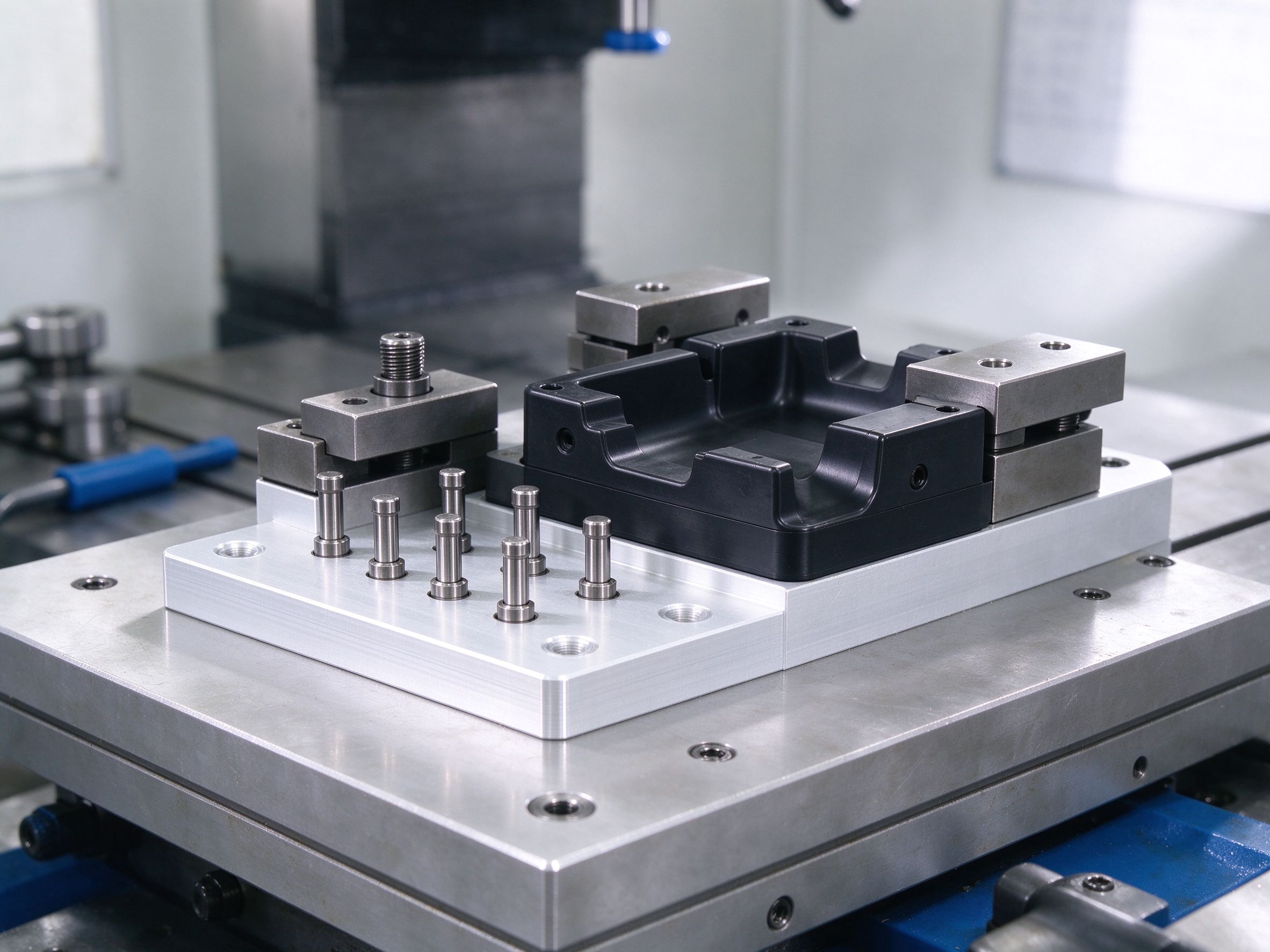
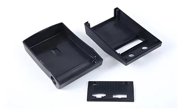
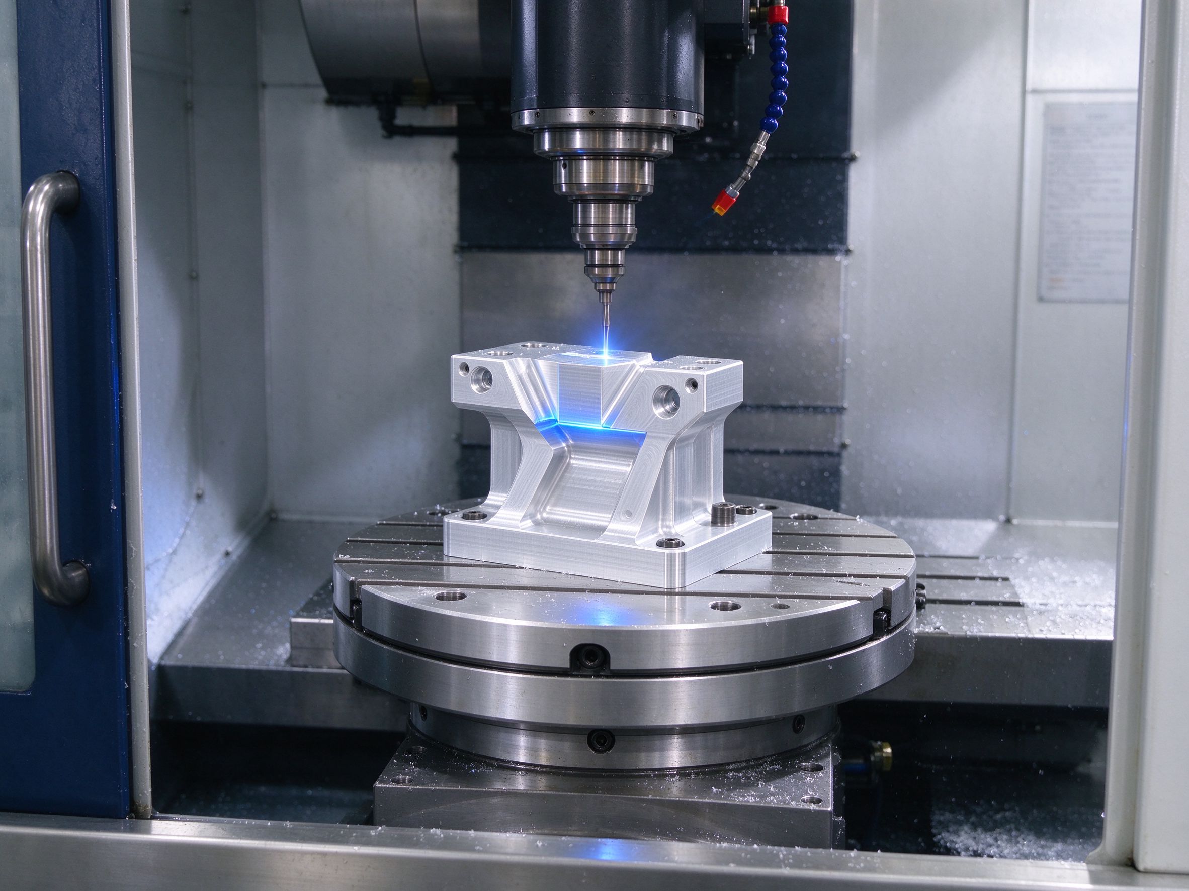
A representative workholding assembly: datum plate, locating pins, clamp blocks and a contoured nest, machined to the buyer's fixture drawing.
At a Glance
Goldcattle machines custom jigs and fixtures from your drawings: plates, locators, drill jigs, nests, soft jaws and inspection fixtures in aluminum, steel and engineering plastics, with CMM inspection of critical datum and position features. We review datums, clamp points, tool access, material and tolerance before cutting, and separate component dimensional accuracy from in-use locating repeatability. Complete fixture design, hydraulic or pneumatic control systems and line integration are scoped per project after engineering review rather than offered as a standard turnkey package.
What Are Jigs and Fixtures
Both hold the workpiece in a defined position. The dividing line is whether the tool is guided. This distinction matters in the drawing: a bushing bore or guide sleeve belongs to a jig, while a clamp and support arrangement belongs to a fixture.
| Comparison | Jig | Fixture |
|---|---|---|
| Core role | Locates and clamps the part, and guides the cutting tool | Locates, supports and clamps the workpiece; does not guide the tool |
| Typical parts | Drill jig, reaming jig with guide bushings | Milling fixture, assembly fixture, inspection fixture, nest |
| Common features | Guide bushing, locator pins, base plate, clamp details | Datum faces, support blocks, clamps, locating base |
| Buyer focus | Tool guidance and repeated hole position | Locating repeatability, clamp rigidity and stability |
Types of Jigs and Fixtures We Manufacture
The six groups below map to common workholding operations. Each card lists the structural features machined and the production step it serves; a multi-part fixture may combine several groups in one assembly.
Machining fixtures
Dowel holes, clamp holes, datum faces and locator positions that hold the part steady during milling or other machining.
Drill and reaming jigs
Guide bushing bores, pin holes and a locating body that repeat the same hole position across parts.
Assembly fixtures and nests
Locators, support blocks and clamp interfaces that keep components aligned during assembly, press-fit or bonding.
Inspection fixtures
Datum faces, locating holes and holding points that repeat the part position for gauge checks or CMM holding.
Soft jaws and nests
Contoured grip faces matched to the workpiece outline to hold irregular parts without marking or deflecting them.
Fixture plates and bases
Hole arrays, threaded holes, dowel interfaces and machine-table mounting points for modular or multi-station setup.
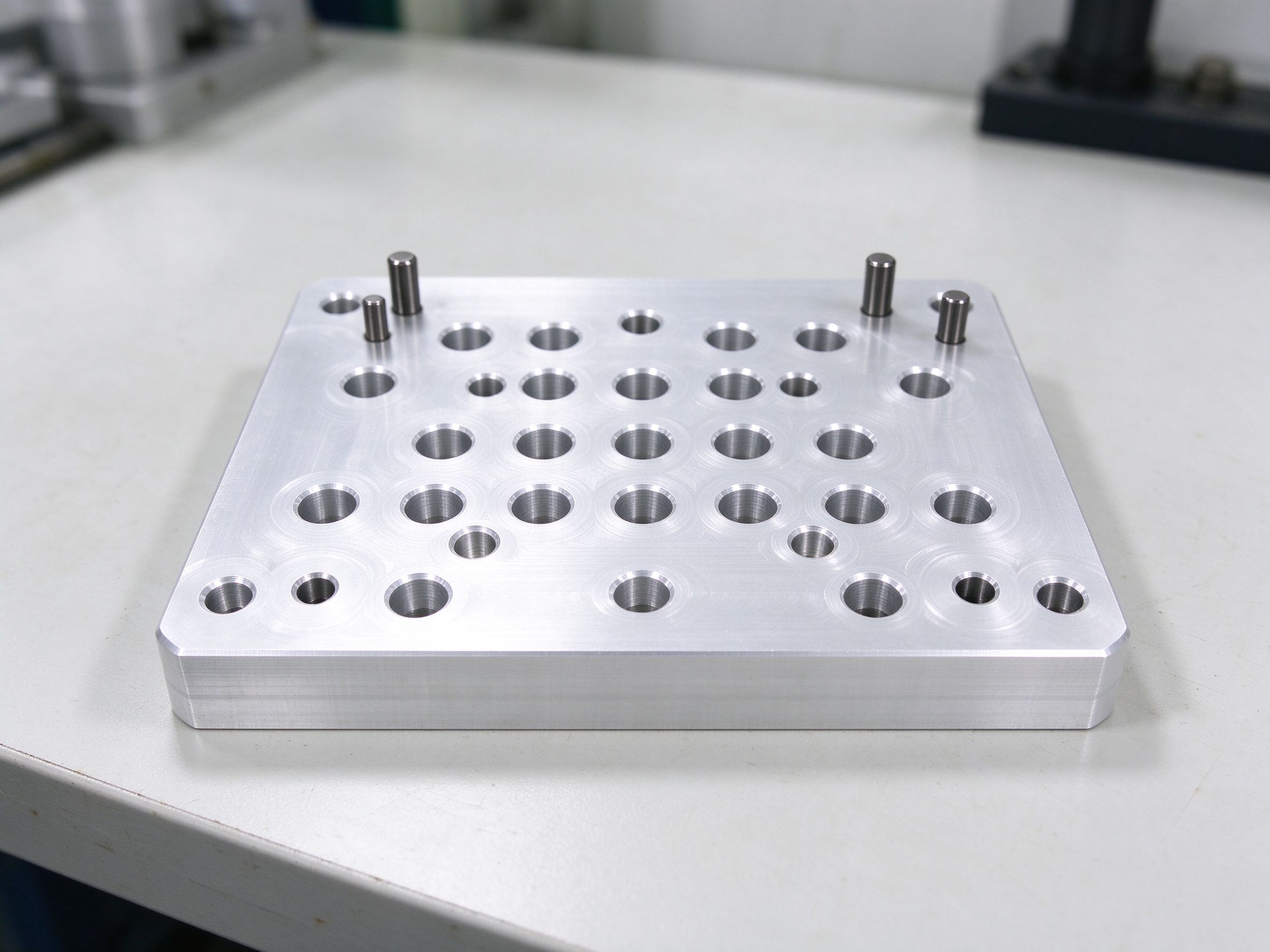
Locating and Clamping Principles
A fixture holds the part against a chosen datum scheme, and the clamp must keep it seated rather than lift it off the locators. The principles below explain what the drawing and DFM review check.
3-2-1 locating as a common case
A typical prismatic part is located by three primary datum points on a main face, two on a second direction and one on the third, covering six degrees of freedom in translation and rotation. This is one locating method, not the fixed rule for every part.
Other locators by shape
Cylindrical parts use V-blocks or ring seats, thin walls use soft jaws and auxiliary supports, irregular castings use a contoured nest, and multi-side parts use a locating plate or adapter base. Over-locating and clamp deflection are checked against the workpiece.
Clamp toward the datum
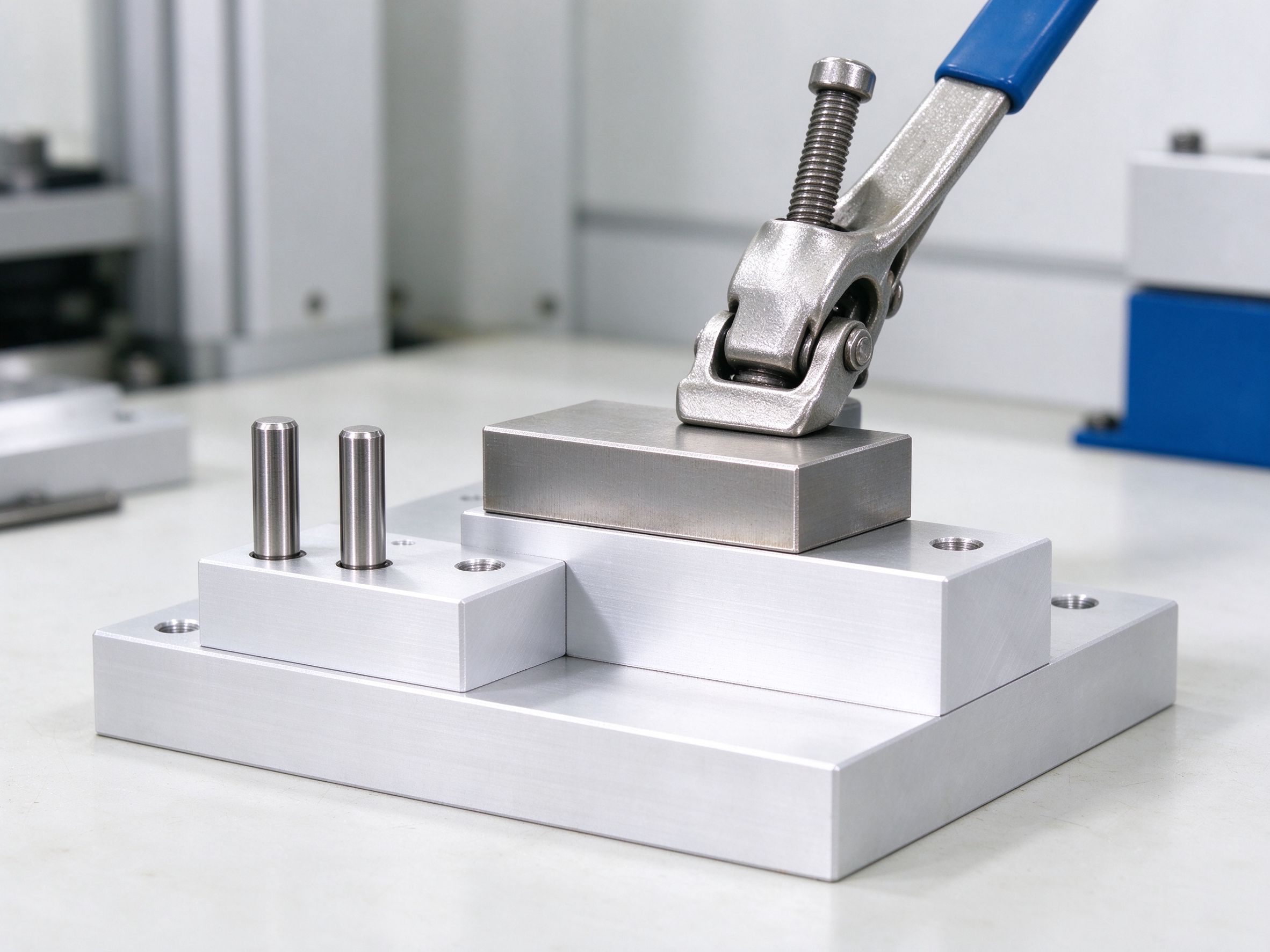
Clamp force should press the part onto its supports and locators. A direction that pulls the part off a locator, or force concentrated on a thin section, can seat it wrongly or deflect it before cutting.
Manual, toggle, pneumatic, hydraulic
Manual suits small lots and simple bodies, toggle suits repeated setup and assembly stations, pneumatic suits automated or high-cycle stations, and hydraulic suits high-load fixtures. Pneumatic or hydraulic cylinders and control circuits are sourced to buyer specification; we do not claim an in-house system design as standard.
Material Selection for Fixture Components
Fixture material follows the component role: rigidity, wear, contact behavior and working environment. Grade and hardness state are reviewed against the drawing; secondary heat treatment or surface treatment is stated with its measurement condition.
| Material | Typical fixture role | Selection notes |
|---|---|---|
| Aluminum 6061-T6 / T651 | Plates, fixture bodies, support blocks | Lightweight, easy to machine hole arrays and pockets; contact wear depends on use. |
| Aluminum 7075-T6 | Higher-strength light parts | Higher strength where a lighter, stiffer component is required; condition confirmed per lot. |
| Carbon / alloy steel 1045 and related grades | Load-bearing bases, clamp components | Strength and load capacity; hardness and heat-treat state are confirmed after review. |
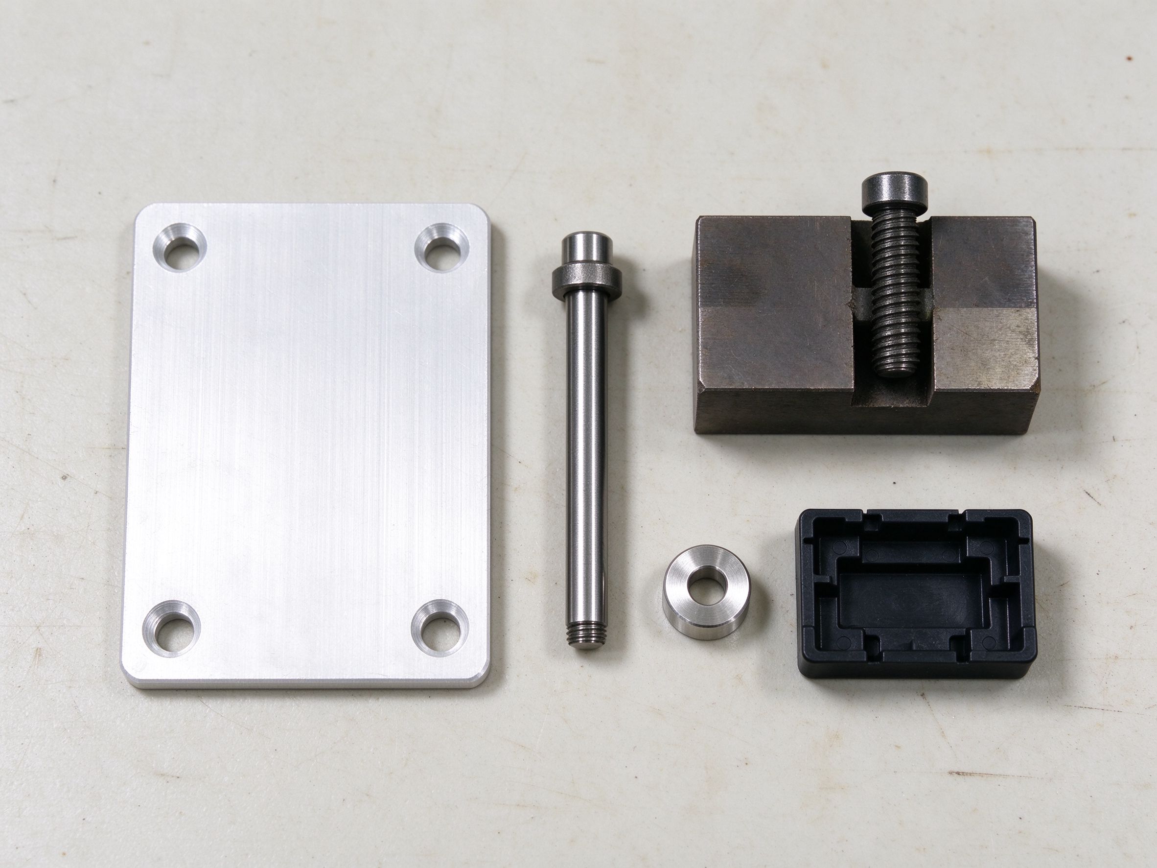
| Tool / wear steel for locators and bushings | Locator pins, guide bushings, wear contacts | Grade, hardness and dimensional stability selected for wear; grinding or EDM route agreed before cutting. |
| Stainless 304 / 316L | Corrosion or wash-down environment parts | Resistance to cleaning fluids and moisture; machined to the stated condition. |
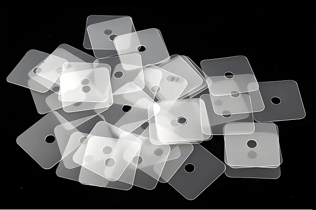
| POM / Delrin, PEEK | Non-mar nests, jaw inserts, insulating supports | Protect finished surfaces and lower metal contact; PEEK applies to special temperature, chemical or insulating needs, with cost and clamp creep considered. |
Machining Processes for Fixture Parts
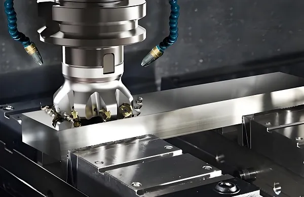
The existing CNC routes produce the features a fixture needs: datum faces, hole patterns, pin bores, threads, contoured nests and wear parts. Multi-face features are handled on 3-, 4- and 5-axis equipment; the chosen route depends on the design and cost, not on the machine alone.
| Process | Fixture features | Route note |
|---|---|---|
| 3 / 4 / 5-axis milling | Plates, bodies, pockets, locator blocks, contours | Five-axis simultaneous on the DMG MORI DMU 50 handles multi-face and compound-angle features in fewer setups where the design calls for it. |
| Drilling, tapping, reaming | Dowel holes, threaded holes, guide bores, pin holes | Hole position, thread class and bore fit are set on the drawing and checked against the inspection plan. |
| CNC turning | Shaft-style locators, pins, bushings, cylindrical seats | Reference turning range Ø2 to 320 mm; Swiss-type for small pins Ø0.5 to 20 mm where applicable. |
| Wire / sinker EDM | Hardened wear parts, internal contours, hard-metal details | Wire kerf 0.15 mm; hardened steel to 65 HRC per the disclosed process range. |
| Grinding / honing | Datums, contact faces, precision bores on selected features | Flatness, parallelism and finish on reviewed surfaces; the surface condition is stated on the report. |
Process and material range for general parts sits on CNC machining services; tight tolerance and finish detail is on tight tolerance CNC machining.
DFM and Engineering Considerations
Before cutting, the review checks that the locators, clamps and tool path can coexist on the same body. These six points are the standard review set for a custom fixture.
Datum reference planning
Match fixture datums to the workpiece functional datums so the part seats on faces that matter to the next operation.
Clamp force and deformation
Check thin walls, soft sections and contact points for deflection; add supports or spread the contact area where needed.
Tool clearance
Verify cutter reach, bolt clearance, deep-hole access and tool-change travel so clamps and locators do not block the cut.
Chip and coolant flow
Leave passages for chips and coolant to leave the work zone, especially in pockets and around nested parts.
Wear and replaceable parts
Design hardened pins, bushings, wear pads or nest inserts as replaceable contacts so the main body survives long runs.
Loading and unloading
Check part entry and exit, locating lead-in, operator access and any poka-yoke feature that prevents wrong placement.
Tolerance, Fit and Repeatability
Fixture accuracy is split into three separate ideas: the CMM's measurement capability, the tolerance the component itself must hold, and how repeatedly the workpiece locates in use. They are not one single number.
| Feature class | Standard reference | Enhanced / reviewed |
|---|---|---|
| Machined linear dimensions | ±0.02 mm | ±0.01 mm; ±0.005 mm on selected qualified critical features after review |
| Hole position | ±0.05 mm | ±0.02 mm; ±0.01 mm on reviewed multi-datum or long patterns |
| Precision bores | H9 | H7; tighter H6 or reamed fit assessed per project |
| Base flatness, large planes | 0.05 mm per 100 mm | 0.02 mm per 100 mm on reviewed large planes |
| Contact-face finish | Ra 1.6 µm | Ra 0.8 to 0.4 µm on reviewed faces; below that needs grinding, honing, lapping or a post-process |
Standards on the drawing are followed as written: ASME Y14.5 GD&T language for US buyers, ISO GPS and ISO 1101-style geometric controls where the drawing specifies them. Working to a buyer's drawing standard is not a product certification to that standard.
Inspection and Documentation
Quality covers two layers: the fixture's own dimensions, and whether it locates the workpiece correctly under the intended condition. The inspection plan states the method, datum and clamping state for each checked feature.
What the CMM and gauges verify
- Base flatness and datum faces
- Locator hole position and pin-to-pin distance
- Parallelism and perpendicularity of locating faces
- Guide bushing fit and bore condition
- Thread quality with gauge check
- Contact-face finish with profilometer
Checks against a master part
- Master part fit and seating check
- Repeated loading and locating check
- Clamp deformation check on thin or soft sections
- Tool-access and reach check against the operation
- Locator, bushing and clamp assembly check
| Deliverable document | Purpose |
|---|---|
| Dimensional inspection report | Machined sizes and geometry checked against the drawing. |
| CMM inspection report | Critical position, flatness, parallelism, perpendicularity and GD&T. |
| Material certificate, EN 10204 3.1 | Grade and lot traceability with qualified lots, where requested. |
| Hardness report | Heat-treated or wear-part hardness, where the project applies it. |
| First article inspection | FAI prepared per AS9102 on request; not a certified scope statement here. |
| Component list and revision record | Assembled parts list and drawing or model revision for repeat orders. |
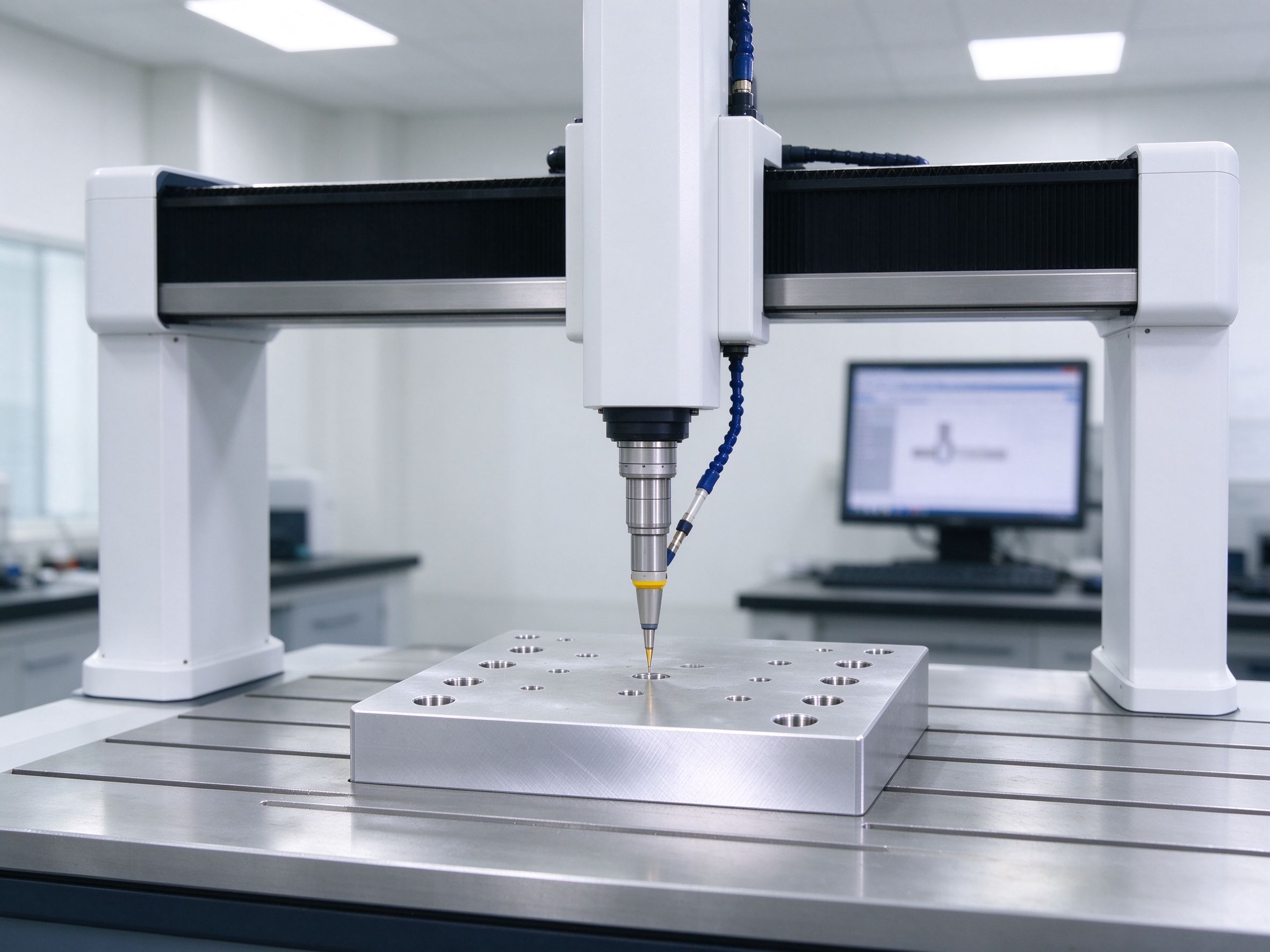
Inspection equipment and certification scope are listed on the quality certifications page.
Applications We Map to Operations
Applications are described by workpiece and operation rather than by claimed sector certification. The same locating logic serves CNC shops, equipment builders and assembly or inspection lines; sector records follow the buyer's part and documentation requirements.
CNC machine shops
Soft jaws, locating fixtures and base plates that reduce repeated setup and keep the part seated across a batch.
OEM machinery builders
Assembly locators, support nests and drill jigs that align components during build and repeated hole work.
Automation integrators
Locator plates, nest bodies and support brackets matched to the machine or gripper interface specified on the model.
Assembly stations
Clamp-and-locate bodies that hold parts for press-fit, bonding, fastening or repeat assembly alignment.
Inspection and metrology
Nests and holding fixtures that repeat the part position for gauges, probes and dimensional checks.
Precision industrial products
Non-mar nests and contoured soft jaws for finished surfaces and thin or irregular parts.
From Drawing to Delivered Fixture
One project contact follows the fixture through review, machining and inspection. Component finishing and assembly follow the agreed scope; a full assembled-and-tested workholding package is confirmed after engineering review.
Drawing review and DFM
Check datums, locators, clamp points, material, tolerance and tool access against the model and workpiece drawing.
Process and material plan
Select material grade, machining route, wear parts and secondary treatment; set inspection points.
CNC machining
Machine the plate body, locators, pin bores, clamp features and nest profile on the planned route.
Finishing and component prep
Deburr, coordinate any heat treatment or surface finish, and prepare components per the agreed assembly scope.
Dimensional inspection
CMM and gauge checks on datums, position, fit and finish; record condition and method on the report.
Functional check and delivery
Master-part fit or repeated-loading check where agreed; assemble the document pack and protect the parts for dispatch.
What to Send With Your RFQ
These inputs let the review confirm feasibility, route and inspection plan, and return an honest price and lead time rather than a generic estimate.
| RFQ input | Why it matters |
|---|---|
| 3D model | STEP, IGES, Parasolid or SLDPRT for geometry, holes and clamp features. |
| 2D engineering drawing | Datums, GD&T, tolerance, threads and finish that define acceptance. |
| Workpiece drawing | Matches locating faces, pin positions and nest profile to the part held. |
| Operation and machine | Milling, drilling, assembly or inspection; machine model, table or fixture interface. |
| Fixture material and clamp type | Sets rigidity, wear, environment and whether manual, toggle, pneumatic or hydraulic is requested. |
| Repeatability requirement | Allowed position variation and the method used to check it, plus master-part plan. |
| Quantity and batch plan | Single piece, prototype, low volume or repeat order; wear-parts strategy follows volume. |
| Inspection documents | CMM report, dimensional report, material certificate, hardness or FAI as required. |
Frequently Asked Questions
What is the difference between a jig and a fixture?
Can you manufacture custom jigs and fixtures from our drawings?
What types of machining fixtures do you make?
Can you machine fixture plates, locators and soft jaws?
Which materials are used for fixture components?
How do you protect locating repeatability in a fixture?
What tolerances can you hold on fixture parts?
Can you machine hardened steel locators and guide bushings?
Do you inspect fixtures on the CMM and supply reports?
What files are required to quote a custom fixture?
Send your fixture drawing for a manufacturing review
Share the 3D model, 2D drawing, workpiece outline, operation, machine interface and quantity. The review checks datum and locator feasibility, material and wear parts, tool access and the inspection plan, then returns a route, DFM notes and an estimate.
One inquiry per project; NDA available before file exchange. Full design-and-build scope is confirmed after engineering review.
See quality certifications and inspection scope →