Custom CNC Machined Parts for Robotic End Effectors (EOAT)
A robot cell rarely fails because a jaw was a tenth of a millimeter off. It fails at the interface. An adapter plate whose pilot boss and dowel pattern do not agree with the wrist flange does not produce one bad part — it rotates and offsets every tool built on that plate, on every cycle, for the life of the cell. This page is about machining those parts: what they have to do, how the interfaces are held, and where the real risks sit.
At a Glance
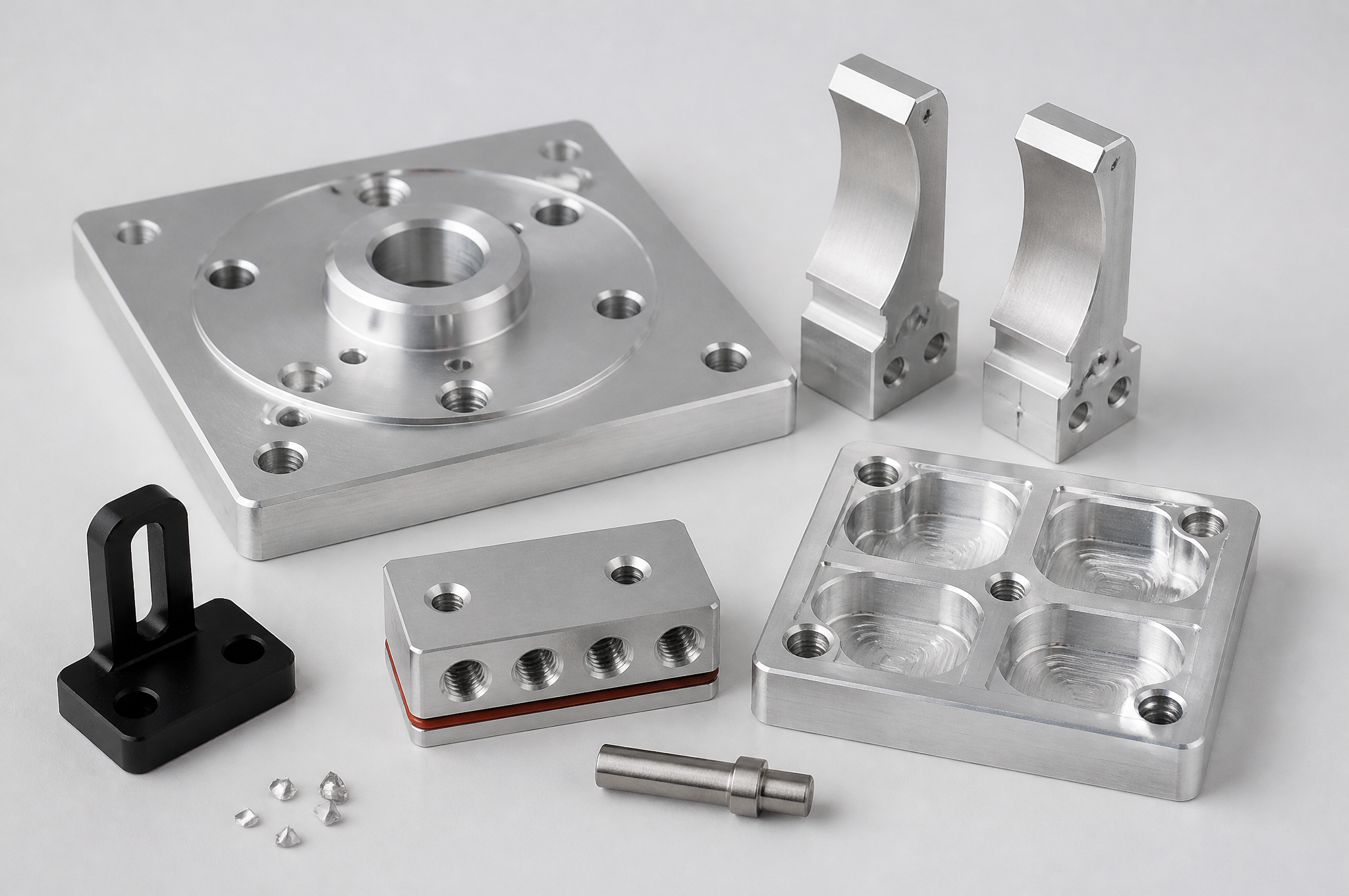
A robotic end effector is bought as a set of interfaces, not a set of parts. The wrist flange, the adapter plate, the tool changer, the mounting plate and the gripper all stack in one line, and each joint in that stack has a position and an orientation. A part that is in tolerance on its own can still make the stack wrong, because what matters is where one side of the plate sits relative to the other. This is why interface error is the expensive kind: it is repeatable. Every part the cell makes inherits the same offset, and every tool built on the same plate inherits it too. Machining these components is mostly the discipline of holding one datum across two faces and proving it with a measurement, not the pursuit of a small number on a single feature.
Where This Page Fits
The site has a general CNC machining service and several capability pages. None of them address what is different about robot tooling, so this page does that and hands everything else back.
| Page | What it answers | What this page does about it |
|---|---|---|
| This page | How EOAT components are designed, machined, finished and inspected, and what the buyer has to define | — |
| CNC machining services | Machines, envelopes, general materials and lead times | No machine list here |
| 5-axis machining | Simultaneous and 3+2 work, CAM simulation, datum and fixture planning | One section here, on when 5 axes is unnecessary |
| Multi-sided 5-axis brackets | General multi-face bracket work | EOAT-specific brackets only |
| Tight-tolerance machining | Achievable values by feature and material, and metrology in depth | Which features matter, not what the limits are |
| Engineering plastics | POM, PEEK, PTFE and nylon behavior in general | Plastic contact parts in robot grippers |
| Stainless machining | Grades, corrosion behavior, cutting practice | Where stainless makes sense in a tool |
The Parts: Twelve Components, Three Jobs
Everything bolted to a robot wrist does one of three jobs: it connects, it grips, or it positions something small and exact. Knowing which job a part does tells you which features will be inspected and which ones will be ignored.
| Component | Job | What decides whether it works | Usual material |
|---|---|---|---|
| Robot flange adapter plate | Connects | Pilot boss diameter, bolt circle, dowel positions, face flatness, stack height | 6061-T6, 7075-T6 |
| Tool changer adapter plate | Connects | Robot-side pattern and tool-side pattern held to one datum; centring features; flatness of both faces | 6061-T6, 7075-T6, steel where the changer requires it |
| EOAT mounting plate | Connects | Hole pattern, boss height, rigidity under acceleration, weight | 6061-T6, 7075-T6 |
| Intermediate spacer or riser | Connects | Parallelism of the two faces; hole pattern transfer; added height and mass | 6061-T6, POM for isolation |
| Gripper fingers | Grips | Contact profile, matched pair dimensions, mounting hole position, tip stiffness | 6061-T6, 7075-T6, POM, nylon, PEEK |
| Gripper jaws | Grips | Jaw opening relative to stroke, contact faces, wear surfaces | Steel, 7075-T6, hardened inserts |
| Replaceable contact pads | Grips | Non-marring surface, screw counterbores below the contact face, flatness of the pad | POM, PEEK, PTFE, urethane |
| Vacuum cup mounts | Connects | Cup position and height, port alignment, seal face flatness | 6061-T6, POM |
| Vacuum manifold blocks | Connects | Port threads, internal passages, O-ring grooves, seal face finish, burr-free interiors | 6061-T6 |
| Sensor and camera brackets | Positions | Mounting hole pattern, angle, datum reference, adjustment slot, cable clearance | 6061-T6, black anodized, steel |
| Locating nests and fixtures | Positions | Nest geometry against the part, datum faces, repeatability of location | POM, PEEK, aluminum, steel |
| Guide and wear parts | Positions | Sliding clearance, wear surface, replaceability | Hardened steel, bronze, PEEK |
The table also tells you where the money goes. Connection parts are inspected on hole position and face flatness. Gripping parts are inspected as a pair and on the contact profile. Positioning parts are inspected on where the feature ends up relative to the bracket's own datum, because a camera bracket that is a degree out costs more in calibration time than in machining.
The Interface Fails First
Ask what breaks a robot cell and most people point at the gripper. In practice the gripper usually works; the plate behind it is what was wrong. An interface error has four unwelcome properties: it is small enough to pass a visual check, it repeats on every cycle, it transfers to every tool built on the same plate, and it cannot be adjusted out without re-machining or shimming.
Shaded boxes are the parts on this page. Every arrow is a fit that has to hold position and orientation, and every one of them is a place where a small error becomes permanent.
The features that carry that responsibility have names worth knowing, because they are the features a drawing has to define and a report has to prove:
| Feature | What it does | What goes wrong when it is loose |
|---|---|---|
| Bolt circle (PCD) | Sets where the screws sit around the flange center | Holes do not line up; the plate is forced on and sits stressed |
| Centring boss or register | Puts the plate on the robot axis without relying on the screws | The tool runs eccentric; every offset repeats on every part |
| Dowel positions | Fix rotation, and take load off the screws in shear | Clocking drifts; the tool is rotated by a fraction of a degree every time it is refitted |
| Clocking or key feature | Defines the one intended orientation | The tool can be fitted in more than one position, and eventually is |
| Mounting face flatness | Keeps the stack from rocking when screws are tightened | The plate pulls flat under torque and the far side lifts; the stack is preloaded and the tool tilts |
| Stack height | Sets how far the tool center sits from the wrist | Different tools sit at different distances, and every one needs its own TCP |
| Thread depth and grade | Defines how much engagement the screws get | Blind holes too shallow hold nothing; too deep foul the robot face |
On ISO 9409-1. The circular flange interface on industrial robots is standardized in ISO 9409-1, which gives the plate dimensions, the bolt pattern and the designations that go with them. It is a good reference and a useful shorthand on a drawing. It is not a substitute for your robot's own documentation: the standard does not set payload, and two robots that both quote a nominal flange size can still differ in pin arrangement and screw requirements. So the rule here is simple — we machine the interface your drawing and your robot manual define, and we do not assume a pattern because the flange is nominally the same size.
Two Sides, One Datum
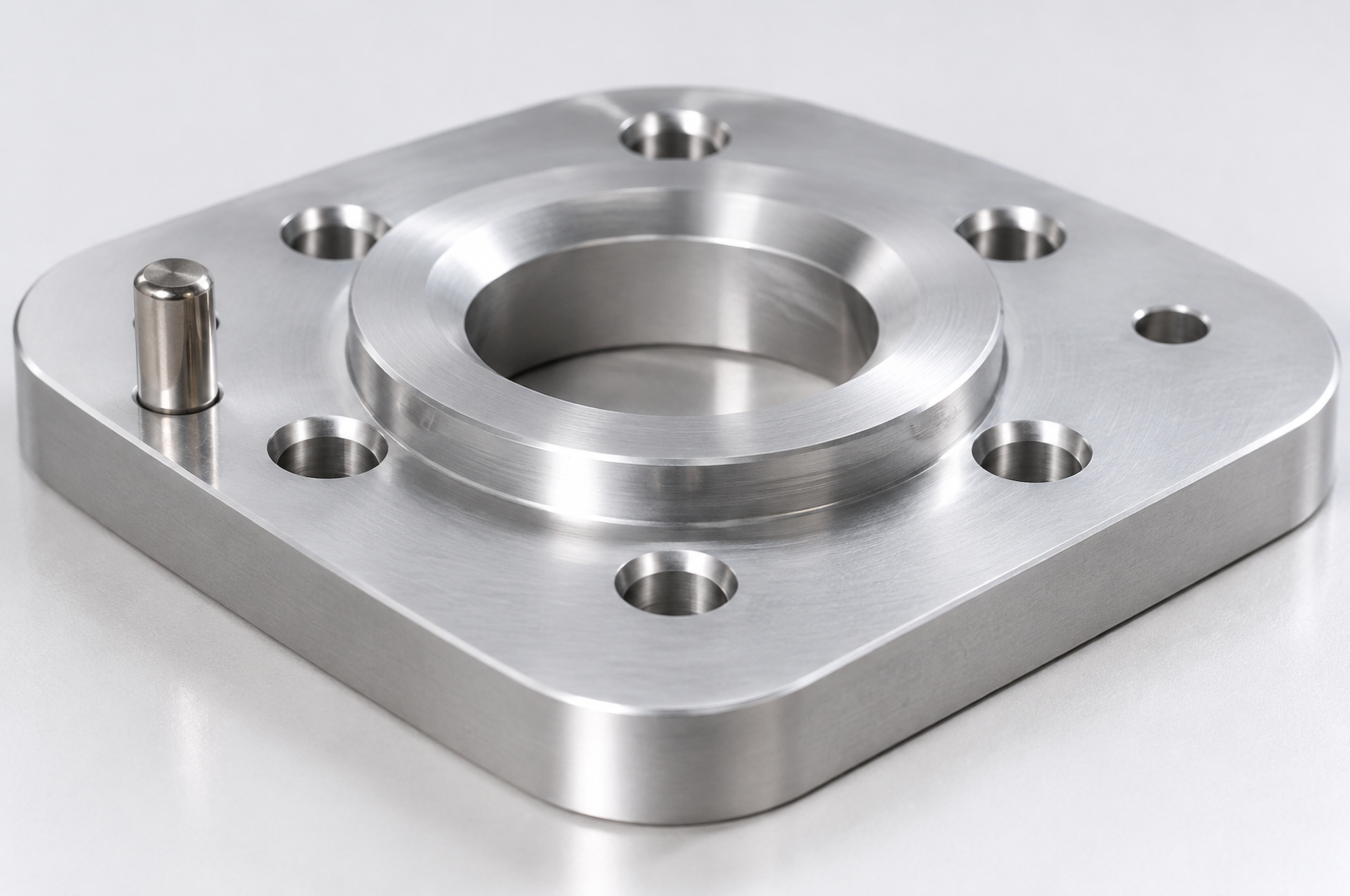
An adapter plate is a small part with two different drawings on it. One side has to fit the robot; the other has to fit the tool. If each side is machined from its own convenient reference, the two patterns drift independently and the plate becomes a small, expensive angle bracket.
| Decision | The usual mistake | The practice that avoids it |
|---|---|---|
| Which face is the datum | Each side is set up from its own face because it is easier to clamp | One face is nominated as the datum, machined first, and every later feature on both sides is referenced to it |
| How the second face is reached | The part is flipped and picked up from an edge or a vice jaw | The flip is made against a machined feature, or the second side is cut without a flip on a 4-axis or 5-axis setup |
| Boss and bolt circle | Bored in a separate operation, so the boss is eccentric to the pattern | Boss, bolt circle and dowels are cut in the same setup; eccentricity is then a single measurable value instead of an unknown |
| Flatness after clamping | Measured on the machine while held in the vice | Measured free, because a plate pulled flat by clamping springs back when released |
| Two-face pattern relationship | Only each face is inspected | The angular relationship between the two patterns is measured and reported, since that is what the tool actually inherits |
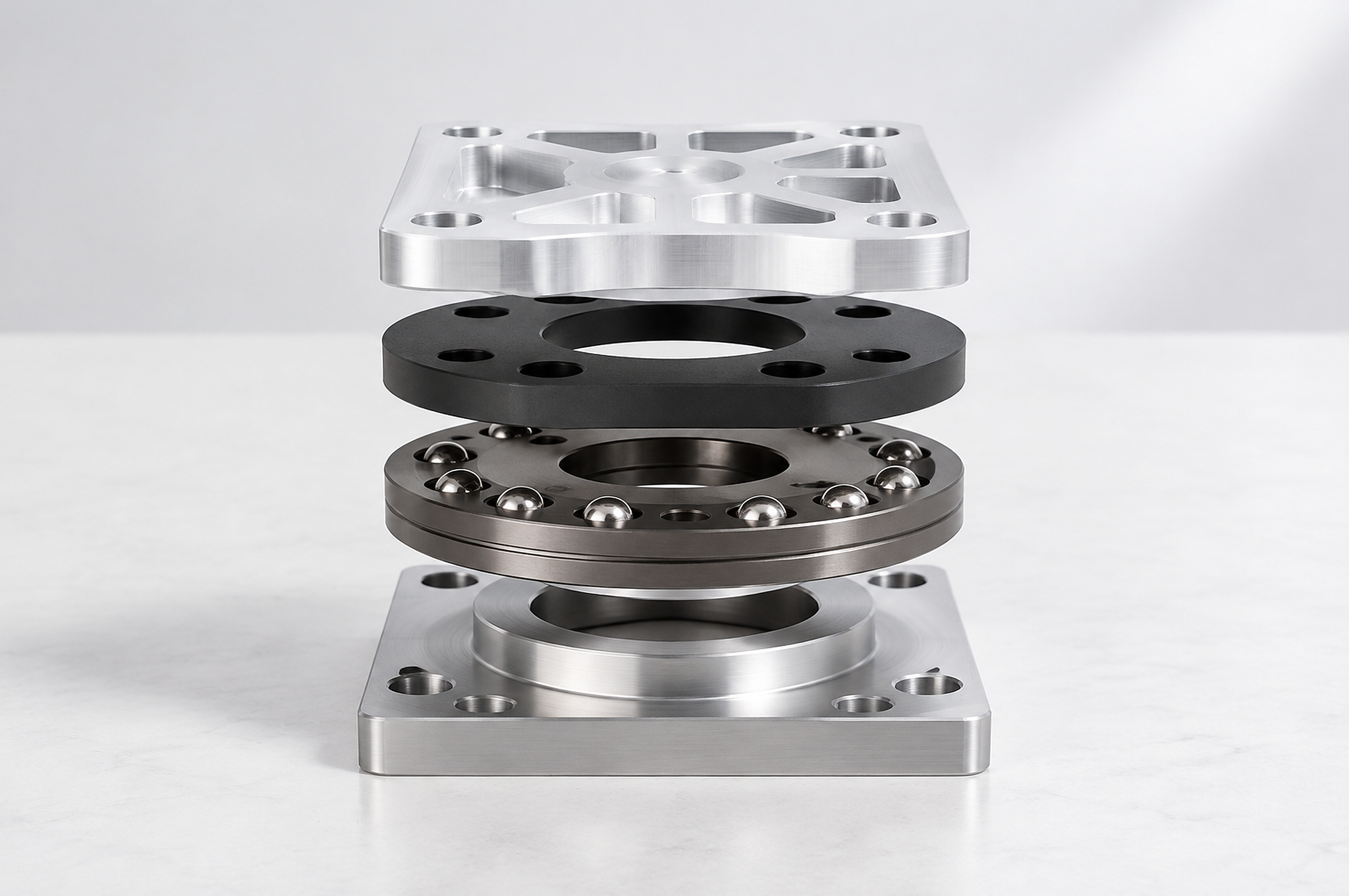
Light but Stiff, Not Thin
Every gram on the end effector is a gram the robot cannot use for the workpiece, and it counts twice, because the mass also sits at a distance from the wrist. Inertia grows with mass times the square of that distance, so a plate that is 20 mm further out is worse than a plate that is 20 g heavier in the same place. That is why the first instinct — make the plate thinner — is usually the wrong one.
A thin plate has two problems. It deflects under the acceleration of the move, which shows up as the tool lagging behind the commanded path and as the gripper closing on a position it never quite reaches. And it rings after the move stops, which matters for anything that has to settle before it grips. The trade is not weight against strength; it is weight against stiffness, per unit of distance from the wrist.
| Lightening move | When it helps | When it hurts |
|---|---|---|
| Pockets in low-stress areas | The material removed is far from the load path between the wrist and the tool | The pocket crosses the span between a dowel and a bolt, which is exactly where shear runs |
| Ribs left between pockets | They keep bending stiffness where the plate spans open space | They are thin, sharp and unsupported, so they chatter during machining and ring in service |
| Reduced wall thickness overall | Rarely — only where a drawing and a load case support it | Almost always, if it is done to save weight rather than to solve a stiffness problem |
| Tapered or stepped thickness | The bending moment falls away from the mounting face | It creates internal corners that need a radius, and it is harder to hold flat |
| Material change, same geometry | 7075-T6 replaces 6061-T6 where strength per gram matters | The part needs corrosion resistance or weldability, where 6061 is the better base |
| POM or PEEK for contact parts | A steel or aluminum contact face is marking the product | The pad is also a structural member carrying the gripping load |
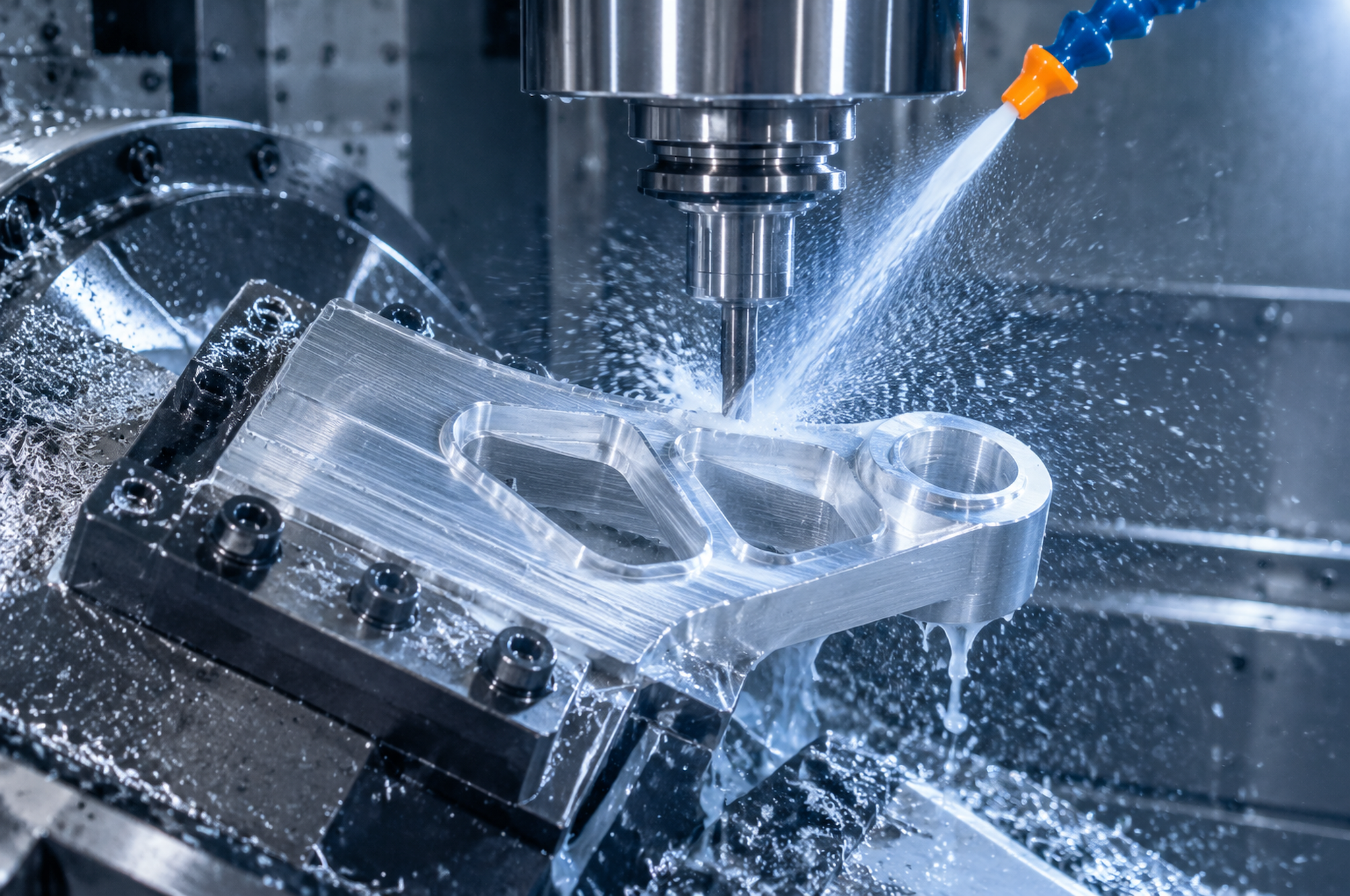
Gripper Fingers and Jaws
Fingers are the parts buyers ask about most and specify least. A drawing usually gives length, width, thickness and a hole pattern, and leaves out the two things that decide whether the gripper works: the contact profile against the actual workpiece, and the relationship between the two fingers of the pair.
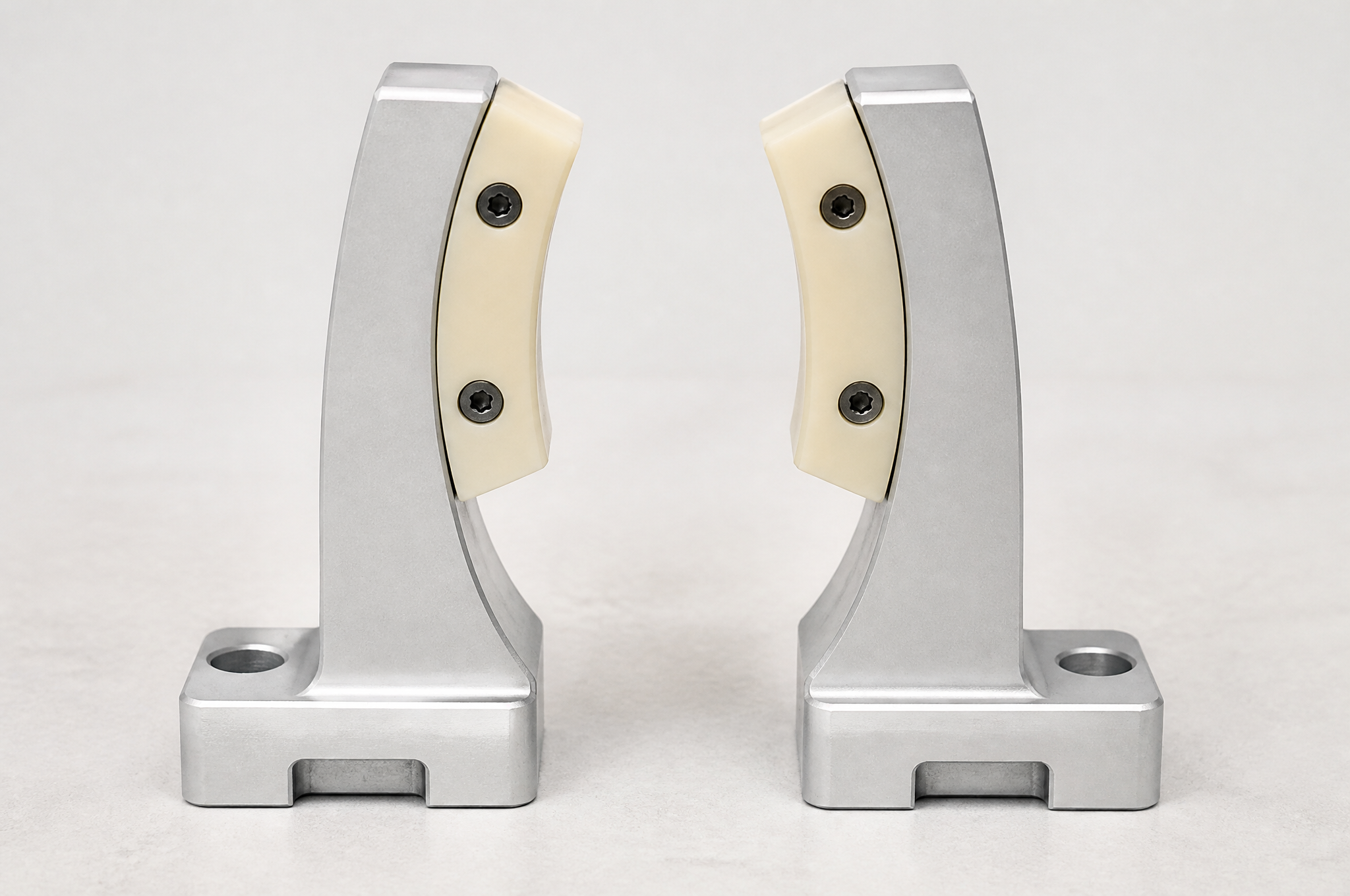
| Feature | Why it matters | How it should be defined |
|---|---|---|
| Contact profile | Decides whether the workpiece is gripped on two lines, two points or a face | Give the workpiece model or a section through the grip, not just a radius |
| Pair relationship | An offset between the two fingers grips off-center and lifts the part at an angle | Dimension the pair: gap, symmetry, and matched mounting height |
| Mounting features | Must agree with the gripper body's slot, pin or jaw interface | Reference the gripper interface drawing, not a measured sample |
| Tip thickness and reach | Long thin tips bend; a bent tip grips the part at a different height each cycle | State the reach and the load, and let the section follow from it |
| Contact material | Aluminum marks some products; POM and PEEK do not, but carry less load | Say what the part touches, and whether marking is a defect |
| Replaceable pads | Wear part that should be swapped, not the whole finger | Define the seat, the screw type and the counterbore depth below the contact face |
Matched pairs are a separate order line. Two fingers machined independently to the same drawing can each be inside tolerance and still not form a good pair, because tolerance on a hole and tolerance on a profile can push in the same direction. When a project needs a pair, we machine them as a pair, hold them together through finishing, and report the pair dimensions as a pair. This is a process decision made at quoting time, not a note added at inspection.
Vacuum and Air Blocks
A manifold block looks like a machined brick and behaves like a pressure vessel with a gasket. What fails is not the outer shape but the joints: the thread that has to seal, the groove that has to hold an O-ring at the right squeeze, and the passage that has to be clear of burrs.
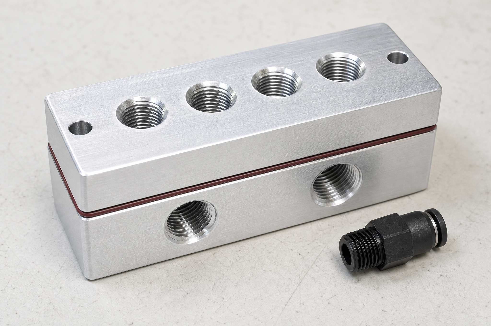
| Feature | Manufacturing consequence | What the drawing must say |
|---|---|---|
| Port threads | Thread depth and class set how far a fitting seals; blind holes leave chips if not cleaned | Thread standard, depth, and whether a sealing washer or taper is used |
| Internal passages | Cross-drilled holes meet inside; the intersection leaves a burr nobody can see | Passage diameter, drill depth, and whether the ends are plugged |
| O-ring groove | Width, depth and side-wall finish control squeeze; a polished groove can leak as easily as a rough one | Groove dimensions with the O-ring section, and the surface finish inside the groove |
| Seal face | Flatness and finish decide whether the joint seals at low pressure | Flatness and Ra on the sealing land, separately from the rest of the face |
| Internal deburring | Hand deburring reaches the ends of passages, not the intersection inside | Whether deburring is required, and what method is permitted |
| Cup mounting holes | Position and height set the suction pattern and the clearance to the product | Cup pattern relative to a datum, and the height of each face |
Sensor and Camera Brackets
These are the smallest and cheapest parts on the tool, and the ones that cost the most in commissioning time. A camera bracket that sits a degree out does not stop the cell; it turns a calibration that should take ten minutes into an afternoon, and then leaves a fixed offset nobody can explain a month later.
- Position and angle are the product. The bracket exists to put a sensor at a defined point looking in a defined direction, so both the position of the mounting holes and the angle of the sensor face have to be defined relative to a datum on the bracket — not left to be set on the robot.
- Adjustment slots are a design decision. A slot gives you range to set in the field, and gives away repeatability. If a slot is needed, its direction, travel and the clamping face should be explicit, so that the adjustment moves the sensor the way you expect and not in two directions at once.
- Cable and connector clearance is part of the drawing. Brackets that fit the sensor and not the cable are common; the connector body and the bend radius need space behind the mounting face.
- Stiffness beats elegance. A thin cantilever holding a camera will vibrate for as long as the robot is moving, which is exactly when the image is taken.
Materials: What Each One Does to the Part
Grade selection on a tool is rarely about strength alone. It is about what the part touches, how much it weighs, whether it will be cleaned, and whether it will be taken off and put back on a thousand times. The table below is written as consequences rather than properties.
| Material | Where it earns its place | Where it bites |
|---|---|---|
| 6061-T6 aluminum | Adapter plates, mounting plates, brackets, vacuum blocks: cuts fast, stays flat, anodizes evenly, widely available | Lower strength than 7075, so a thin load-bearing section needs more depth rather than a different grade |
| 7075-T6 aluminum | High-load adapter plates and fingers where mass matters; good strength per gram | Less corrosion resistant than 6061, so it wants anodizing; harder to form and less forgiving of sharp internal corners |
| 304 stainless | Jaws, wear parts, brackets in washdown or food-adjacent cells | Galls and work hardens; threads and sliding fits need care, and machining time is far longer than aluminum |
| 316L stainless | Parts exposed to cleaning chemicals or chloride, where 304 is not enough | Cost and machinability; it is not automatically the right answer to every corrosion question |
| POM (acetal) | Contact pads, non-marring fingers, nests, wear strips: low friction, stable, machines cleanly | Creeps under sustained load, and a thin POM finger deflects more than the aluminum it replaced |
| Nylon (PA6 / PA66) | Tough contact parts and guards where some give is wanted | Absorbs moisture and changes size, so a nylon part made to a tight fit today may not fit next month |
| PEEK | High-temperature or chemically aggressive cells, and cleanroom-compatible contact parts | Cost, and it needs the right machining approach; it is wasted on a part that only needed POM |
| PTFE | Sliding contact and low-friction faces where nothing may stick | Cold flows under load: a press fit loosens and a thin section deforms, so it is a contact material rather than a structural one |
Two habits prevent most material problems on these parts. Say what the part touches — product surface, cleaning agent, temperature — rather than only naming a grade, because the same grade behaves differently in a washdown cell and a dry one. And match the material to the job in the stack: a stainless jaw bolted to an aluminum plate in a wet cell is a galvanic pair with a slow, predictable failure.
Which Process, and Why Not Always Five Axes
Not every EOAT component needs a five-axis machine, and quoting one that does not is an expensive way to look capable. The route follows the geometry, and the geometry of these parts is usually simpler than the reputation of the industry suggests.
| Process | Right for | Why not something else |
|---|---|---|
| 3-axis milling | Flat plates with pockets, hole patterns, bosses and profiles reached from one direction | The cheapest route by a wide margin; a second setup costs more than the extra axis would |
| 3-axis with a second setup | A plate with features on the back, or a bracket that needs two opposing faces | Still cheaper than 5-axis when the part has a clear datum to flip against |
| 4-axis indexing | Fingers and jaws with features around a length, or several identical parts on one fixture | Indexing repeats position without re-clamping, and one program runs the whole fixture |
| 3+2 (positional 5-axis) | Angled faces, cross holes, brackets with features pointing in several directions | Set once, machined from five directions, without the programming and verification load of continuous motion |
| Simultaneous 5-axis | Contoured contact profiles, swept surfaces, undercut geometry that has to be cut in one pass | The right tool when the surface must be cut continuously; overkill for a pocket with an angled wall |
| CNC turning | Dowel pins, spacers, bushings, cup holders, round stand-offs | Round parts belong on a lathe; milling them is slow and leaves a poorer surface |
| Wire EDM or grinding | Hardened inserts, thin slots, sharp internal corners, precise flat faces on a hardened part | Used where a cutter cannot reach or where hardness rules out milling |
The practical consequence for a buyer: the process should appear in the quotation, because it explains the price and predicts the risk. A plate quoted for 5-axis work that only needs 3-axis is a plate you are overpaying for. A bracket quoted for 3-axis work that needs four faces is a bracket that will be re-clamped three times, and the tolerance will show it.
Finish, and What It Does to the Fit
Surface treatment is the step most often left off the drawing and most often regretted, because a coating is a dimension. An anodized layer grows into the surface and out of it, so a bore gets smaller and a boss gets bigger. If the drawing does not say whether the tolerance applies before or after treatment, the part will be made to one interpretation and inspected against the other.
| Treatment | What it does for the part | What it does to the size | What to specify |
|---|---|---|---|
| Clear anodizing | Wear and corrosion protection with the machined look kept | Adds a thin film on all surfaces: holes tighten, bosses grow | Whether fits are masked, and whether inspection is before or after |
| Hard anodizing | Much higher surface wear resistance on aluminum jaws and wear faces | Adds more than clear anodizing, and reduces fatigue strength at sharp corners | Masked areas, edge radii, and the fit allowance for the thicker film |
| Bead blasting | Even matte appearance, hides tool marks, breaks edges slightly | Removes a trace of material and rounds edges; not a size-controlled process | Whether sharp edges must stay sharp, and the finish before blasting |
| Passivation | Removes free iron from stainless surfaces after machining | Effectively no dimensional change | That it is required at all, and after which operations |
| Electropolishing | Bright, clean stainless surface with burrs removed | Removes material, so bores grow and thin edges round | Which faces may be polished, and the allowance on fitted features |
On a robot tool there are three places where this matters more than elsewhere: the dowel holes, which are a location fit and cannot be allowed to tighten; the centring boss, which is a clearance fit that cannot be allowed to grow into an interference; and the seal grooves on a vacuum block, where a film changes the squeeze on an O-ring. All three are cheap to mask and expensive to rework.
Inspection: What Is Measured on Which Part
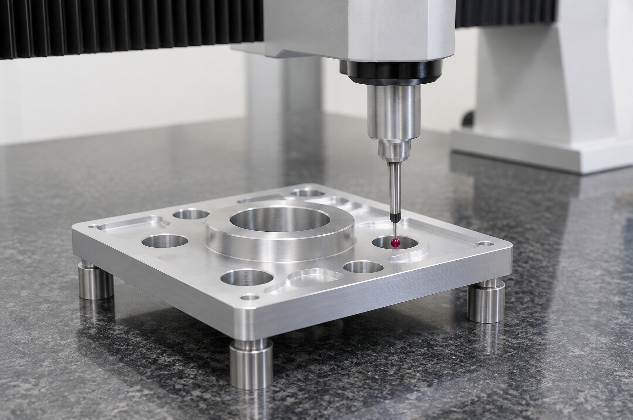
Inspection follows function. There is no single tolerance figure that covers a gripper finger, an adapter plate and a vacuum block, and a supplier who quotes one for all three has not thought about the parts.
| Part | Characteristics that matter | How they are checked |
|---|---|---|
| Robot flange adapter plate | Bolt circle, boss diameter and position, dowel positions, face flatness, thickness | CMM for position and form; bore and thread gauges for holes; free-state flatness |
| Tool changer adapter plate | Both hole patterns, their angular relationship, boss and recess depths, flatness of both faces | CMM from one datum, reporting both patterns in the same coordinate system |
| EOAT mounting plate | Hole pattern, boss heights, pocket depths, wall and rib thickness, flatness | CMM for position; thickness gauge or CMM scan for walls; flatness free |
| Gripper fingers | Mounting hole position, contact profile, pair dimensions, tip thickness | CMM or profile projector for the profile; pair dimension reported as a pair |
| Vacuum manifold block | Port threads, groove width and depth, passage positions, seal face flatness and finish | Thread gauges, CMM, roughness tester on the sealing land |
| Sensor and camera brackets | Hole position, sensor face angle, datum references, slot geometry | CMM for position and angle relative to the bracket datum |
What comes with an order depends on what is agreed, but these are the documents that carry weight:
- Dimensional inspection report — the characteristics listed above, with values, the instrument used and the datum they were measured from. A report that says "OK" is not a report.
- First article inspection — every characteristic on the drawing measured once, before the run continues, so that the acceptance basis for repeats is fixed early.
- Material certificate — the grade and the heat or lot, which is what makes a later repeat order comparable.
- Pair report for matched parts — the dimensions of the pair as an assembly, not two separate sheets.
From Prototype to Repeat Production
Robot tooling programs move in a predictable way: a prototype that proves the concept, a revision or two while the cell is built, then a repeat order when the line is copied or the tool is duplicated. The process below is built to survive that path, because the expensive mistake is a prototype that was made to a different basis than the repeat.
| Step | What happens | What you get back |
|---|---|---|
| 1. Drawing and model review | Geometry, datum scheme, interfaces, tolerances and material are read together; unclear notes are listed | A question list, manufacturability notes, and the assumptions the quote is based on |
| 2. Process planning | The route is chosen: setups, fixture, whether the pair is machined together, where finishing sits | A stated process route, and the features that carry the risk |
| 3. Prototype machining | One or a few parts, to prove fit and function in the cell | Parts, and the inspection result agreed at quoting |
| 4. First article inspection | The drawing as finally approved is measured in full | An FAI record that becomes the acceptance basis for repeats |
| 5. Revision and adjustment | Design changes from cell trials are folded in; the drawing version is fixed | A confirmed drawing revision, quoted and recorded as the new basis |
| 6. Repeat production | Runs to the fixed drawing, with material and inspection records per batch | Parts with the same acceptance basis as the approved first article |
Four ways of buying are worth separating, because they are quoted and inspected differently:
| Purchase pattern | Typical situation | What changes in the work |
|---|---|---|
| Individual machined parts | A single plate, bracket or finger | Quoted and inspected against its own drawing |
| Matched pair or set | Two fingers, or a plate and its spacer, that must function together | Machined with the pairing held through the process, inspected and reported as a pair |
| Component kit for one tool | A new EOAT with several machined parts designed together | Parts machined and marked per position, packed to the tool's bill of materials, each still inspected to its own drawing |
| Replacement part | A cell is down and a finger, jaw or plate has to be replaced | Machined from the original drawing where it exists, or from a measured sample where it does not, with the reconstructed values reported for approval before cutting |
What to Send for an EOAT Quote
Robot tooling enquiries stall for one reason: the drawing shows a part, but not the interface it has to meet or the job it has to do. Four groups of information turn a shape into a quotation that can be compared.
| Group | What to include | Why it changes the quote |
|---|---|---|
| Files | STEP or IGES model, 2D drawing with tolerances and GD&T, the current revision, and an assembly view if the part fits into one | Without the model the profile is interpreted; without the revision the quote may be for a superseded design |
| Robot and interface | Robot make and model, wrist flange drawing or designation, tool changer make and model, and the drawings for both sides of the interface | This is the information that decides whether the plate can be made at all, and it is the part buyers most often leave out |
| Function | Workpiece geometry and weight, how it is gripped, gripper stroke, whether the product may be marked, the working environment | It decides the contact material and profile, and it is what a finger design is judged against |
| Manufacturing and acceptance | Material and condition, finish, treatment, critical dimensions, inspection documents, prototype and production quantities | It decides the process route, the finishing sequence and how much inspection is priced in |
A simple sensor bracket needs files, material, quantity and finish. An adapter plate or a gripper finger needs the interface drawing and the function as well, because those are the parts where a correct-looking part can still be wrong.
On drawings and confidentiality. These enquiries contain cell layouts and product geometry that are often not public yet. Files are handled for the purpose of quoting and manufacturing, and an NDA can be signed before drawings are exchanged. If your project requires a specific handling arrangement, say so at the first message rather than after the files have been sent.
Frequently Asked Questions
What are robotic end effector CNC parts?
Which robotic end effector components can you machine?
Can you machine custom gripper fingers for a specific workpiece?
Can you manufacture robot flange adapter plates?
Do your parts support ISO 9409-1 interfaces?
Which materials are suitable for robotic gripper fingers?
Can you machine lightweight robotic end effector parts?
Can you machine vacuum manifold blocks?
What tolerances can you achieve for EOAT components?
Can you provide prototypes and repeat production?
What files are required for an EOAT CNC machining quote?
Do you supply complete robotic end effectors?
Send the Drawing and the Interface
STEP or IGES, the 2D drawing with its revision, the material and finish, and the robot or tool changer interface the part has to meet. The review comes back with the process route, the features that carry the risk, what will be measured, and what cannot be confirmed from the drawing alone.
Request an EOAT Parts QuoteSTEP · IGES · DWG · DXF · PDF · NDA on request
Where to Read Next
CNC machining services
Machines, envelopes, materials and lead times. Services
5-axis machining
3+2 and simultaneous work, fixture planning and CAM checks. 5-axis
Multi-sided brackets
Brackets with features on several faces, machined in one setup. Brackets
Tight-tolerance machining
Achievable values by feature and material, and metrology. Tolerance
Engineering plastics
POM, PEEK, PTFE and nylon for contact and wear parts. Plastics
Stainless machining
Grades, corrosion behavior and cutting practice. Stainless
Surface finishing
Anodizing, passivation, blasting and what they change. Finishing
Material library
Grades, properties and stock availability. Materials
Quality and certifications
The quality system and the documents issued per project. Quality