Custom CNC Machining for Industrial Valve Bodies
You need valve bodies cut to a drawing, not a catalogue. The real questions: what can be machined, how are sealing faces and bores held, how is the part cleaned for fluid service, and where does the line sit between a machined component and a certified valve?
At a Glance
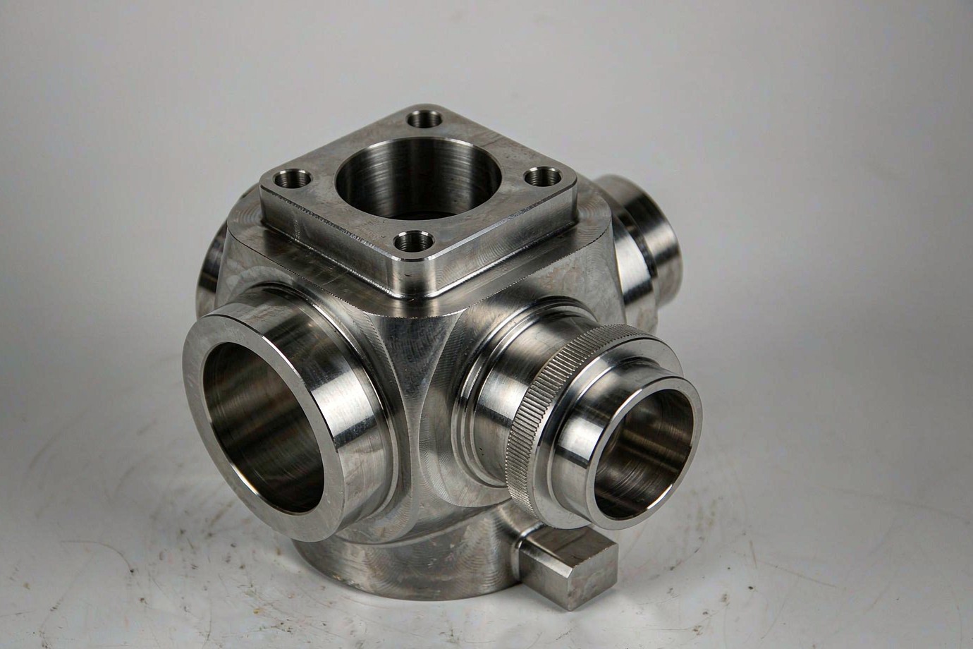
We machine valve bodies to your drawing — geometry, material certificate, sealing faces and bores, deburring and cleanliness are all controlled against the drawing and inspection plan. What we do not do is certify the finished valve: pressure rating and conformity to standards such as ASME B16.34, API 6D or EU PED are the assembler's responsibility, evaluated per project. A machined body is a precision component; a certified valve is a different, later step.
What a Machined Valve Body Is
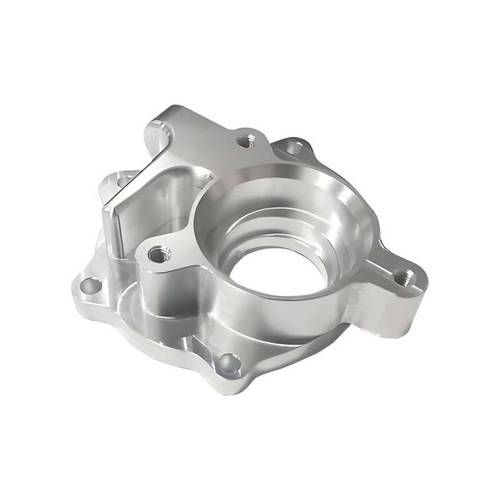
A valve body is the pressure-containing shell of a valve — the part that holds the flow path, the seat, the bonnet and the actuator interface. In CNC machining, the body starts as solid bar, plate or a near-net forging and is cut to the drawing: the flow bore, the port faces, the bonnet flange or threaded neck, and any mounting features.
Buyers usually come to a machining shop for one of two reasons: the production volume does not justify a casting tool, or the design needs tighter geometry and material control than casting comfortably gives. Both are valid; the trade-off is cost and lead time versus control and flexibility.
Machined vs Cast Valve Body
Both produce a body; the trade is control and flexibility against tooling cost. The table shows where each fits.
| Factor | Machined (solid / forging) | Cast |
|---|---|---|
| Best for | Low to medium volume, tight geometry | High volume, complex shape |
| Material control | Certified stock, full heat/lot traceability | Melt and heat controlled by the foundry |
| Lead time | Short; no tooling to wait for | Longer; pattern and tooling first |
| Geometry limit | Tool access and reach | Section thickness and draft angle |
| Cost driver | Cycle time per part | Tooling amortization across volume |
Common Valve Body Types We Machine
The body shape drives fixturing and access. The table lists the bodies most often machined from solid or forging, with the feature each one stresses most.
| Body type | Typical feature stressed | Machining note |
|---|---|---|
| Ball valve body | Spherical/cylindrical bore + seat pockets | Multi-face access; often 4/5-axis. |
| Gate valve body | Through bore + bonnet flange | Prismatic; flange flatness matters. |
| Globe valve body | Z or Y flow path | Internal passages; tool reach matters. |
| Check valve body | Compact bore + spring seat | Small, often turned features. |
| Butterfly valve body | Disc seat + wafer/lug faces | Large flat faces; thin walls. |
| 2-way / 3-way / multi-port | Port angle + intersecting bores | Datum strategy is the key risk. |
Critical Features and Where They Go Wrong
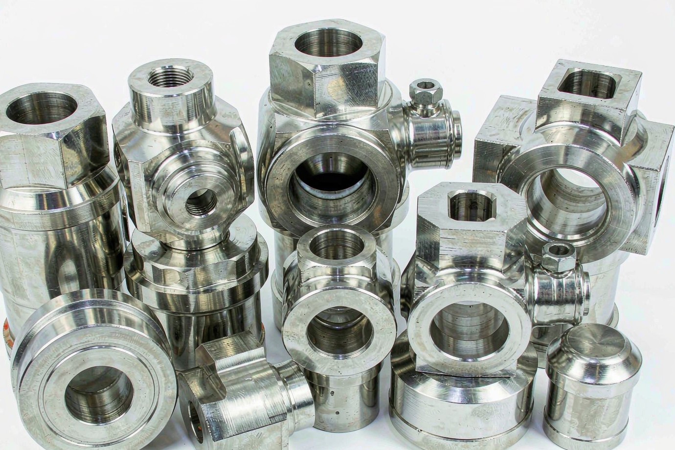
Most valve-body rejects trace back to a short list of features. Each is controlled as a critical-to-quality (CTQ) item, measured on a CMM and reported against the drawing.
Flatness and finish on the seat and bonnet face. Machined last, measured against datums.
Diameter and concentricity of the flow path; feature control frames, not a single number.
Between intersecting bores; thin sections deflect and chip — staged passes and support.
Bolt-circle position and face flatness control leak path at assembly.
Thread form and position; thread entry must be clean for assembly.
Reference datums for everything else; set first, hold through the run.
Machining controls geometry; it does not certify pressure. A body cut to drawing is a precision component. Pressure rating, hydrostatic and seat-leak testing, and conformity to ASME B16.34, API 6D or EU PED 2014/68/EU are the responsibility of the party that assembles, tests and releases the complete valve — evaluated per project, not offered as a uniform in-house service. State the intended service and any required standard on the drawing so the control plan can address it.
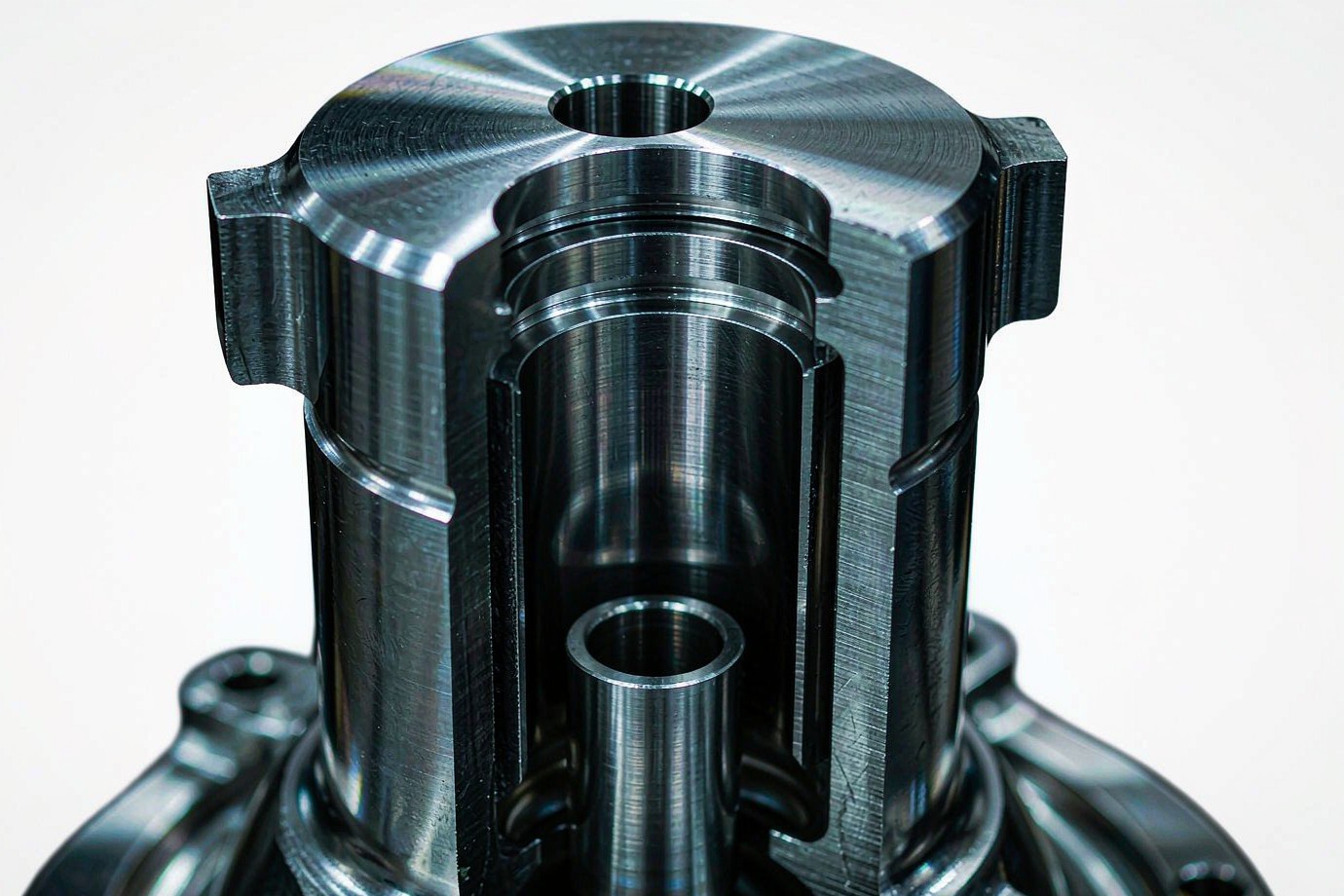
Which CNC Processes Are Used
Geometry, not axis count, decides the process. The goal is to hold datum consistency and reach internal features in fewer setups. Rotational features such as stems and threaded necks are produced on CNC turning equipment.
Prismatic bodies, flanges and flat faces where features are on accessible planes.
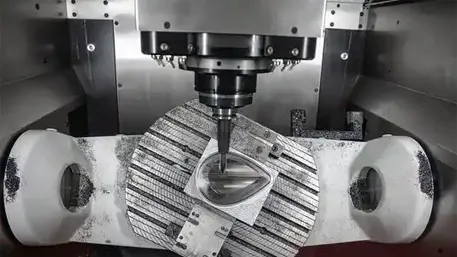
Multi-face bodies, angled ports and complex surfaces reached in fewer setups.
Rotational features such as stems, threaded necks and round bosses.
Mixed bodies done in one chucking to protect datum consistency.
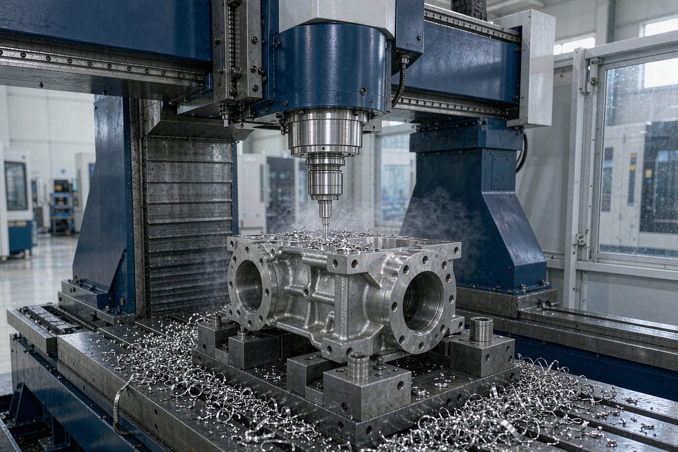
Materials We Machine for Valve Bodies
The material is confirmed from your drawing and its certificate before cutting. The list below is a capability range — not a statement that every grade is stocked for every order.
| Material family | Typical grades | Why it is chosen |
|---|---|---|
| Stainless steel | 304/304L, 316/316L | Corrosion resistance for water, food, general service. |
| Carbon steel | A105 / equivalent per drawing | Strength and cost for non-corrosive service. |
| Duplex / super-duplex | 2205, 2507 (per spec) | High strength + corrosion for offshore, chemical. |
| Nickel alloys | Inconel, Hastelloy (per spec) | High temperature and aggressive media. |
| Brass / bronze | Per drawing | Lower-pressure and instrument bodies. |
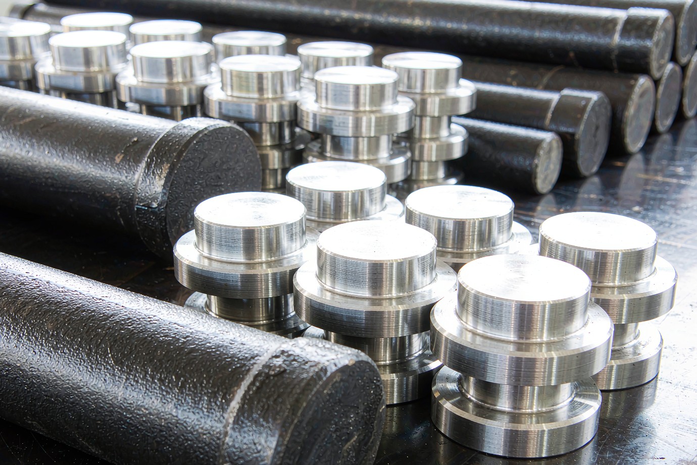
See the full material options and machining notes in our materials hub.
Tolerance and GD&T
Tolerance is not one number. It depends on geometry, wall thickness, datum strategy, workholding, tool wear and inspection — three practical tiers:
| Tier | Typical value | What it applies to |
|---|---|---|
| General | ±0.05 mm | Non-critical and cosmetic dimensions. |
| Controlled | ±0.01 mm | Features needing better-than-general control. |
| Qualified CTQ | ±0.005 mm | Sealing faces, bores, locating surfaces — CMM-confirmed. |
Deburring, Cleanliness and Inspection
For a part that sees fluid, what is removed after cutting matters as much as what is cut. Three controlled steps:
Edge breaking controlled to the drawing, with focus on internal passages, ports and thread entries.
Removal of cutting fluid, swarf and abrasives; level defined per project (food, pharma, oxygen service).
CMM on CTQ features, plus micrometers, bore gauges and roughness testers as the drawing requires.
We do not claim a part is burr-free in an absolute sense. Edge condition is controlled and inspected to the specified requirement — which is what matters in fluid service. An unqualified "burr-free" claim is not a controllable manufacturing statement.
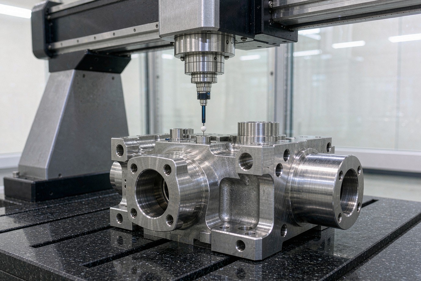
Our quality system and certificates are summarized on the quality certifications page.
From Prototype to Repeat Production
The workflow a buyer should expect, from drawing to documented release:
Material, datums, GD&T, thin walls and internal access reviewed before cutting.
Grade, condition and heat/lot confirmed against the material certificate.
Roughing controls load and heat; finishing brings CTQ features to the drawing.
Edge break and cleaning to the specified level for the intended service.
CMM inspection, material cert, dimensional report and CoC.
First-article where required; repeat runs follow the same plan.
Ready to turn a drawing into a validated prototype? Upload CAD / Request a Quote →
Where Machined Valve Bodies Are Used
Upstream and downstream bodies in stainless, duplex and nickel alloys.
General-service bodies where corrosion resistance and cost matter.
Corrosive-media bodies; material and cleanliness planned per media.
Steam and high-temperature bodies in specified alloys.
Corrosion-resistant bodies for demanding environments.
Small brass/steel bodies for measurement and control.
Valve Body RFQ Checklist
- 3D CAD model (STEP, IGES or native)
- 2D drawing with dimensions and GD&T
- Material grade and condition (e.g. 316L per the governing standard)
- Quantity and prototype-vs-production intent
- Critical tolerances and datum strategy
- Surface finish on sealing faces and bores
- Deburring and cleanliness level for the intended service
- Inspection and documentation requirements (EN 10204 3.1, FAI)
- Intended service and any referenced standard (ASME B16.34 / API 6D / PED)
- Application, annual volume and target delivery
Xiamen Goldcattle Plastic & Metal Products Co., Ltd. has provided custom machined parts since 1998, with 3-, 4- and 5-axis milling and turning across 100+ machines and six processes under one ISO 9001:2015 quality system, with AS9100- and ISO 13485-aligned frameworks.
Frequently Asked Questions
Can you CNC machine valve bodies from my drawing?
What materials can valve bodies be machined from?
What tolerance can a machined valve body hold?
Can a machined valve body be used for pressure service?
How are sealing faces and bores controlled?
What does deburring and cleanliness involve?
Which CNC processes are used for valve bodies?
What quality documents do I receive with machined valve bodies?
Can you machine prototypes and repeat production?
What should I send to get a valve body machining quote?
Do you make the complete valve or just the body?
Need Valve Bodies Machined From Your Drawing?
Send your CAD model and drawing. We can review the material and tolerances, run DFM, and define the machining, inspection and documentation plan for your program.
Upload CAD / Request a Quote →Free DFM review · Quote typically within 24 hours
Explore CNC Machining Capabilities →