
5 Axis CNC Machining Services
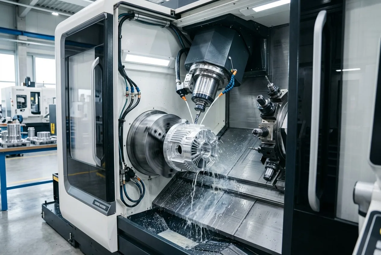
Simultaneous 5-axis and 3+2 indexed machining for impellers, multi-port housings, thin-wall structures and complex contoured components — engineered around fewer datum transfers, controlled feature relationships and dimensional results we can verify and document.
What You Are Actually Buying When You Buy 5-Axis Machining
Owning 5-axis machines is a prerequisite, not a capability. Any shop can publish a machine list. What determines whether your complex part arrives correct, repeatable and documented is the engineering work wrapped around the machine: how the process is chosen, how datums are held, how the toolpath is validated, and how the finished geometry is measured.
Correct process selection
We decide between 3-axis, 3+2 indexed and full simultaneous 5-axis based on your geometry, tolerance and volume — not on what keeps an expensive spindle busy.
Datum & fixture strategy
Interrelated critical features are machined under one common datum system wherever practical, so positional relationships do not depend on re-clamping accuracy.
Programming & simulation
Machine-specific post-processors, tool-axis control, holder-reach analysis and full kinematic simulation are completed before any material is cut.
Measurable verification
Surface profile, true position and runout are inspected on CMM against your datum scheme, with FAI and dimensional reports supplied on request.
The Questions Buyers Ask Before Placing a 5-Axis Order
These are the recurring evaluation points raised by engineers, procurement managers and supplier-quality teams sourcing complex machined components. Each links to the section of this page that answers it with method and evidence rather than adjectives.
When You Actually Need Simultaneous 5-Axis
Not every complex-looking part needs simultaneous 5-axis machining, and recommending it where 3+2 would satisfy the drawing increases programming cost and cycle time with no dimensional benefit. Below is the framework we apply during quotation.
3-Axis Machining
- Predominantly 2.5D pockets, bosses and prismatic features
- Features accessible from one or two orthogonal directions
- Moderate tolerances with no cross-face critical relationships
- Cost-sensitive parts where programming overhead matters
3+2 Indexed 5-Axis
- Multiple machined faces at fixed compound angles
- Inclined bores, angled sealing faces and ported housings
- Rotary axes position, then lock — full rigidity during cutting
- Access benefit of 5-axis without simultaneous programming cost
Simultaneous 5-Axis
- Continuously varying surfaces — impeller passages, blade profiles
- Tool axis must change during the cut to maintain contact and clearance
- Deep or side-entry cavities requiring shorter tools at an angle
- Surface continuity requirements that rule out zone-by-zone blending
Simultaneous 5-Axis vs 3+2 Indexed — Technical Comparison
| Capability | 3+2 Indexed Machining | Simultaneous 5-Axis Machining |
|---|---|---|
| Rotary-axis movement | Positioned and clamped, then stationary during cutting | Rotary and linear axes move together throughout the cut |
| Best suited to | Multi-face parts, inclined holes, multiple machining directions | Continuous surfaces, blades, impellers, dynamic tool-axis control |
| Tool orientation | Fixed for each operation | Continuously varying along the toolpath |
| Programming complexity | Moderate | High — requires tool-vector control and verification |
| Collision risk | Comparatively lower | Requires full kinematic simulation of machine, holder and fixture |
| Rigidity during cut | Higher — axes locked | Requires controlled feed and tool-axis smoothing |
| Surface continuity | Zone-by-zone; blending marks possible | Better continuity across compound curvature |
| Relative cost driver | Lower programming and validation cost | Higher programming, simulation and machine-rate cost |
| When we recommend it | Default for most multi-face precision components | Only where the geometry genuinely requires it |
Complex Geometries We Machine
We classify incoming work by geometric difficulty rather than by industry label, because the machining challenge — and therefore the process, fixture and inspection plan — follows the geometry.
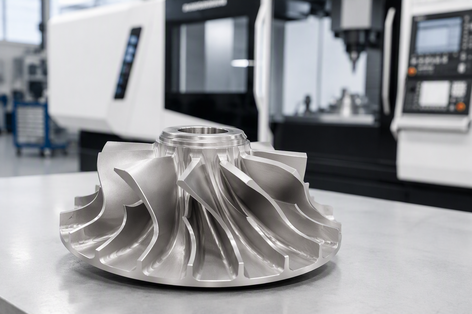
Continuous Contoured Surfaces
- Impellers, pump rotors and compressor wheels
- Turbine-style blades and vane profiles
- Mould inserts and fluid-flow surfaces
- Ergonomic and free-form metal structures
Challenge: tool access into narrow passages while maintaining surface continuity.
Approach: simultaneous tool-axis control with shorter effective tool length to limit deflection; roughing, semi-finishing and finishing separated with controlled stock.
Verification: CMM point measurement or scanning against a nominal CAD surface.
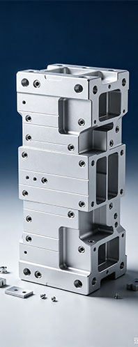
Multi-Face Related Features
- Valve bodies and hydraulic manifolds
- Multi-port housings and sensor enclosures
- Robotic joints and optical mounts
- Complex brackets with cross-face tolerances
Challenge: positional relationships between features on different faces.
Approach: 3+2 indexing under one datum system so cross-face position does not depend on re-clamping.
Verification: CMM datum alignment with true-position reporting.
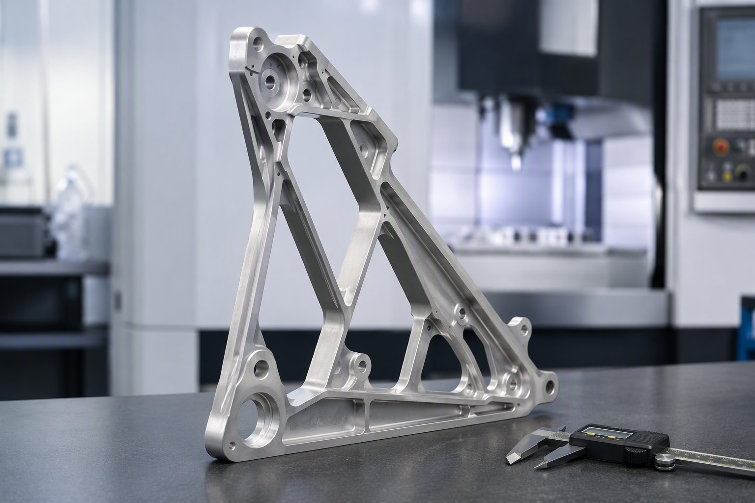
Thin-Wall & Lightweight Structures
- High material-removal structural components
- Deep-pocket housings with thin ribs
- Lightweight frames and aerospace-style structures
Challenge: distortion from clamping load and residual stress release.
Approach: balanced roughing, stress-relief between stages where required, staged finishing with reduced depth of cut, and supportive fixturing.
Verification: flatness, profile and wall-thickness inspection after final stage.
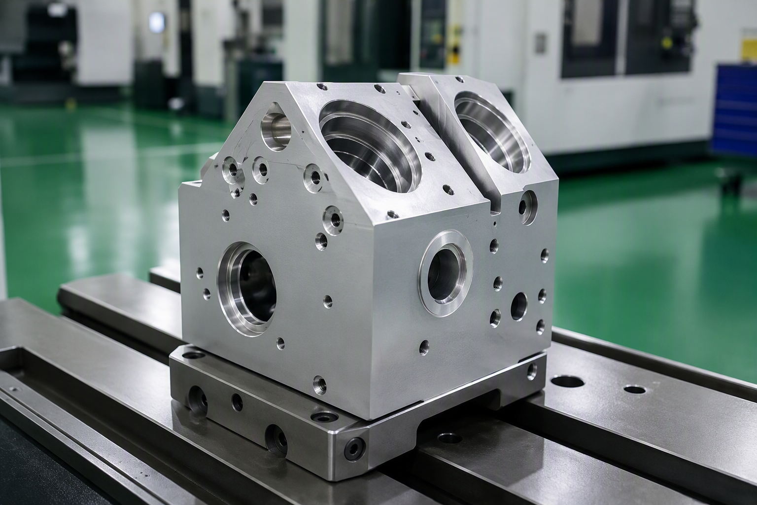
Compound Angles & Restricted Access
- Compound-angle and cross-drilled holes
- Inclined threaded ports and sealing faces
- Deep cavities with limited tool access
- Internal blending surfaces and curved channels
Challenge: reaching features without long, deflection-prone tooling.
Approach: part orientation via rotary axes so shorter, more rigid tools can be used at the required attitude.
Verification: CMM position and angle measurement; gauge inspection on threaded ports.
Datum and Fixture Strategy — Where Complex Parts Are Won or Lost
Most dimensional problems on complex machined parts are not caused by the cutting itself. They are caused by what happens between operations: every re-clamp introduces locating error, datum-transfer error, clamping distortion and operator variation. The value of multi-axis machining is not simply speed — it is machining more interrelated critical features within one coordinate system.
We read your GD&T datum structure first and build the fixture around it, rather than machining to a convenient shop reference and hoping the relationships hold.
Features carrying tolerance to each other are grouped into the same setup wherever geometry and clamping allow.
Clamp position and force are planned against wall thickness and stiffness to avoid machining a part in a distorted state.
Roughing leaves controlled stock; where material or removal ratio warrants it, stress relief is scheduled before finishing.
Where applicable, on-machine probing re-establishes the work coordinate system so the program cuts to the actual part, not the assumed position.
If a second setup is unavoidable, we define which features it carries and how the datum is re-established — and state it in the review notes.
Five-Axis Programming and Collision-Control Workflow
This is the difference between owning 5-axis machines and having 5-axis manufacturing capability. Every simultaneous 5-axis program passes through the following sequence before a tool touches your material.
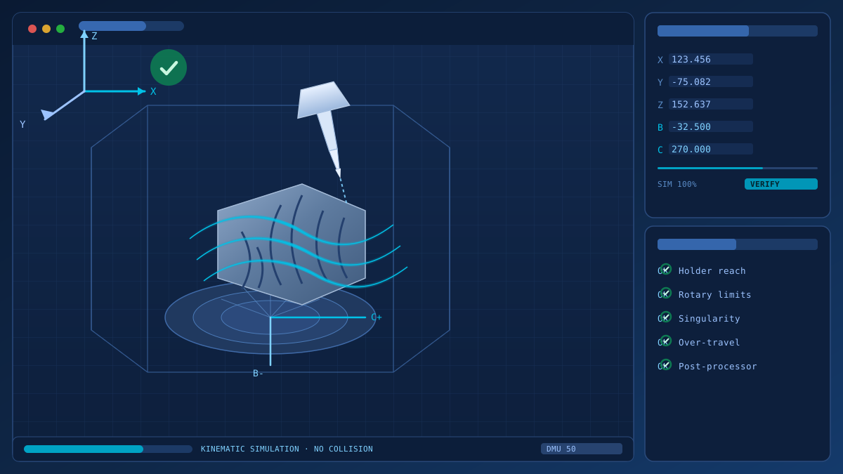
Technical controls applied
- Tool-centre-point (TCP) control
- Tool-vector smoothing to avoid surface witness marks
- Lead and tilt angle optimisation for contact conditions
- Holder and shank clearance verification
- Rotary-axis limit and singularity management
- Retract and linking strategy between passes
- Machine-specific post-processor per platform
- Remaining-stock verification before finishing
Why each machine needs its own post-processor
Our 5-axis platforms differ in kinematics, rotary configuration and control system. A program validated on one machine is not automatically safe on another. Each platform runs its own verified post-processor and simulation model, and jobs are not moved between machines without re-validation.
This is why we ask for your 3D model rather than only a 2D drawing — a validated simultaneous 5-axis program cannot be built reliably from a flat print alone.
The 5-Axis Platforms We Run
Equipment is the input, not the offer. We list our platforms so you can assess envelope and process fit — not as the reason to place an order. Configurations below reflect our installed machines; exact spindle, control, tool-magazine and probing specifications are confirmed in writing at quotation and available for audit.
DMG MORI DMU 50
- Type
- Universal milling centre, swivel rotary table
- Axis travel
- X 650 × Y 520 × Z 475 mm machine max
- Rotary axes
- B-axis swivel + C-axis rotation
- Typical work
- Impellers, contoured surfaces, multi-face housings
- Spindle / control
- Confirmed at quotation
Mazak 5-Axis Machining Centre
- Type
- 5-axis machining centre, Mazatrol / CNC control
- Axis travel
- Model-specific — confirmed at quotation
- Rotary axes
- Tilting rotary configuration
- Typical work
- Multi-face precision components, angled bores, repeat production
- Spindle / control
- Confirmed at quotation
3-Axis & 4-Axis Milling Centres
- Role
- Prismatic features, secondary operations, cost-appropriate work
- Why it matters
- Lets us route features to the cheapest process that meets the drawing
Turning, EDM & Grinding Support
- Role
- Rotational features, hardened detail, fine surface finishing
- Sourcing
- Selected specialist operations are performed by audited partners under Goldcattle process control and responsibility
Machine Maximum Is Not Your Working Envelope
A common sourcing error is to take a manufacturer's catalogue envelope as the size of part a shop can actually machine. Once fixturing, tool length, rotary tilt and collision clearance are included, the usable envelope is smaller — and it changes with part shape.
Machine maximum
The theoretical mechanical envelope published by the machine builder. Useful for elimination only — never quote against it.
Recommended working envelope
The range in which we routinely produce stable, repeatable results with normal fixturing and tooling. This is what we quote against.
Engineering-review range
Parts near the limits, with long tooling, extreme tilt attitudes or unusual fixturing. Feasible in some cases, but confirmed only after model review.
Materials We Machine on 5-Axis
This list reflects materials we hold established cutting parameters, tooling and process experience for on multi-axis work — not everything the machines are theoretically capable of cutting.
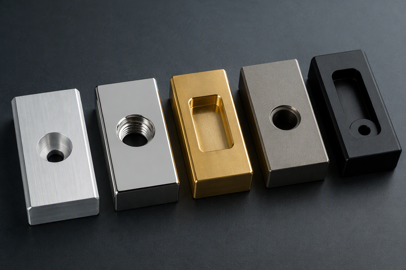
| Material | Typical 5-axis applications | Main process considerations |
|---|---|---|
| Aluminium 6061 / 7075 | Impellers, housings, lightweight structures | Thin-wall distortion, workholding strategy, chip evacuation in deep passages |
| Stainless steel 303 / 304 / 316 / 17-4PH | Instrument components, valve and equipment parts | Heat generation, tool wear, cutting-force control on slender features |
| Titanium Ti-6Al-4V | High strength-to-weight components | Heat concentration, tool-life management, controlled engagement — reviewed per project |
| Tool steel / hardened steel | Mould inserts, high-wear detail | Hardness, finishing strategy, whether grinding or EDM is a better route |
| Brass & copper | Fluid-control and electrical components | Burr control, surface protection and handling |
| PEEK & engineering plastics | Medical and semiconductor equipment parts | Thermal expansion, machining-induced stress, measurement temperature control |
Accuracy, Thermal Control and Achievable Tolerances
Machine specification and part tolerance are different things. A machine's positioning accuracy describes the platform; the tolerance held on your part additionally depends on geometry, material, fixture rigidity, tool length, thermal state, cutting strategy and measurement method. The table below states what we hold in practice on multi-axis work.
| Characteristic | Standard capability | Enhanced capability | Engineering review required |
|---|---|---|---|
| Linear dimensions (<100 mm) | ±0.05 mm | ±0.02 mm | Tighter than ±0.01 mm |
| Linear dimensions (100–300 mm) | ±0.08 mm | ±0.03 mm | Tighter than ±0.02 mm |
| Bore diameter | ±0.02 mm | ±0.01 mm | H6 or tighter |
| True position (hole pattern) | ∅0.05 mm | ∅0.02 mm | Tighter than ∅0.015 mm |
| Surface profile (contoured) | 0.05 mm | 0.02 mm | Tighter than 0.015 mm |
| Runout / concentricity | 0.02 mm | 0.01 mm | Tighter than 0.008 mm |
| Surface roughness (milled) | Ra 1.6 µm | Ra 0.8 µm | Ra 0.4 µm or finer |
| Wall thickness (thin-wall) | ±0.10 mm | ±0.05 mm | Below 0.8 mm nominal wall |
What the machine platform contributes
- Rigid machine structure and cast bed
- Direct measuring systems on linear axes
- Cooled rotary-table bearings and integrated cooling concept
- Rotary-axis encoder feedback
- Thermal compensation functions in the control
What our process contributes
- Temperature-stabilised inspection environment for critical measurement
- Tool-life monitoring and scheduled tool replacement on tolerance-critical features
- Warm-up cycles before precision finishing runs
- Controlled finishing stock and separate finishing passes
- First-article verification before batch release
Inspection and Verification of Complex 5-Axis Parts
Contoured multi-axis parts cannot be validated with callipers and micrometers alone. Surface profile, cross-face position and blade geometry require coordinate measurement referenced to your datum scheme.
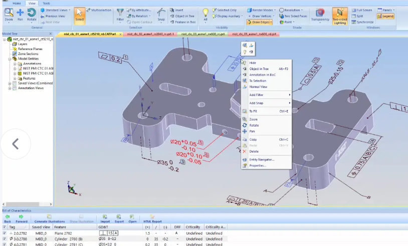
| Feature | Inspection method | Typical output |
|---|---|---|
| Complex surface profile | CMM point measurement or scanning vs CAD nominal | Deviation report / colour map |
| Blade and vane contour | CMM or optical scanning | Profile deviation per section |
| Hole position across faces | CMM with datum alignment | True-position report |
| Bore diameter | Bore gauge or CMM | Dimensional report |
| Runout / concentricity | Indicator setup or CMM | Dimensional report |
| Surface roughness | Profilometer | Ra value per specified area |
| Threaded ports | Thread gauges + positional inspection | Go/no-go + position |
| Thin-wall thickness | Ultrasonic or CMM probing | Thickness map at defined points |
Documentation available
- First Article Inspection (FAI) report
- Full dimensional report against balloon drawing
- CMM output referenced to customer datums
- Customer-specified measurement points on request
- Material certificates and traceability
- Surface-treatment certificates where applicable
Answers to the usual sourcing questions
- Do you provide FAI? Yes, on request; standard for new part numbers.
- Point measurement or scanning? Point measurement by default; scanning where continuous profile evaluation is specified.
- Can we specify the points? Yes — supply the balloon drawing or point list.
- 100% inspection of critical dimensions? Available; defined per part and priced transparently.
- Is reporting chargeable? Basic dimensional reporting is included; full CMM programmes and 100% schemes are quoted separately.
Is 5-Axis Machining Right for Your Project?
Use this as a pre-RFQ filter. It will save you time whether or not we end up quoting the work.
Strong fit
- Multiple machined faces with tolerances referenced to each other
- Continuous contoured surfaces — impellers, blades, flow passages
- Compound-angle holes and inclined sealing faces
- Current 3-axis route needs too many setups
- Deep cavities that force long, deflecting tools
- Existing supplier shows datum-transfer inconsistency
- Prototype now, repeat production later
May not need simultaneous 5-axis
- Predominantly simple 2.5D pockets and prismatic features
- All features accessible in orthogonal directions
- 3+2 indexing already satisfies the drawing
- Wide tolerances with no cross-face relationships
- Very low quantity with simple geometry and tight budget
- Part is fundamentally rotational — turning may be the better route
Requires specific review
- Parts beyond the recommended working envelope
- Ultra-thin-wall structures below 0.8 mm nominal
- Extremely deep or narrow flow passages
- Difficult or unfamiliar alloys
- Implantable medical or flight-critical aerospace parts
- Profile requirements tighter than 0.015 mm
- Parts exceeding table load limits
- Work better suited to mill-turn than milling
5-Axis Machining Case Studies
Representative projects. Figures describe the specific parts shown and are not a guarantee of identical results on different geometry, material or volume.
Compressor Impeller, Aluminium 7075
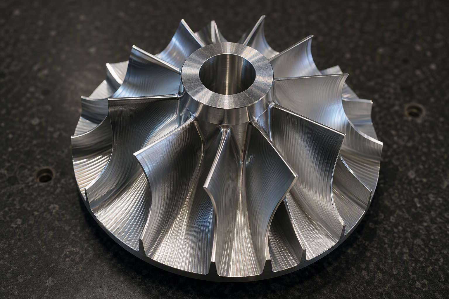
| Challenge | Narrow blade passages restricting tool access; continuous hub-to-blade surface required without blending marks |
| Process | Simultaneous 5-axis roughing, semi-finishing and finishing with continuous tool-axis control |
| Method detail | Shorter effective tool length via part tilt to reduce deflection; separate leading/trailing-edge finishing pass |
| Result | Surface profile held within 0.03 mm to CAD nominal; finish Ra 0.8 µm on flow surfaces |
| Verification | CMM scanning against nominal surface, section-by-section deviation report |
| Volume | Prototype through low-volume batch |
Multi-Port Hydraulic Housing, Aluminium 6061
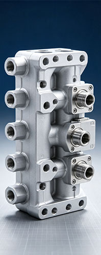
| Challenge | Angled bores on five faces with position tolerance referenced across faces; previous route used four setups |
| Process | 3+2 indexed machining under one datum system — simultaneous motion not required by the geometry |
| Method detail | Fixture built to the drawing's datum structure; on-machine probing to re-establish WCS |
| Result | Setups reduced 4 → 2; cross-face true position improved from ∅0.05 mm to ∅0.02 mm |
| Verification | CMM datum alignment with true-position reporting on all ports |
| Volume | Repeat production batches |
Thin-Wall Structural Component, Aluminium
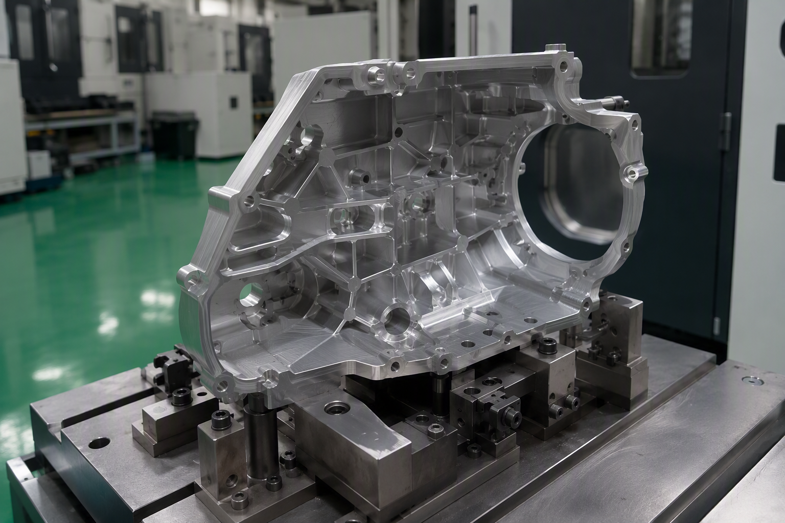
| Challenge | High material removal from solid billet with 1.2 mm nominal walls; earlier supplier saw distortion after finishing |
| Process | Balanced roughing sequence, intermediate stress relief, staged finishing with reduced radial engagement |
| Method detail | Sacrificial support tabs retained until final pass; clamping force reduced for finishing |
| Result | Flatness held within 0.05 mm; wall thickness within ±0.05 mm across mapped points |
| Verification | Flatness and profile inspection plus wall-thickness mapping post-machining |
| Volume | Prototype validation through pilot batch |
From Prototype to Repeat Production
The same programs, fixtures and inspection method carry forward from first article to series production, so you are not re-qualifying a new process when volume increases.
What stays constant across volume
- Validated CAM programs and post-processors
- Fixture design and clamping scheme
- Datum strategy and work-coordinate setup
- Inspection programme and reporting format
What we adjust as volume grows
- Cycle-time optimisation once geometry is proven
- Tool-life monitoring intervals and sister tooling
- Sampling plan versus 100% critical-dimension inspection
- Whether a feature is better routed to 3-axis or turning
Frequently Asked Questions
What is simultaneous 5-axis machining, and how is it different from 3+2?
Will my part be completed in one setup?
What is the maximum part size you can machine?
Which materials do you machine on 5-axis?
Can you machine impellers and bladed components?
Can you manufacture orthopaedic implants or flight-critical aerospace parts?
What tolerances can you hold on a contoured surface?
Do you provide CMM reports and first article inspection?
Is 5-axis machining more expensive than 3-axis?
Which files do you need to quote?
Can you review a machining process another supplier is struggling with?
How do you control collision risk in simultaneous 5-axis programs?
Submit a Complex Part for Process Review
Upload your 3D model and 2D drawing. Our engineering team reviews part size, rotary-axis access, tool reach, fixture strategy, material, tolerance and inspection requirements before recommending simultaneous 5-axis, 3+2 indexed or an alternative process. You receive a process recommendation, not just a price.