"Will My Part Fit Your Machine Once Fixtures and Tilt Are Accounted For?"
Machine Maximum vs Working Envelope vs Engineering Review Range
A common sourcing error is to take a manufacturer's catalogue envelope as the size of part a shop can actually machine. Once fixturing, tool length, rotary tilt attitude and collision clearance are included, the usable envelope is smaller — and it changes with part shape. This page explains the three envelope tiers we use, how we determine fit before quoting, and what information we need from you to give an accurate answer.
The Short Answer
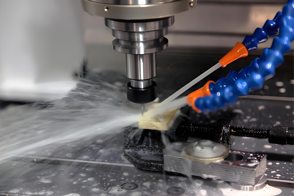
We distinguish three envelope levels, and we quote against the middle one (Recommended Working Envelope), not against the catalogue maximum:
- Machine Maximum: the theoretical mechanical travel published by the machine builder. Useful for elimination only — never quote against it.
- Recommended Working Envelope: the range in which we routinely produce stable, repeatable results with normal fixturing and tooling. This is what we quote against.
- Engineering-Review Range: parts near the limits, requiring long tooling, extreme tilt attitudes or unusual fixturing. Feasible in some cases but confirmed only after 3D model review.
The gap between Machine Maximum and Recommended Working Envelope is typically 20–40% depending on part geometry. On 5-axis machines this gap is larger than on 3-axis machines because rotary tilt consumes additional clearance that would otherwise be available for the part itself.
The Three Envelope Tiers Explained
Understanding which tier your part falls into prevents the most common capacity mismatch: a part that fits within the catalogue maximum but cannot actually be machined because fixture + tilt + tooling consume the remaining space.
Tier 1: Machine Maximum
The theoretical mechanical envelope from the machine builder's specification sheet.
- X × Y × Z axis travels at full stroke (no workpiece)
- Maximum rotary-axis swing range (no part mounted)
- Maximum table load capacity (static, centred load)
- Spindle-nose-to-table distance at extreme positions
Why you cannot quote against it
- Assumes zero fixture height, zero tool overhang, no tilt attitude
- Does not account for holder clearance during angled cuts
- Does not account for probe access or clamping space
- A part at 95% of machine maximum will almost certainly not be machinable in practice
Tier 2: Recommended Working Envelope
The range where we routinely deliver stable, repeatable results with standard fixturing and tooling.
- Accounts for typical fixture height (30–80 mm depending on part type)
- Accounts for reasonable tool overhang (3× diameter for standard tools; more for deep-reach features)
- Accounts for common tilt attitudes (±15° to ±25° on rotary axes for most 3+2 work)
- Includes collision margin between holder/table and machine structure at tilted positions
- Allows space for clamp access, probing approach and chip evacuation
This is what we quote against
- If your part fits within this tier with normal fixturing, we quote confidently without special review
- Cycle time and cost estimates based on proven parameters within this range
- First-article lead time follows our standard schedule (7–15 days for prototype)
Tier 3: Engineering-Review Range
Parts near or beyond the recommended working envelope that may still be feasible under specific conditions.
- Requires long-reach tooling (stick-out >5× diameter) with associated deflection management
- Extreme tilt attitudes approaching rotary-axis limits (>±30° on one or both axes)
- Unusual fixturing requirements (extended tombstone fixtures, vacuum chucks for thin parts, multi-part setups)
- Near table load limit or requiring off-centre loading analysis
- Deep cavities where holder clearance is the binding constraint rather than axis travel
How we handle it
- 3D model review required before quotation — we will not quote blind for tier-3 parts
- If feasible, we quote with extended lead time and/or higher cost reflecting risk mitigation measures
- If not feasible on our current platforms, we will say so explicitly and suggest alternatives (different process, different supplier, design modification)
What Consumes Your Usable Envelope (Beyond Part Size)
The difference between your part's bounding-box dimensions and the space it actually occupies on the machine is often surprising. These six factors consume envelope on every 5-axis job.
| Factor | What It Consumes | Typical Amount (varies by part) | Can It Be Reduced? |
|---|---|---|---|
| Fixture base height | Z-height below the part bottom | 20–80 mm (soft jaws: 20–40 mm; dedicated fixture: 40–80 mm) | Yes: lower-profile fixture design; direct table mounting for flat parts |
| Tool overhang (stick-out) | Space above the part for cutter engagement plus holder clearance | Varies: short tools (2–3× dia) need less; deep-cavity tools (6–10× dia) need significantly more Z-space | Yes: 5-axis tilt allows shorter effective reach for the same feature depth |
| Rotary tilt attitude | As the part tilts, its effective height in Z increases and its X/Y position shifts relative to the spindle | A part tilted 25° gains ~15% effective height; tilted 45° gains ~41% | Sometimes: reorient the part datum to minimise tilt angle for critical operations |
| Holder clearance cone | The tool holder sweeps a cone around the cutter path as the machine tilts; nothing can occupy this volume | Diameter = holder diameter + 2× safety margin (typically 3–5 mm per side) | Limitedly: smaller-diameter holders (taper-shank vs collet-chuck); shorter gauge-length holders |
| Clamp access space | Room for clamp mechanism (toggle clamps, strap clamps, hydraulic cylinders) and operator/tool access | 15–40 mm around the part perimeter depending on clamp type | Yes: integrated fixture clamps; vacuum chucking eliminates peripheral clamps entirely |
| Probe approach | Clearance for touch-trigger probe to reach datum features and inspection points without collision | 10–25 mm additional beyond cutting envelope at probed locations | No: probing clearance is a safety requirement, not negotiable |
Our Platform Envelopes: What We Publish and What We Quote Against
We publish machine model and travel so you can assess basic fit. Exact installed configuration (spindle option, control version, tool magazine size, probing equipment) is confirmed in writing at quotation.
DMG MORI DMU 50
| Type | Universal milling centre, swivel rotary table (B + C axes) |
| Axis travel (machine max) | X 650 × Y 520 × Z 475 mm |
| Rotary axes | B-axis swivel + C-axis rotation |
| Table diameter | Ø500 mm (typical working: Ø350–400 mm incl. clamp) |
| Max part weight | 400 kg (centred, distributed load) |
| Spindle / control | Confirmed at quotation |
Mazak 5-Axis Platform
| Type | 5-axis machining centre, tilting rotary configuration |
| Axis travel (machine max) | Model-specific — confirmed at quotation |
| Rotary axes | Tilting rotary (specific config per installed machine) |
| Typical applications | Multi-face precision components; angled bores; repeat production |
| Spindle / control | Confirmed at quotation |
Feature-Level Size Guidelines
Beyond overall part size, individual features have practical limits that affect whether they can be machined reliably. Use these as pre-RFQ filters.
| Feature Type | Preferred Range | Risk Zone (Needs Review) | Why It Matters |
|---|---|---|---|
| Deep pocket depth | Up to 3× tool diameter | > 5× tool diameter | Long tools deflect and chatter; surface finish degrades non-linearly with depth |
| Internal corner radius | ≥ 0.5× pocket depth where possible | Very small radius in deep cavity | Small radius forces small cutter = weak, slow, short tool life |
| Drilled hole depth | Up to 5× drill diameter (standard) | > 10× drill diameter | Chip evacuation fails; drill wanders; straightness suffers |
| Thin-wall thickness | Aluminium: ≥1.0 mm; Steel: ≥1.5 mm | < 0.8 mm nominal wall | Vibration and clamping distortion increase exponentially below threshold |
| Impeller passage width | ≥ 12 mm (allows Ø8–10 mm ball tool with clearance) | < 8 mm (approaches minimum tool diameter limit) | Narrow passages restrict tool diameter, forcing longer tools or multiple passes |
| Blade trailing-edge thickness | ≥ 0.5 mm (aluminium); ≥ 0.8 mm (steel/titanium) | < 0.3 mm (extremely fragile; prone to tearing or breakage) | Thin trailing edges tear under excessive lead angle or high feed engagement |
| Flatness over large area | Use functional flatness only where needed; specify local datum pads | Tight flatness (>0.02/300 mm) over large unsupported area | Residual stress release after machining distorts large flat surfaces unpredictably |
Frequently Asked Questions
What is the largest part you can machine?
My part is close to the machine limit — should I even send it?
Do you charge extra for parts near the envelope limit?
What file format do you need for envelope checking?
Not Sure if Your Part Fits Our Machines?
Upload your 3D model. We will run it through our envelope analysis — fixture space, tilt clearance, tool reach, table load — and give you a definitive yes/no/maybe with reasoning, usually within 24 hours.
STEP / IGES / Parasolid accepted. No obligation. Confidentiality guaranteed.