"My Supplier's Multi-Face Positional Relationships Drift Between Batches"
The Root Cause and How We Control It
The most common dimensional failure mode on complex machined parts is not caused by the cutting accuracy of the machine. It is caused by what happens between operations: every re-clamp introduces locating error, datum-transfer error, clamping distortion and operator variation. This page explains our datum and fixture strategy — the engineering work that determines whether your part's critical features stay related, batch after batch.
The Short Answer
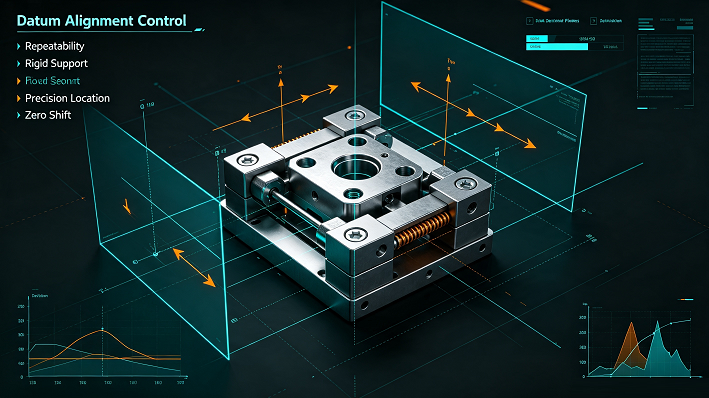
Multi-face positional drift between batches is almost always caused by datum transfer across multiple setups, not by machine positioning inaccuracy. Our control approach has six layers:
- Datum-scheme-first review: we read your GD&T datum structure before designing any fixture, and build the fixture around it — not the reverse.
- Feature grouping: features that carry tolerance to each other are machined under one common datum system wherever geometry allows.
- Clamping-load control: clamp position and force are planned against wall thickness and stiffness to avoid machining a distorted part.
- In-process probing: on-machine touch-probe re-establishes the work coordinate system so the program cuts to the actual part position, not an assumed one.
- Stress management: roughing leaves controlled stock; stress relief is scheduled before finishing where material or removal ratio warrants it.
- Documented secondary setups: if a second setup is unavoidable, we define which features it carries, how datum is re-established, and state it in the review notes.
Why Positional Relationships Drift: The Mechanics of Error Accumulation
Understanding the error chain is the first step to controlling it. Each re-clamping operation introduces small errors that are individually negligible but compound across setups and batches.
The Error Chain Per Setup
| Error source | Typical magnitude (well-controlled shop) |
| Locating-surface variation | 0.002–0.008 mm |
| Fixture wear / debris | 0.001–0.005 mm |
| Clamping-force distortion | 0.003–0.015 mm (thin-wall parts higher) |
| Thermal drift between ops | 0.002–0.010 mm |
| Operator loading variation | 0.001–0.006 mm |
| Combined per setup (RSS) | 0.005–0.022 mm |
These figures represent best-practice ranges from published machining tolerance studies. Actual values depend on part geometry, fixture design, material and environmental control.
Why It Shows Up Between Batches, Not Within One Batch
- Within a batch: the same fixture, same operator sequence, same thermal profile → errors are repeatable and often self-cancelling if the datum strategy is consistent.
- Between batches: fixture is removed and re-installed; different operator may load; material batch may differ (residual stress pattern changes); ambient temperature may shift → the same small per-setup error now has a different baseline each time.
- The symptom you see: batch 1 passes incoming inspection; batch 2 shows hole patterns shifted by 0.01–0.03 mm relative to datum A; batch 3 shifts in a different direction. The machine hasn't drifted — the datum establishment has.
Our Six-Layer Datum and Fixture Strategy
Each layer below addresses a specific error source in the chain. Together they form the control system that keeps your multi-face features related within tolerance, batch after batch.
Datum-Scheme-First Review
We read your GD&T datum structure (ASME Y14.5 / ISO 5459) before designing any fixture or writing any toolpath. The primary datum is selected based on functional assembly interface — not on which face is easiest to clamp.
- The drawing's datum A becomes our machining datum A wherever physically practical
- If the drawing datum is ambiguous or unstable for fixturing, we raise a DFM query before quoting — we do not guess and hope
- Datum feature must be accessible, rigid, and unlikely to change across operations (no thin walls, no raw-stock faces as primary datums)
Feature Grouping Under Common Datum
Features that carry geometric tolerance to each other (position, runout, concentricity, profile) are grouped into the same setup wherever geometry and clamping allow.
- Cross-face hole patterns: all holes referenced to the same datum bore in one clamping if reachable
- Sealing faces perpendicular to bore axes: finished in the same setup as the bore where possible
- Related features split across unavoidable setups: the transfer path is documented with expected error budget
Clamping-Load Control
Clamp position and force are engineered against the part's local stiffness, not left to operator judgement.
- Clamp contact points positioned away from thin-wall regions and near supported areas
- Clamping force specified in the setup document (torque wrench or pneumatic setting)
- Maximum clamping pressure calculated against wall deflection limits for thin-wall parts
- Soft jaws or dedicated fixtures with matched contact surfaces to distribute load evenly
In-Process Probing
On-machine touch-trigger probing re-establishes the work coordinate system at critical points so the program cuts to the actual part position.
- Probing after each index operation to confirm datum re-establishment before cutting resumes
- Mid-run probing of critical dimensions to detect thermal drift or tool wear before scrap occurs
- Automatic offset compensation when probe data deviates from nominal (within control limits)
- Probe results logged for traceability and trend analysis across batches
Stock and Stress Management
Roughing leaves controlled stock; finishing removes a predictable amount. Where material or removal ratio warrants it, stress relief is scheduled between stages.
- Balanced roughing toolpaths to minimise asymmetric residual stress
- Controlled semi-finishing stock (typically 0.15–0.30 mm depending on material) for predictable finish pass
- Natural ageing or thermal stress relief scheduled for high removal-ratio parts (>60% volume removed)
- Sacrificial support tabs retained until final pass to maintain stiffness during finishing
Documented Secondary Setups
When a second setup is genuinely unavoidable (back-side features, clamping-face access), we do not hide it.
- Which features are carried in the secondary setup, explicitly listed
- How datum is re-established (probed features, locator surfaces, alignment method)
- Error budget for the datum transfer (expected range, inspection verification point)
- Stated in the RFQ review notes so you can evaluate the risk before approving
Fixture Approaches We Use, and When
Not every part needs a dedicated custom fixture. The right fixture choice depends on volume, tolerance, geometry and stage of production.
Soft Jaws / Modular Fixtures
Machinable soft jaws or modular vise systems with custom inserts.
- Best for: prototype and low-volume parts (1–50 pcs), prismatic geometries, moderate tolerances (±0.05 mm typical)
- Advantage: low tooling cost, fast to modify for design iterations
- Limitation: repeatability depends on jaw-seat condition and operator loading consistency
Dedicated Precision Fixtures
Custom-machined aluminium or steel fixtures with hardened locators, dowel pins and clamps.
- Best for: production volumes (50+ pcs), tight tolerances (∅0.02–0.05 mm position), critical multi-face relationships
- Advantage: highest repeatability; poka-yoke design prevents incorrect loading
- Limitation: higher upfront cost; lead time for fixture fabrication
Vacuum / Magnetic Workholding
Vacuum chucks or magnetic tables for thin-wall or large flat parts.
- Best for: thin-wall parts where mechanical clamping would cause distortion; large flat plates; low-clamping-force materials
- Advantage: uniform holding force over entire contact surface; zero point-load distortion
- Limitation: requires sufficient flat contact area; limited holding force for heavy cutting
GD&T Datum Principles That Affect Your Part
How the drawing defines datums directly controls how accurately we can hold cross-face relationships. These principles from ASME Y14.5 and ISO 5459 affect every multi-setup part we machine.
| Principle | What It Means for Your Part | Common Mistake |
|---|---|---|
| 3-2-1 Locating Principle | The primary datum contacts at 3 points, secondary at 2, tertiary at 1 — constraining all 6 degrees of freedom without over-constraining | Using 4+ contact points on the primary datum creates indeterminate loading and repeatability variation |
| Datum Precedence Order Matters | The A→B→C sequence in the feature control frame defines how the tolerance zone is established; swapping the order changes the result | Treating datum A, B and C as interchangeable references |
| Datum Feature Stability | The datum feature must be stable under clamping force and unchanged across operations — large flat faces, bearing journals, finished bores | Using a raw-stock face, thin wall or temporary feature as the primary datum |
| Functional Datums Over Convenient Ones | Datums should reflect how the part assembles and functions in service, not which face is easiest to locate on the machine | Machining from a convenient shop reference and hoping the relationships hold at assembly |
| Datum Feature Must Be Finished First | If a datum bore or surface will be machined later, it cannot reliably serve as a datum for earlier operations | Machining features relative to a datum that gets recut or modified in a subsequent operation |
What "One Setup" Honestly Means
We do not claim that every operation on every part is completed without repositioning. That would not be accurate, and you would correctly distrust any supplier who made that claim unconditionally.
What we commit to: interrelated critical features are machined under one common datum strategy wherever practical. Clamping faces, back-side features and certain finishing operations may still require a secondary setup. Where a secondary setup is needed, we plan how the datum is re-established, quantify the expected transfer error, and state it in the review notes — so you can make an informed decision before approving the process.
Frequently Asked Questions
My current supplier's parts pass individual dimension checks but fail assembly. Is this a datum problem?
How much does a custom fixture cost, and when is it worth it?
Can you work with my existing datum scheme, or do you need to change it?
What happens if I don't specify GD&T datums on my drawing?
Seeing Positional Drift on Your Current Parts?
Send us your drawing plus the last three CMM reports showing the drift pattern. Our engineering team will analyse the datum strategy, identify the likely root cause, and tell you honestly whether our approach would improve it — before you commit to anything.
Confidential evaluation. NDA available on request. Response within 1–2 business days.