
A CNC prototype is a functional part machined directly from your CAD model in production-grade metals or engineering plastics. This guide explains what a CNC prototype is, when it is the right choice, how the process works, what it can actually validate, and how prototypes move into production — without the marketing shortcuts.
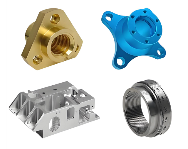
CNC prototype at a glance
A short summary for engineering and procurement. For commercial capability (machine types, materials list, tolerance, lead time), see the companion Custom CNC Prototype Parts page.
Need a CNC prototype for your project?
This guide explains the technology. The companion page handles the commercial side: machine capability, exact material list, tolerance bands, inspection and quoting. Send your CAD and the test the prototype must pass.
What is a CNC prototype?
A CNC prototype is a part produced by computer-controlled machining directly from a digital CAD design. The machine removes material from a solid block, bar or billet to create the part, rather than adding material (as in 3D printing) or forming it in a closed tool (as in injection molding).
Because CNC prototypes come from the same material family as the intended production part, they behave like the production part during testing. That is the key difference from an appearance model or a rapid prototype in a different material.
A CNC prototype is not a finished product. It is a test article — and the test is what gives it value. If the test does not require the real production material, real tolerance, or real mechanical behaviour, a CNC prototype may be more expensive than necessary.
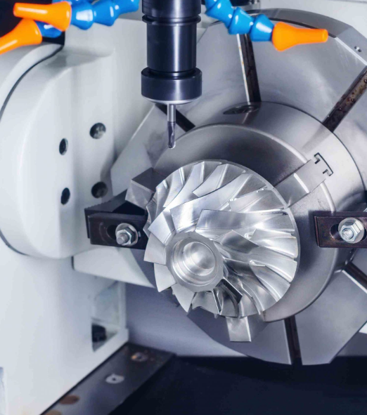
What a CNC prototype is not. It is not a substitute for production tooling, not an appearance-only mock-up, and not a 3D-printed visual. It is a real, functional, machined test article. If the test demands the production material, the prototype should match it.
Why use CNC prototyping?
CNC prototypes are most valuable when the test the prototype must pass requires real material and real mechanical behaviour. The four validation categories below are where CNC machining is usually the right choice.
Design validation
Confirm that dimensions, geometry, mating features and interfaces match the design intent before tooling is committed.
- Drawing tolerances can be checked against real parts
- As-designed geometry can be confirmed or corrected
- Interferences and assembly fit become visible
Functional validation
Run the prototype under realistic load, motion, temperature and wear to confirm mechanical behaviour.
- Strength, stiffness and fatigue behaviour
- Movement, sliding, rotation and actuation
- Heat, chemical and wear exposure where applicable
Appearance and surface validation
Confirm visible surfaces, finish, texture and proportion against brand and design intent.
- Surface finish and texture reproduction
- Colour, anodizing or plating options
- Visual proportion under real lighting
Pre-production validation
Use the prototype to de-risk the production decision — material, process, tolerance strategy and supplier.
- Validates material selection before tooling
- Confirms tolerance is achievable at production volume
- Reduces risk on the first production run
What can you test with a CNC prototype?
CNC prototypes validate a wide range of engineering questions — but not all of them. The honest picture below shows where a CNC prototype is reliable, where it is partially representative, and where it is not the right tool.
| Test | CNC prototype | What this actually means |
|---|---|---|
| Dimensional fit | Strong | Critical features can be measured against drawing tolerances and assembly mating parts. |
| Assembly verification | Strong | Snap fits, fasteners, hinges and interfaces can be tested on real material. |
| Mechanical function | Strong | Load, motion, rotation and actuation behave close to production material. |
| Thread and interface validation | Strong | Thread forms and interface features reproduce well on machined metal and plastic parts. |
| Surface finish and appearance | Partial | As-machined, brushed, polished, anodized or painted finishes can be evaluated. Cast or moulded surface characteristics are not reproduced. |
| Material behaviour | Process dependent | Mechanical properties match the chosen stock material, but machined grain direction, weld lines and porosity differ from cast or moulded parts. |
| Mass-production process replication | Not | Injection molding, die casting and similar processes produce different surface, density and grain patterns. Use a production-representative process for that test. |
| Complex internal geometry | Limited | Internal channels and enclosed cavities that the tool cannot reach are not feasible in a single-setup CNC prototype. |
Set up the test before the prototype. "Is the part OK?" is not a test. Decide what the prototype must prove — fit, strength, wear, surface, behaviour — and only then order it. A prototype that has no defined test usually gives ambiguous results.
CNC prototype manufacturing process
Nine steps from CAD to test-ready prototype. Most are short; the longest are CAD review and process setup, which is why a clear drawing and a defined test matter before the first chip is cut.
CAD review
Drawing and CAD checked against the test objective and inspection plan.
DFM analysis
Manufacturability feedback — tolerance, datum, fixturing, feature access.
Material selection
Stock chosen to match the production material and the test requirement.
Toolpath programming
Machining strategy, tool selection, speeds and feeds defined per feature.
CNC milling / turning
Material removal on 3-axis, 4-axis, 5-axis milling or turning centres.
Deburring & finishing
Edge break, surface preparation, any agreed finishing process.
Dimensional inspection
CMM, micrometer, height gauge or optical inspection per the plan.
Prototype approval
Results reviewed against the test objective; release or iterate.
Design iteration
Feedback folded back into the design until the test is passed.
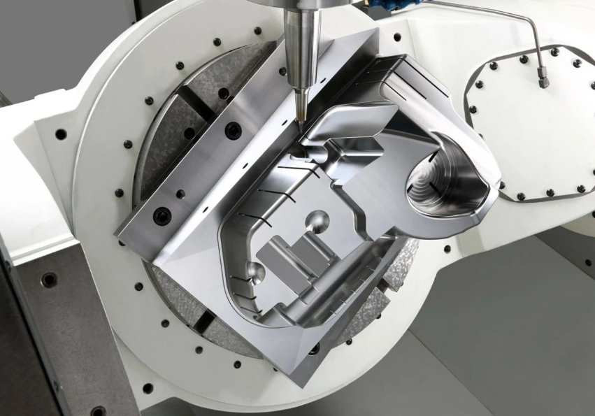
CNC prototype materials
A CNC prototype is most useful when the material matches the production material. The categories below cover what most CNC prototyping programs actually use; the exact grades, stock forms and finishes are confirmed per project — see the commercial Custom CNC Prototype Parts page for the specific list.
| Category | Typical grades | Where it is used in prototyping | Notes |
|---|---|---|---|
| Aluminum | 6061, 7075 | Housings, brackets, fixtures, structural prototypes | Most common prototyping material. Easy to machine, predictable cost and lead time. |
| Stainless steel | 303, 304, 316L | Functional prototypes, medical, industrial, corrosion-resistant parts | Slower to machine than aluminum; tooling and feeds must suit the grade. |
| Brass & copper | C360 brass, C110 copper | Electrical, thermal, fluid and decorative prototypes | Free-machining; suitable where conductivity or appearance matters. |
| Titanium | Ti-6Al-4V | Aerospace, medical, lightweight structural prototypes | Demanding machining parameters; specialist tooling usually required. |
| Engineering plastics | POM, ABS, PC, PEEK, Nylon, PTFE, HDPE | Lightweight prototypes, low-friction features, electrical insulation | Stock form, moisture and stress behaviour vary by grade. |
Material selection principle. Material choice should reflect the intended function, environment, required mechanical performance and the production material wherever practical. A CNC prototype in a weaker material may give the wrong answer to a strength test.
How accurate is CNC prototyping?
There is no single number that describes "CNC prototype accuracy". A realistic answer depends on seven factors, not on the process alone.
| Factor | Why it matters |
|---|---|
| Material | Tooling, cutting parameters and thermal behaviour vary by material — aluminum, stainless, plastics and titanium each behave differently. |
| Geometry | Thin walls, fine features and deep pockets constrain achievable tolerance; simpler shapes hold tighter bands more easily. |
| Machine capability | 3-axis, 4-axis and 5-axis machines have different envelope and precision characteristics; machine condition matters. |
| Tooling | Tool quality, runout and wear all affect achievable tolerance and surface finish. |
| Datum strategy | How the part is located and held during cutting decides whether tolerances are repeatable from part to part. |
| Tolerance specification | Over-tolerancing a drawing forces tighter process control and inspection than the function requires. |
| Inspection method | What you measure and how you measure it sets the practical ceiling on what can be claimed as "accurate". |
Practical framing for a prototype. Standard machining tolerance can usually be achieved on many features for typical prototype parts. Tighter bands — such as ±0.005 mm or below — are achievable on qualified critical features, where the feature, datum, tooling and inspection are planned together. They are not the default tolerance for an entire drawing.
For the specific capability of one supplier on one machine class, see the Custom CNC Prototype Parts page, which documents the actual machining bands available.
What determines CNC prototype cost?
CNC prototype pricing depends on what the part actually demands. The eight factors below decide the final number; fixed per-piece prices are not useful without considering all of them.
Single-piece vs small batch. A one-off prototype is usually priced differently from a small batch because programming, fixturing and setup costs are distributed across fewer parts. The per-piece cost falls as quantity rises, which is why pilot and pre-production runs are quoted separately from single prototypes.
Get a prototype-specific quote
Send your CAD file and the test the prototype must pass. You will get a project-specific quotation covering material, tolerance, inspection and finishing — not a price list.
How many prototypes should you order?
The right prototype quantity follows what you need to prove, not a fixed "1–50 pieces" range. The three stages below are typical patterns; the actual quantity is confirmed per project.
Single prototype
For first-look design and fit validation, where the question is whether the geometry works at all.
- Engineering review of the concept
- Initial fit check against mating parts
- Approval to commit to design detail
Small-batch prototypes
For assembly, functional testing and parallel engineering evaluations where multiple parts are needed at once.
- Assembly validation with mating components
- Functional and mechanical testing
- Several design alternatives evaluated in parallel
Pilot / pre-production
For pilot builds, customer samples and field testing ahead of full production release.
- Customer and field evaluation builds
- Pilot runs to validate the production process
- Pre-production samples for regulatory submission
Choose by purpose, not by category. If the question is "does it fit?", one or two parts are usually enough. If the question is "does it survive under load across the population?", pilot-batch volume with measured results is the responsible answer. The minimum order quantity for a single CNC prototype is 1 piece.
CNC prototyping vs 3D printing
The two methods answer different questions. CNC machining is generally strong on production material and mechanical testing; 3D printing is generally strong on complex geometry and fast iteration. The right choice depends on what the prototype must prove.
| Factor | CNC prototyping | 3D printing |
|---|---|---|
| Production-grade metal materials | Excellent | Process dependent — metal AM exists, with different cost, lead time and properties |
| Production-grade plastics | Excellent for engineering plastics | Process dependent — SLS, MJF and FDM each differ in properties |
| Dimensional accuracy | Tight on qualified features | Process dependent — varies from moderate to high |
| Complex internal geometry | Limited by tool reach | Excellent for enclosed channels and lattice features |
| Functional metal testing | Excellent — same material family as production | Available with metal AM, with different cost and process profile |
| Prototype speed | Fast for many parts | Very fast for many geometries, no tooling |
| Surface finish | Excellent as-machined; further finishes optional | Process dependent — layered texture, post-processing usually required |
| Tooling required | No production tooling | No tooling |
| Best for | Functional and precision prototypes, production-material testing | Complex geometry, fast concept iteration, lightweight visual models |
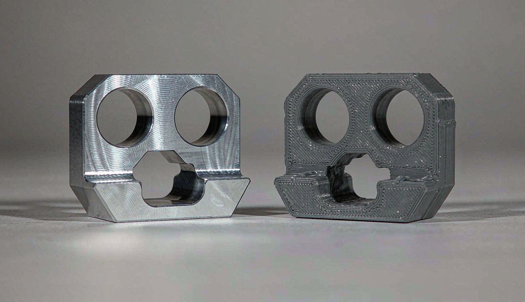
Choose based on what the prototype must prove. Geometry, material, tolerance, functional requirements, quantity and surface requirements decide the route — not a general preference for one method. If the test requires the production material, CNC is usually the right answer. If the test requires a complex internal geometry that machining cannot reach, 3D printing is usually the right answer.
CNC prototyping vs injection molding
Many programs use both — CNC prototyping to validate geometry and material behaviour early, injection molding for high-volume production. The comparison below shows where each method earns its place.
| Factor | CNC prototyping | Prototype injection mold |
|---|---|---|
| Tooling | None | Required — prototype / bridge or production tool |
| Initial cost | Lower | Higher — mold build is a capital item |
| Design changes | Easy to iterate | Expensive after tooling is cut |
| Metal prototypes | Excellent — full range of metals | Not applicable |
| Production-material simulation | Good when the same material is used | Excellent — same resin, same process, same part behaviour |
| Complex plastic geometry | Good, subject to tool access | Excellent — moulded detail and consistency |
| Low quantity (1–100 pcs) | Excellent | Usually less economical |
| High quantity (1000+ pcs) | Cost per part stays high | Economical — tooling cost distributed over volume |
| Best for | Early-stage prototypes, metal parts, design validation | Stable design, high-volume plastic parts, production-representative testing |
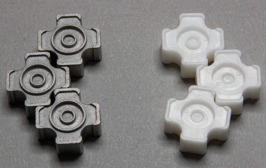
When the production path becomes moulding. Once the design is frozen and volume justifies the tooling, the next step is a prototype or bridge tool rather than continuing CNC machining. CNC prototyping is not a substitute for moulding at volume — it is the stage that makes the moulding decision safe.
From CNC prototype to production
CNC prototyping is the engineering stage, not the end of the manufacturing process. Once validation is complete, the right production route is selected based on volume, geometry, material and cost.
Concept
Design intent, requirements, target material and tolerance.
CNC prototype
Functional part in production material for fit, function and design review.
Engineering validation
Testing, iteration and sign-off against the original test objectives.
Design freeze
Material, tolerance and process locked; engineering change control begins.
Pilot batch
First production-representative build to confirm the chosen production route.
Production
Selected process at scale — CNC, injection molding, die casting or sheet metal.
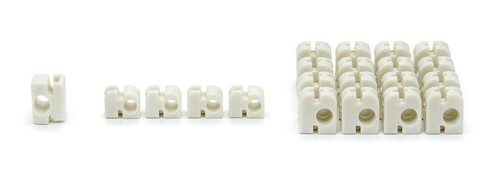
One supplier across stages. The CNC prototype partner should be able to talk to the production decision. Once the design is frozen, the supplier who machined the prototype already understands the part, the material, the tolerance and the inspection data — that knowledge is what makes the production stage safer.
How to choose a CNC prototype supplier
Eight checks that separate a real prototype supplier from a job shop. Each of these should be answerable with evidence, not just a marketing claim.
Compare a real supplier against this list
The companion commercial page documents each of these eight points with actual capability data — see how Goldcattle matches the criteria.
Technical information on this page is provided for general manufacturing guidance. Actual tolerances, material availability, lead times and production recommendations should be confirmed against the project drawing and manufacturing requirements. Figures cited for production capability (tolerance, surface finish, lead time, material list) reflect actual capability at the supplier's facility at the time of writing and are reviewed per project.
Frequently asked questions about CNC prototyping
What is a CNC prototype?
A CNC prototype is a functional part produced by computer-controlled machining directly from a digital CAD design. Unlike appearance-only models, CNC prototypes are made from production-grade metals or engineering plastics and can be used to validate fit, form and mechanical function before tooling or volume production.
When should I use a CNC prototype instead of 3D printing?
Choose CNC when the test requires the production material, tight tolerance, mechanical function or assembly fit on a machined surface. Choose 3D printing when the test requires complex internal geometry that machining cannot reach, when speed of iteration matters more than material authenticity, or for appearance models where material behaviour is not the question.
How accurate can a CNC prototype be?
CNC prototype accuracy depends on material, geometry, machine capability, tooling, datum strategy, tolerance specification and inspection method, not on a single number. Standard machining tolerances can be achieved for many features, while tighter bands typically require dedicated process planning and inspection.
Can a single CNC prototype be made?
Yes. Single-piece CNC prototypes are a standard request for early design and fit validation. Setup and programming cost is distributed across that single part, which is why unit cost is higher than at small-batch volumes. Quote, lead time and inspection scope are agreed per project.
What materials can be CNC prototyped?
The most common categories are aluminum (6061, 7075), stainless steel (303, 304, 316L), brass and copper, titanium (Ti-6Al-4V), and engineering plastics such as POM, ABS, PC, PEEK, Nylon, PTFE and HDPE. Stock grade and form are confirmed against the production material and the test the prototype must pass.
How long does a CNC prototype take?
Lead time depends on material, geometry, tolerance, finishing and inspection scope, not just on cutting time. A simple aluminum prototype may quote in days; a complex 5-axis part with tight tolerance, finishing and inspection typically quotes in a longer planning window. The supplier should give a project-specific range rather than a fixed number.
How is CNC prototype cost calculated?
Eight drivers decide cost: material, part size, machining time, complexity, tolerance, quantity, surface finish and inspection requirements. A one-off prototype is priced differently from a small batch because programming, fixturing and setup are distributed across fewer parts.
Should my CNC prototype use the production material?
Usually yes, when the test must prove strength, heat, friction, wear, assembly or dimensional behaviour. For early shape and concept checks where material behaviour is not the question, a suitable substitute may be enough. The prototype material should follow the test objective.
Can CNC prototypes be anodized, plated or painted?
Yes, where compatible with the chosen material and process. Common finishes are anodizing, sandblasting, brushing, polishing, plating, painting and passivation. Specify finishing in the RFQ where it is part of the validation plan.
How many CNC prototypes should I order?
One or two for first-look fit checks; a small batch of three to ten for assembly and functional testing; a pilot batch of ten to one hundred or more for customer evaluation and field testing. The right quantity follows what the prototype must prove, not a fixed range.
When should I move from CNC prototype to production?
Move from CNC prototype to production once the design is frozen, the material is locked and the tolerance strategy is stable. The next production process is then chosen based on volume, geometry, material and cost targets — for example injection molding for high-volume plastics, die casting for metals, or continued CNC machining for low-volume precision parts.
Can the same supplier do CNC prototyping and injection molding?
Yes, many OEM/ODM manufacturers run both in-house. The advantage is continuity: the prototype partner already understands the material, the tolerance and the inspection data, so the production-stage decision starts with knowledge rather than a clean sheet.
What CAD files does a CNC prototype supplier need?
A 3D model — STEP, STP, IGES, IGS, SAT or X_T — and where applicable a 2D drawing with critical dimensions, tolerances, surface finish and material specification. A complete package shortens review and quote time.
Turn your CAD into a test-ready CNC prototype
This guide explains the technology. The commercial page handles capability, machine types, material list, tolerance bands and project-specific quoting. Send your CAD file and tell us what the prototype must prove.
Accepted files: STEP / STP · IGES / IGS · SAT · X_T · DWG · PDFContinue with the CNC topic cluster
This guide handles the "what and why" of CNC prototyping. The pages below handle the "how much", "how accurate", "how fast" and "how to source" — all part of the same cluster.