Custom Stamped Automotive Bumper Brackets & Mounting Components
Custom stamped metal components for automotive bumper assemblies, developed to approved drawings and project specifications. Share your part geometry, material requirements, production volume and inspection criteria for a manufacturing feasibility review.
This page covers the mounting side of a bumper assembly — brackets, support plates, connection plates and mounting components. Crash-relevant structures such as the reinforcement beam, the energy absorber and the crash boxes are a different component family with their own design and validation requirements; the boundary is set out explicitly below so you can tell which side your part falls on before you send an enquiry.
At a Glance
Scope and Boundaries: Which Bumper Component Are You Buying?
Short answer: a bumper assembly is a stack of parts that do not share the same engineering obligations. Brackets and support plates are dimensional and corrosion-critical; the reinforcement beam, the energy absorber and the crash boxes are crash-relevant structures. They are different products, and they are not interchangeable as a purchasing subject.
| Component | Primary obligation | What that means for sourcing |
|---|---|---|
| Mounting brackets, support plates, connection plates, mounting components | Dimensional accuracy of the interfaces, formed-feature control, corrosion protection, batch consistency | Quoted from your drawing. This is the scope of this page, and it is where a stamping supplier is evaluated on tooling, gauges and documentation. |
| Reinforcement beam, energy absorber, crash boxes | Structural performance in a defined impact case, validated as part of the vehicle system | Not claimed here. These involve high-strength or advanced steel grades, forming routes such as roll forming or other dedicated processes, joining, and structural validation that belongs to the vehicle programme. |
- A stamped bracket and a stamped beam are not the same product with a different drawing. One is bought on dimensional and corrosion performance; the other is bought on validated structural behaviour, and its design and material selection are normally fixed by the customer or the vehicle programme.
- Stating the scope protects the programme as much as the supplier. A crash-relevant part placed on a general stamping quotation will be priced against the wrong assumptions, and the gap shows up later, usually as an unplanned validation requirement.
- If your part is a crash-relevant structure, say so in the enquiry. It will be reviewed as a separate project with its own requirements, material route and validation plan rather than treated as an extension of bracket work.
Which Bumper Stamping Components Can Be Customized?
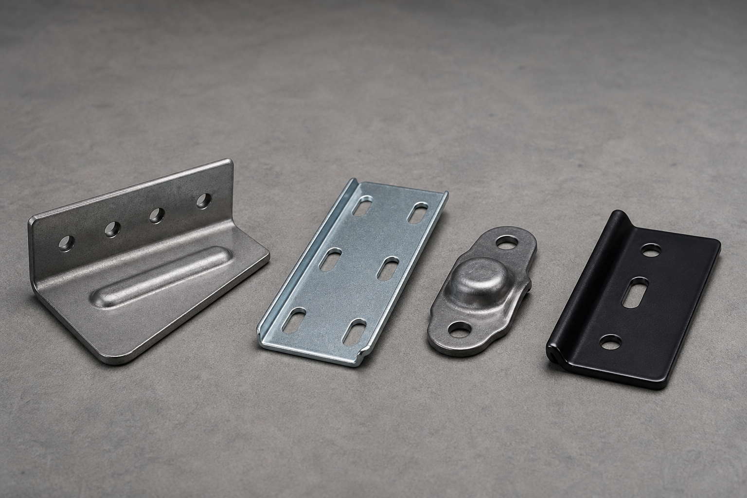
Short answer: the components on the mounting side of the assembly, made to your drawing. Each family below exists because a particular set of features drives its tooling and its inspection.
Bumper mounting brackets
Bolt the bumper assembly to the body structure. The mounting hole pattern, the bend angles and the flatness of the fixing flange decide whether it assembles without preload.
Bumper support plates
Spread the fixing load and stiffen the fixing area. Thickness, pressed rib form and hole position relative to the datum are the usual controls.
Connection and joining plates
Join the mounting structure to adjacent components. Slots and formed edges usually carry the assembly adjustment, so their position and size are the critical features.
Formed reinforcement brackets
Local stiffening of a bracket or a panel area — not a crash structure. Pressed ribs, beads and drawn bosses are the forming features that create the stiffness.
Mounting and fixing components
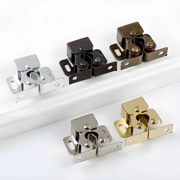
Small stamped retainers, spacers, clip brackets and trim fixings. Small parts, but often the ones where hole position tolerance matters most.
Sensor and trim brackets
Mount sensors, cameras and trim on the front end. Position stability relative to a datum matters more than load, and the coating must not disturb the interface.
Part Specifications and Customization Options
Short answer: ten parameters define a stamped bumper component. Answering them per part number is what turns an enquiry into a quotation instead of a thread of clarifying emails.
| Parameter | What the buyer should specify |
|---|---|
| Part type | Bracket, support plate, connection plate, reinforcement bracket or another stamped mounting component |
| Drawing and revision | 2D drawing and/or 3D model, with the current released revision identified |
| Material | The exact grade and the applicable material specification — not a material family |
| Material thickness | Nominal thickness and the permitted variation, and whether the strip condition is specified (bare, coated, finish) |
| Critical dimensions | Mounting holes, interface points, bend angles, formed features and the profile dimensions that matter |
| Surface requirements | Coating type, corrosion criterion, appearance requirement, and whether the coating may cover the interface |
| Tooling | New tooling, existing tooling to be used, or a transfer-tooling review of a tool you already own |
| Production volume | Prototype quantity, initial order quantity and estimated annual demand |
| Quality documents | Material certificates, dimensional reports, first-article documentation or customer-specific documents |
| Delivery | Sample approval date, production ramp-up, packaging and shipment requirement |
This list is repeated as a working checklist in preparing an RFQ at the end of the page, so it can be forwarded to an engineering or purchasing colleague as it stands.
DFM Review Before Tooling
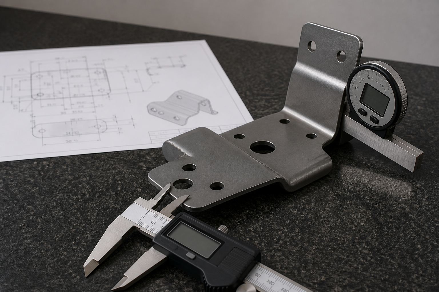
Short answer: the review exists to find the forming and interface problems while they are still lines on a drawing. Once the tool is cut, the same problem costs a tool modification instead of an email.
| What the review examines | Why it matters on a bumper component | Typical outcome |
|---|---|---|
| Material and thickness against the formed features | A feature that forms cleanly in one grade or thickness may crack, thin out or wrinkle in another | A confirmed material and thickness, or a stated limit on what the drawing can be formed from |
| Bend radii against material and thickness | A radius that is too tight for the material produces cracking or an inconsistent angle after springback | Radii confirmed or adjusted on the drawing before tooling |
| Hole position relative to bends and edges | Holes placed too close to a bend distort when the material stretches, and the mounting pattern then misses | Hole positions shifted or the forming sequence adjusted |
| Pierced holes versus the hole specification | Hole size, position and burr side (which face the burr lands on) are decisions, not defaults | Punch direction and hole specification agreed, burr side stated |
| Formability risk and springback | Formed features that spring back change the effective angle after the tool opens | Feature geometry or the forming route adjusted; compensation allowed for in the tool |
| Interface and datum scheme | The mounting pattern has to be controlled against a defined datum, and that datum has to be reachable in the tool and in the gauge | A datum scheme that survives from the drawing to the tool to the check fixture |
| Coating against the interface | Coating thickness on a mating face or inside a hole changes the fit and can prevent assembly | Masking, an allowance, or confirmation that the interface is coated by design |
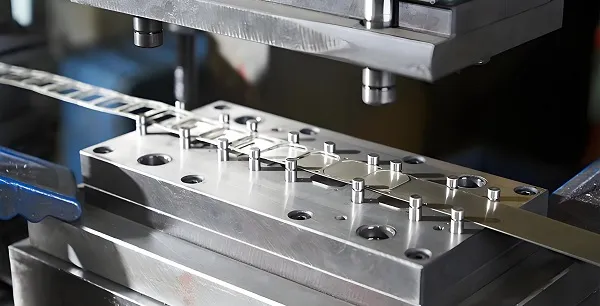
| Tooling consequence | One extra forming feature can add a station, an operation or a second tool | The tooling concept and its investment stated with the quotation |
Tooling Strategy for Bumper Components
Short answer: the tooling decision follows the part count, the forming complexity and the volume the programme can justify — not the part name.
| Situation | Route to evaluate | What drives the decision |
|---|---|---|
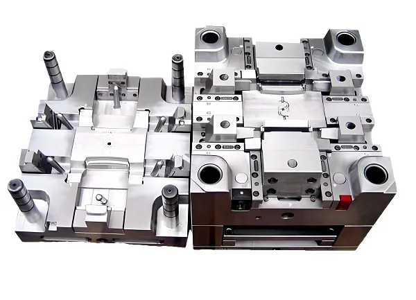
| A bracket needing several forming operations plus a controlled hole pattern | Multi-station tooling | The number of operations and the interface control justify the investment once volume is committed |
| A simple bracket or support plate in low volume | Single-operation tooling or a simpler arrangement | Keeping tooling investment low matters more than the per-piece cost at this volume |
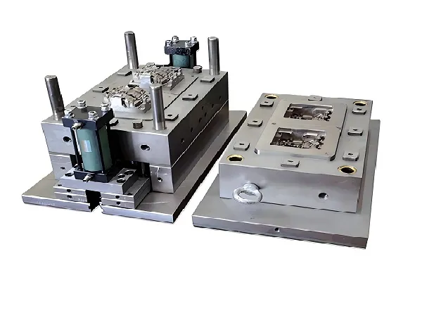
| Prototype and sample parts before series tooling | A prototype route or temporary tooling | Proving form, fit and function before the tooling commitment is made |
| A tool you already own, or one to be transferred | A transfer review of the existing tool | Tool condition, revision level, and whether the interface can still be held — established before it is loaded |
| A very high volume of simple geometry | Compare the forming routes before committing | At volume the route economics change, and the answer is not automatically the same process |
Tooling ownership and maintenance are commercial terms, not technical ones. Who owns the tool when you pay for it, who stores and maintains it, what constitutes normal wear, and what happens if the part is moved or the programme ends — all of that belongs in the quotation and the agreement, and should be settled before the tool is cut rather than after.
Process Selection: When Stamping Is the Right Route
Short answer: stamping earns its tooling when a part is repeated and its geometry suits forming. For a one-off or a very low volume of simple geometry, a cutting or fabrication route can be the better answer — and saying so early is cheaper than discovering it after tooling.
| Situation | Route to evaluate | Why |
|---|---|---|
| Repeated parts with formed features and a committed volume | Stamping | Tooling is amortised across the volume, and forming gives consistent geometry part after part |
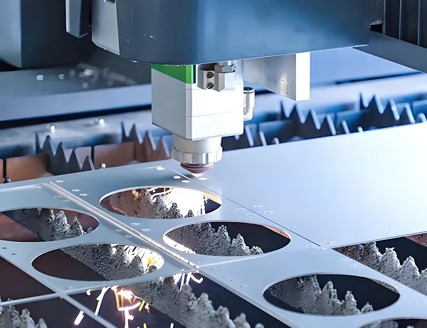
| Very low volume, large or simple geometry | Cutting (laser or waterjet) with forming or fabrication | Tooling investment is not justified, and a cut-and-form route proves the design sooner |
| A few thick, stiff parts where surface finish is secondary | Machining from plate or a fabricated assembly | No tooling commitment, and thickness is not limited by strip availability |
| Long uniform sections in quantity | A different family of processes entirely | Formed strip is the wrong starting point for a profile that is constant along its length |
Materials and Thickness Selection
Short answer: the grade and the material specification come from your drawing. What we contribute is a judgement on whether the specified material can be formed into the specified geometry at the specified thickness — and that judgement is made in the DFM review, not by publishing a table of numbers.
| Material direction | Where it typically suits a bumper component | What has to be named with it |
|---|---|---|
| Cold-rolled low-carbon steel sheet | General brackets, support plates and components that need a consistent surface for a subsequent coating | Grade, the applicable material specification, thickness and permitted thickness variation |
| Hot-rolled steel | Thicker support components where the surface finish is not critical | Grade and specification, thickness, and the surface condition — it affects coating adhesion |
| Coated strip (zinc-coated or similar) | Parts where the strip itself carries the corrosion protection, or parts prepared for painting | The coating type and designation, and how the coating behaves at bends and cut edges |
| Stainless steel sheet | Corrosion-exposed brackets where the material, not a coating, provides the protection | Grade family, surface finish and the material specification |
| Aluminium sheet | Weight-driven brackets, with a different corrosion and joining logic | Alloy and temper, the material specification, and the joining method used in the assembly |
| High-strength and advanced steel grades | Only where the programme defines them, usually on crash-relevant structures | Grade, specification, forming route and the validation the programme requires — a project-specific decision, not a default |
The page previously carried three lines giving a tensile strength, a yield strength and a thickness range for cold-rolled steel, hot-rolled steel and stainless steel. Those numbers are not engineering information, because none of them was tied to a grade, a material specification, a condition of supply or a section. A tensile figure without a grade is not a property of anything in particular, and a thickness range that claims to cover every bumper stamping is describing a stock list rather than a part.
Where those numbers are needed, they come from the material specification named on your drawing, at the thickness the part actually uses. Published property data for the grades we hold is on the materials page, and the forming judgement for your geometry is made part by part in the DFM review.
Corrosion Protection and Surface Treatment
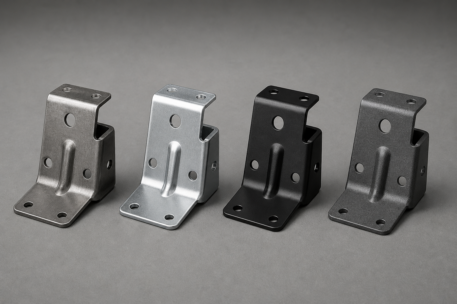
Short answer: on a bumper component the coating is a specification with acceptance criteria, not a finish preference — and it changes the fit wherever it lands on a mating face or inside a hole.
| Protection direction | Typically used where | What has to be specified and verified |
|---|---|---|
| Zinc plating (electroplated) | Brackets and smaller components needing a controlled, uniform coating | Coating designation and thickness range, coverage on cut edges and around holes, and whether threads or mating faces are to be masked |
| Pre-coated strip (zinc-coated steel) | Where the protection comes from the material itself | Coating designation, behaviour at bends (cracking risk), and how cut edges are protected |
| Electrocoat | Components that form part of an assembly painted as a unit | Coating specification, film thickness, adhesion, and coverage inside formed features |
| Powder coating | Exposed or visible brackets | Finish and colour, film thickness, adhesion, and whether the film thickness interferes with the interface |
| Material-based protection | Stainless or aluminium parts where the material carries the corrosion performance | The grade and surface finish, and the fact that this is a material decision rather than a coating one |
Where the coating is applied by a specialist process, the coating record comes from that process and is identified as such. It is normal for the part supplier and the coater to be different parties; what matters is that the specification, the acceptance criteria and the traceability between the two are defined.
Material, Corrosion and Compliance Requirements
Short answer: the part supplier controls the material and coating it supplies and can document them. The compliance of the vehicle — and any regulatory scope question — belongs to the programme that places it on the market.
| Requirement | What it applies to | What the part supplier can provide | What it cannot decide |
|---|---|---|---|
| Restricted substances in vehicles and their components | Vehicles and components placed on the market, where materials such as lead, mercury, cadmium or hexavalent chromium are restricted | Declarations covering the material and the coating chemistry of the parts supplied, to the extent the applicable rules require them | The vehicle-level assessment, the applicability of any exemption, and the scope question — all of which depend on the material, the application and the version of the rules in force |
| Material and substance data for the supplied parts | Programmes that require substance reporting up the supply chain | Composition data for the steel or aluminium and for the coating chemistry, with the mass basis where it is required | Who files a declaration and in what system — that follows from where you sit in the chain, not from us |
| Recyclability information | Where end-of-life requirements ask for material information | Material composition by mass for the parts we supply | The vehicle-level recyclability calculation, which depends on the whole vehicle |
| Vehicle safety and type approval | The vehicle and its systems, including front-end and bumper structures | Conformance of the part to the drawing and requirements you specify, with the inspection record | Any statement that a vehicle or assembly meets a safety regulation. That responsibility sits with the manufacturer of the vehicle or the system. |
| Your own material specification | Whatever your programme calls for | The material purchased to that specification and certified to it | A specification we were not given. The requirement has to be named in the enquiry. |
Compliance cannot be inferred from a material name. A cold-rolled steel bracket with a zinc coating and the same bracket with a different coating are not automatically equivalent in substance terms, and a material that satisfies one programme requirement may not satisfy another.
What we do is straightforward: the material and coating are purchased and recorded against the specification you name, and the declarations your programme requires are scoped with the quotation. What we do not do is certify a vehicle, decide a regulatory scope on your behalf, or state that a stamped component meets a safety requirement that is validated at vehicle level. Say which documents you need and they are quoted with the part.
Our own environmental and responsibility information is published separately on the sustainability and responsibility page.
Dimensional Inspection and Production Quality
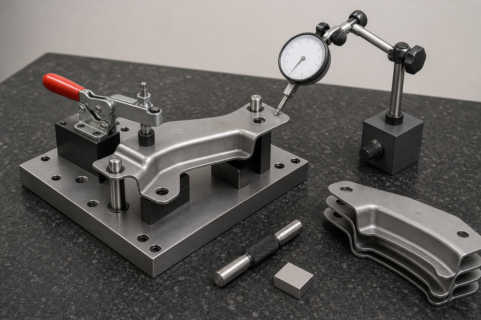
Short answer: on a mounting component, the inspection that decides whether the part works is the mounting interface and the formed features. Everything else is confirmed against the drawing, and the scope is agreed before the order rather than after it.
| Inspection stage | What it covers | What it depends on |
|---|---|---|
| Incoming material | The strip grade, specification and batch identified against the material certificate, and the thickness where the part is sensitive to it | The material specification named on your drawing |
| First-off and first-article check | The formed features and the critical characteristics measured at the start of the run against the drawing | The characteristics listed for the part, agreed at quotation |
| Interface check | The mounting hole pattern verified with a fixture or gauges so it is controlled as a pattern | A datum scheme that is the same one the tool was built to |
| In-process checks | The characteristics that move during a run: bend angles, the height of formed features, hole condition and burr side | The check frequency agreed for the part and the volume |
| Final check | The listed critical characteristics and, for visible parts, the appearance against an agreed standard | The report scope and the appearance standard agreed at quotation |
| Coating verification | That the specified coating was applied, with the thickness or appearance criteria the programme requires | The coating specification, and whether verification is part of the order |
| Packing | Protection against handling damage between the last inspection and your receiving area | The packaging method agreed for the part and the destination |
Quality Documents for an Automotive Programme
Short answer: the automotive document set is defined by your programme, not by the supplier’s marketing. What matters is which document covers which characteristics, and that the scope is agreed at quotation.
| Document | What it demonstrates | What it does not demonstrate |
|---|---|---|
| Material certificate | The grade, specification and batch of the strip that was purchased | That a particular part was made from that batch, unless batch records link the two |
| Dimensional inspection record | Measured values against the drawing for the characteristics listed on it | Anything outside the listed characteristics, or the sampling basis unless that is stated |
| First-article documentation | Every listed characteristic documented for a first article at the start of the programme | Later production, unless the process is held and monitored afterwards |
| Interface or fixture check record | That the mounting pattern was verified as a pattern | The complete dimensional conformance of the part — it verifies what the fixture checks |
| Coating record | The coating specification that was applied, from the process that applied it | The part dimensions, unless measurement after coating is part of the scope |
| Certificate of conformity | A declaration that the order conforms to the agreed specification | It is an assertion of conformity, not a measurement |
| Programme-specific submission documents | Whatever your programme requires, at the level it requires | Anything that was not requested — the set and the level are set by the customer |
What Each Procurement Stage Needs
Short answer: a stamped component is bought across six stages, and each one asks a different question. Answering them in order is what keeps a programme from discovering a requirement after the tool is cut.
| Stage | What you need to know | What we provide |
|---|---|---|
| Engineering enquiry | Can the drawing be made, and is the design sound for forming? | Accepted drawing and model formats, the DFM review, the critical features identified and a feasibility position |
| Tooling decision | Is the tooling investment justified, and what happens later if the part changes? | The tooling concept and its investment, the ownership and maintenance terms, and the consequences of a later change |
| Sample stage | Does the sample satisfy the assembly and the interface? | Sample parts, the dimensional record for the agreed characteristics, and the basis on which the sample is approved |
| Supplier approval | Does the supplier meet the purchasing and quality requirements? | The documents and declarations the programme requires, agreed and scoped rather than assumed |
| Production | Is batch-to-batch consistency held? | Critical characteristic checks, batch traceability, change control and a defined route for nonconforming parts |
| Logistics and delivery | Do the parts arrive intact and identifiable? | Packaging, labelling, corrosion protection for the journey, and delivery planning with you |
What Affects the Cost of a Stamped Bumper Component
Short answer: the tooling investment and the material utilisation usually explain more of a stamped part’s cost than the forming operation itself. Comparing per-piece prices without comparing those two is not a comparison.
| Cost factor | Why it moves the quotation |
|---|---|
| Material and thickness | Decides the material cost, and also the forming difficulty and the press or tooling requirement |
| Part geometry | Complex bends, drawn features, formed ribs and critical hole patterns increase tooling complexity and the number of operations |
| Tooling type | Single-operation, compound and multi-station tooling have different initial investments and different suitable volumes |
| Order quantity | Sets how the tooling investment is amortised, how often the tool is changed, and the per-piece cost |
| Tolerance and inspection | Drives the gauges, fixtures, inspection frequency and process control needed to hold the critical characteristics |
| Surface treatment and secondary operations | Adds processes, external coordination and handling between operations, which also affects lead time |
| Packaging and logistics | Affects part protection, packing method, freight cost and the delivery arrangement |
How to Prepare an RFQ for Custom Bumper Stampings
Short answer: send the ten parameters in one package and the quotation can state its assumptions instead of asking for them. Each item below becomes a line in the review.
- Part type: bracket, support plate, connection plate or another mounting component
- 2D drawing and/or 3D model, with the current released revision identified
- Material: exact grade and the applicable material specification
- Nominal thickness, permitted variation, and the strip condition if it is specified
- Critical dimensions: mounting holes, interfaces, bend angles and formed features
- Surface requirement: coating type, corrosion criterion and whether the interface may be coated
- Tooling: new tooling, existing tooling, or a transfer review of a tool you own
- Volumes: prototype quantity, initial order quantity and estimated annual demand
- Quality documents required, and the submission level if your programme defines one
- Delivery: sample approval date, production ramp-up and shipment requirement
How the quotation is assembled. Tooling, sample parts, sample approval and series production are quoted as separate stages, because each depends on the one before it. Asking for a single number covering all four tends to produce an answer that has to be revised once the tooling is proved, which is worse for planning than four figures you can schedule against.
FAQ
Can you manufacture custom automotive bumper brackets from drawings?
Yes — stamped brackets, support plates and mounting components are quoted from a 2D drawing, a 3D model or an approved sample, with the current revision identified. The feasibility review covers the specified material and thickness, the formed features, the critical interfaces and the inspection requirement, and the quotation states the assumptions it was built on rather than leaving them implicit.
Which materials and thicknesses can be stamped?
The material is taken from the drawing or the material specification your programme names, because mechanical properties depend on the grade, the applicable material standard, the condition of supply and the thickness. Where a programme has not yet fixed the grade, the DFM review proposes candidates and states what still has to be confirmed. A property table covering cold-rolled, hot-rolled and stainless steel is not a substitute for the standard your drawing calls for.
How do you determine the right stamping process?
The process follows the part geometry, the annual volume and the tooling investment the programme can justify. The number of forming operations, the interface control and the total part count usually decide between a simple tool and a more complex arrangement. The comparison of progressive, transfer and fine-blanking routes is published on the custom metal stamping parts page rather than repeated here.
How are hole positions and mounting interfaces inspected?
The mounting interface is verified against the drawing by the method agreed for that feature: locating pins in a dedicated check fixture for the pattern as a whole, gauges for hole size, and dimensional report values for the critical characteristics listed for the part. Which characteristics appear on the record, and how often they are checked, is agreed with the quotation rather than assumed afterwards.
Can you supply PPAP or other automotive quality documents?
Automotive documentation is agreed against the requirements of the individual programme, because the document set and the submission level are set by the customer rather than by the supplier. Name the documents and the level in the enquiry so they can be scoped with the quotation. The management system certification status and the current certificate list are on the quality certifications page.
Can you manufacture bumper reinforcement beams or crash boxes?
Those are a different component family from the mounting brackets and support plates covered by this page. Reinforcement beams, crash boxes and energy absorbers are crash-relevant structures: their design, material selection and validation requirements are set by the vehicle programme, and they commonly involve high-strength or advanced steel grades, dedicated forming routes and structural validation. They are reviewed as a separate project with their own requirements, not treated as an extension of bracket work.
How is tooling and production lead time estimated?
Tooling, sample parts, sample approval and series production are separate stages with separate durations, and they are quoted separately. A single figure covering the whole sequence hides the dependencies: sample parts cannot begin until the tool is proved, and production cannot begin until the samples are approved. If your programme needs a particular date, say which stage it applies to.
What information is needed for a quotation?
The drawing and its revision, the material grade and material specification, the nominal thickness and permitted variation, the critical dimensions and interfaces, the surface or coating requirement, the production volumes, the quality documents required and the delivery requirement. These are set out above as the RFQ checklist, and they can be forwarded as they stand.
Do you have bumper stamping case studies?
We do not publish customer names or invent project examples. Where a reference can be shared it is shared with the customer’s permission and covers the fields that can be verified: the requirement, the part and material, the process route, the key characteristics and how they were verified. The published project examples on the custom metal stamping parts page are stamped-metal projects in other applications, not bumper projects, and they are labelled as such rather than presented as bumper work.
Related Pages and How This Page Fits
This page handles one application: bumper mounting components. The neighbouring subjects are deliberately kept on their own pages so that two pages do not end up publishing different versions of the same figures.
| Page | What it covers |
|---|---|
| Custom metal stamping parts | The general stamping capability: material selection, the process comparison, published tolerances, thickness capability, the staged workflow timings and the quality regime |
| Metal stamping dies | Die types and their working principles, the classification of single-operation, compound and progressive dies, and their application |
| Metal stamping mold introduction | Die materials and the die development and customization sequence |
| Materials | Published property data for the grades we hold, and material selection guidance |
| Quality certifications | The management system certification status and the current certificate list |
| Sheet metal fabrication | The forming and fabrication side of the business, and the routes available when stamping is not the answer |
| Sample policy | How sample parts and sample approval are handled |
| Shipping and tariffs | Shipping terms and the import considerations that affect delivered cost |
| CNC machining services | Machined components, for the parts on a bumper assembly that are machined rather than formed |
Send the part, the material and the volume
A stamped bumper component can be quoted accurately once the drawing revision, the material specification, the thickness, the critical interfaces, the coating requirement and the volume are on the table. Send them together and the review comes back with the forming risks, the tooling position and the inspection scope rather than a number to be renegotiated.
Free drawing review · NDA available on request · Quotation states the material, tooling and inspection assumptions it is based on