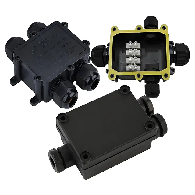

Custom IP68 Junction Box | ABS/PC/Alu/S.Steel
Standard Specifications
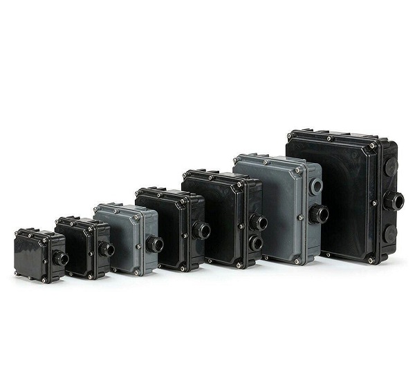
Small model: 53×55×37mm (matchbox size), suitable for sensor and instrument wiring.
Medium – large model: 400×600×185mm, supporting multi – channel cable branching and complex wiring.
Non – standard Customization
Customization of extra – large sizes with a length ≤1200mm and a width ≤800mm is supported, and the depth can be adjusted according to requirements (including rib design).
Protection Levels
Basic version: IP66 (dust – proof + strong water – jet protection), suitable for outdoor general environments.
Enhanced version: IP68 (continuous protection underwater at a depth of 30 meters), suitable for scenarios such as underground cables and ships.
Environmental Adaptability
Operating temperature: For ABS version, – 30℃ ~ +80℃; for PC version, – 50℃ ~ +120℃; for metal version, – 40℃ ~ +150℃.
Corrosion resistance: Passes the salt – spray test for ≥500 hours (metal materials), resistant to acid, alkali, and oil erosion.
Description
Custom IP68 Waterproof Electrical Junction Box
Sealed enclosures built around your cable layout, mounting and environment — quoted from your drawing, not pulled from a catalog shelf.
- IP68validated to your immersion condition
- ≤1200×800 mmcustom size on drawing
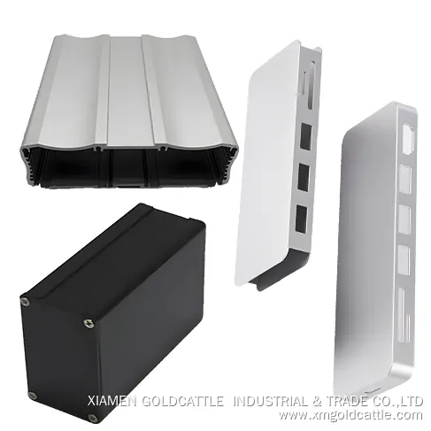
- ABS / PC / Alu / SShousing matched to use
- DIN · PCB · terminalinternal mounting ready
Product Snapshot
A custom IP68 junction box is a sealed electrical enclosure specified from your application — not a stock part with options bolted on. The table below captures what we set per order.
| Product type | Custom sealed electrical junction enclosure |
|---|---|
| Ingress protection | IP66 standard; IP68 per the immersion condition stated in your order |
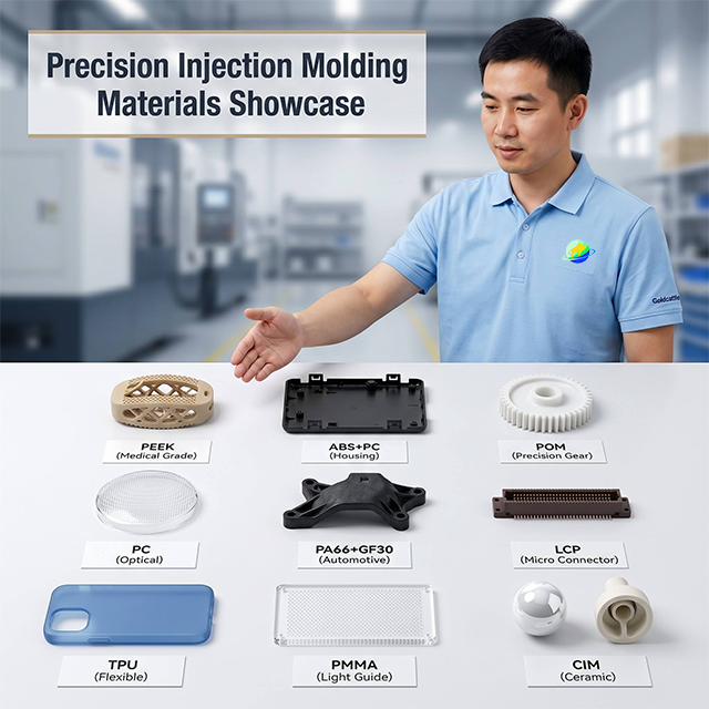
| Housing | ABS / polycarbonate / aluminum / stainless steel |
| Standard sizes | 53 × 55 × 37 mm up to 400 × 600 × 185 mm |
| Custom size | Up to 1200 × 800 mm (length × width) |
| Cable entry | 2–6 glands, cable Ø 6–32 mm, user-defined positions |
| Sealing | Silicone gasket + compression-sealed cable glands |
| Mounting | Wall / pole / DIN rail / internal bosses |
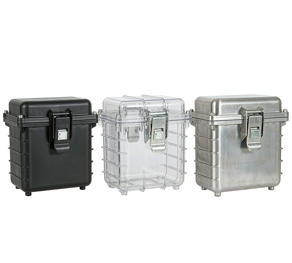
| Cover | Solid or transparent polycarbonate |
| Customization | Dimensions, holes, inserts, glands, labeling, internal layout |
IP68 is defined by the manufacturer-declared immersion condition (depth and duration) under IEC 60529. We validate the rating against the condition written into your order, not a single universal depth.
Size Range and Model Codes
Three build tiers cover most projects. Part numbers follow Goldcattle's GC-IP68 sizing convention; custom dimensions replace the size code with your drawing reference.
- Compact — GC-IP68-053, ~53 × 55 × 37 mm. Sensors, LED drivers, small PCBs.
- Large — GC-IP68-400, up to 400 × 600 × 185 mm. Combiner boxes, control terminations.
- Custom — GC-IP68-CUST, ≤1200 × 800 mm. Drawn to your envelope and wall pack.
How an IP68 Box Is Built — Cutaway
Sealing is a system, not a single gasket. Eight elements work together to keep water out under immersion.
Why Buyers Specify a Custom IP68 Box
Sealed for continuous immersion
IP68 is validated to the depth and time your application actually sees — underground pits, marine bilges, flooded cabinets.
Cable entries where the harness needs them
Gland count, diameter, thread and position are set from your drawing, so field wiring is clean and the seal stays intact.
Housing matched to the environment
ABS for cost, PC for heat and clarity, aluminum for rigidity, stainless for corrosion — no over-spec or under-spec.
Internal mounting ready
DIN rail, PCB standoffs and terminal blocks are built in, so assembly stops being a drilling job on site.
One supplier, one quality system
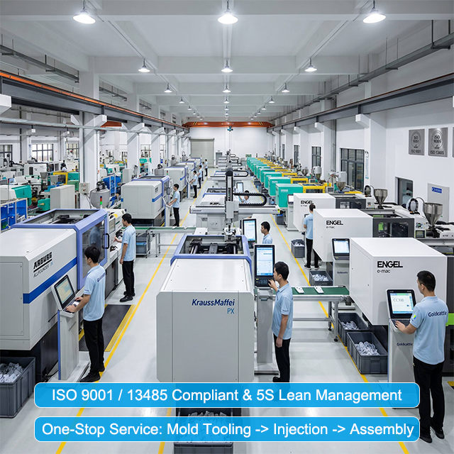
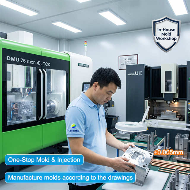
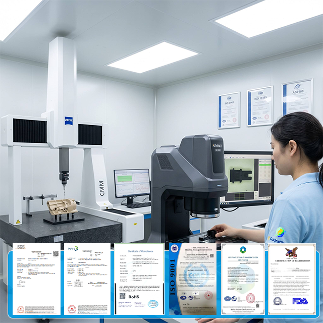
Tooling, molding or casting, machining, gland fit and test sit under one ISO 9001:2015 system — one drawing in, one accountable build.
IP66 vs IP68 — What the Rating Actually Means
Both are defined by IEC 60529. The second digit is what matters for water.
IP66
Protected against powerful water jets from any direction. Right for most outdoor wall-mounted runs, machine backsplashes and weather-exposed terminations that will not sit underwater.
IP68
Protected against continuous immersion. The depth and duration are declared by the manufacturer for the product — there is no single "IP68 = 30 m" rule. A tested configuration such as 1 m for 24 h (a condition some enclosure makers publish as their declared rating) is an example of how a maker states the condition, not a universal definition. We validate to the condition in your order.
Rule of thumb: if the box may be submerged or sit in standing water, specify IP68 with the immersion depth and time. If it only faces rain and spray, IP66 is usually enough and cheaper to build.
Housing Material Options
| ABS | Cost-effective indoor and light-outdoor use. Specific ABS grades can achieve UL94 V-0 — confirm the exact grade and rating on your material specification. |
|---|---|
| Polycarbonate (PC) | Higher temperature and impact resistance, transparent cover option. Glass-filled PC grades can reach 5VA; the rating depends on the exact grade and wall section. |
| Aluminum (die-cast) | EMI shielding, rigid, −40 to +150 °C service range. Good for EMI-sensitive and mechanically loaded enclosures. |
| Stainless steel (304/316) | Marine and corrosive duty. Finished for corrosion resistance and can be salt-spray tested per ASTM B117 / ISO 9227 on request. |
Configure the Junction Box Around Your Application
Seven steps take a drawing to a quotable build. Send us the output of step 7 and we return a quote plus a feasibility review.
- 1
Define the environment
Indoor, outdoor, underground pit, marine deck or factory floor sets the material and rating.
- 2
Choose the housing
ABS, PC, aluminum or stainless steel matched to temperature, impact and corrosion.
- 3
Set dimensions and wall
Length, width, height and wall thickness driven by size, load and process.
- 4
Place the cable glands
Count, cable diameter, thread (metric or PG), side and orientation from your harness.
- 5
Specify internal mounting
DIN rail, PCB standoffs, terminal blocks or mini breakers.
- 6
Add holes, inserts, labels
Threaded inserts, mounting brackets, laser labels and color.
- 7
Send the drawing
STEP or PDF plus quantity — we quote and validate the IP condition.
Customized Internal Mounting Layout
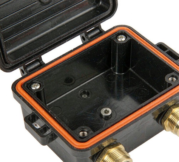
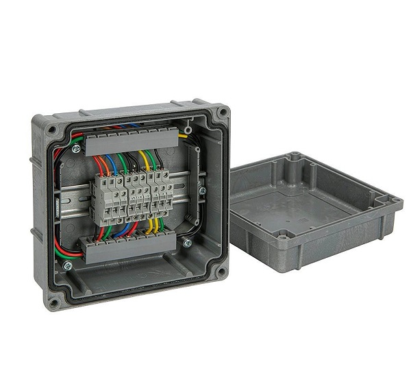
Internal layout is built to your schematic, not added later:
- DIN rail (35 mm) for breakers and relays
- PCB standoffs and routed cable channels
- Terminal blocks and busbars
- Molded mounting bosses and threaded inserts
- Cable clamps and strain relief
What Makes a Junction Box IP68?
An IP68 rating is the sum of eight conditions. Miss one and immersion fails.
- Body and cover sealing faces flat and clean
- Cover compressed evenly onto the gasket
- Silicone gasket correct in profile and durometer
- Gland bore matched to the cable outer diameter
- Gland tightened to specified torque
- Cable diameter within the gland's seal range
- Fasteners torqued in sequence
- Installation done to the rated condition, not beyond it
Cable Gland and Entry Options
The gland is where most IP failures start, so we size it to the cable, not the box.
| Cable diameter | Ø 6–32 mm, matched per entry |
|---|---|
| Thread | Metric (M12–M32) or PG, per regional standard |
| Count | 2–6 glands, positions from your drawing |
| Orientation | Side, bottom or end — any face you specify |
| Material | Brass, nickel-plated brass, nylon or stainless |
| Sealing | Compression seal to cable OD, torqued at build |
Structural Design and Wall Thickness
Wall thickness is set by size, material, load and process — not a single number for every box.
- ABS / PC molded walls typically 2.5–3.5 mm; key load walls 5–6.5 mm where the section demands it
- Aluminum die-cast walls 2.5–6 mm depending on stiffness and insert needs
- Ribs and bosses added locally instead of thickening the whole wall
- Sealing-face flatness held so the gasket compresses evenly
IP Protection Testing
We treat the rating as evidence, not a word on the label. For your configuration we verify sealing by immersion and pressure-decay testing against the condition stated in the order, and can supply a test report on request.
Note: an IP68 number is only meaningful with the depth and time attached. We report the exact condition tested, not a generic "waterproof".
Typical Applications
Outdoor
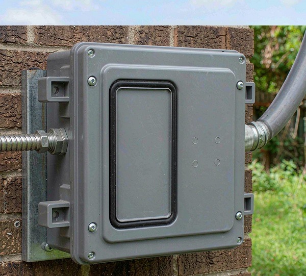
Street lighting, sensors, signage and telecom terminations exposed to weather.
Underground infrastructure
Traffic, utility and telecom pits where standing water is expected.
Marine
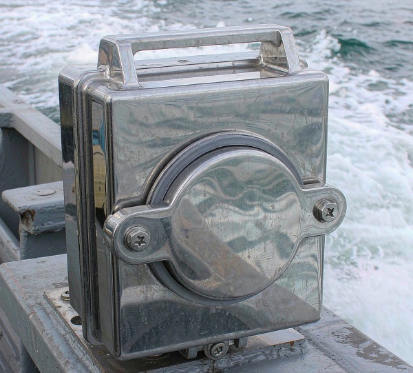
Boat electronics and deck enclosures near spray and bilge.
Industrial
Factory floor control boxes facing washdown and coolant.
Renewable energy
Solar combiner and wind yaw boxes in exposed sites.
Customization Scope
What we set per order versus what needs separate validation:
- Dimensions, wall thickness, cover type — yes
- Gland count, diameter, thread, position — yes
- Threaded inserts, bosses, holes, brackets — yes
- DIN rail, PCB standoffs, terminals — yes
- Color and laser labeling — yes
- Explosion-proof / ATEX rating — only with separate certification; not assumed
Manufacturing Options
One enclosure, several routes. We pick the process from your volume and material, then handle finishing and assembly in-house.
Injection molding
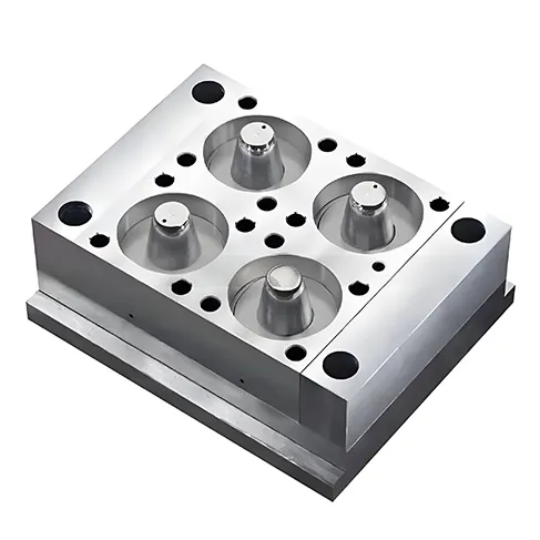
ABS and PC bodies for production volume. See our injection molding process.
Die casting
Aluminum housings for EMI shielding and rigidity.
CNC machining
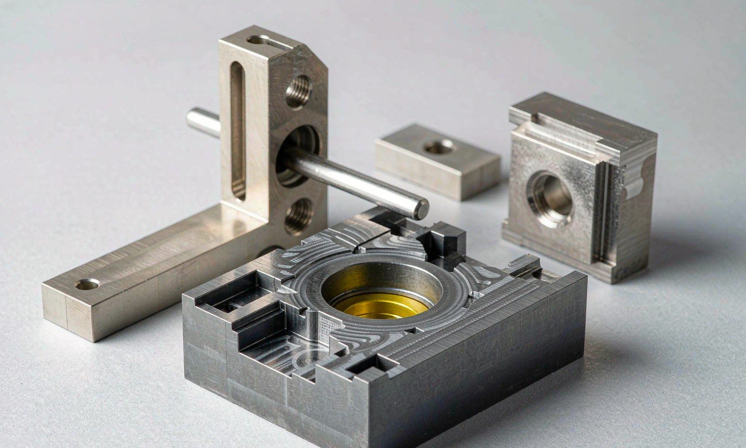
Low-volume and metal prototypes, holes and inserts.
Secondary & assembly
Drilling, tapping, gland fit, DIN rail and test.
Representative Configuration
A typical build we support: an outdoor solar combiner enclosure, 320 × 240 × 120 mm in glass-filled polycarbonate, four M20 brass glands, 35 mm DIN rail with terminal blocks, transparent cover, IP68 validated at 1 m / 24 h per the customer's declared condition, 500-piece lot, 20-day lead. Figures are a configuration example used to show scope — not a referenced customer project.
Frequently Asked Questions
What is an IP68 junction box?
Do I need IP66 or IP68?
Can the box be customized to my drawing?
Which housing material should I choose?
How do cable glands affect the IP68 rating?
Can I specify cable-entry positions?
Are these suitable for underground or marine use?
What information do you need to quote?
Final Product Specification
| Protection | IP66 standard; IP68 to customer-declared immersion condition |
|---|---|
| Materials | ABS, PC, aluminum, stainless steel 304/316 |
| Size | 53 × 55 × 37 mm to 400 × 600 × 185 mm; custom ≤1200 × 800 mm |
| Cable entry | 2–6 glands, Ø 6–32 mm, metric or PG, drawn positions |
| Internal | DIN rail, PCB standoffs, terminals, bosses, clamps |
| Cover | Solid or transparent PC |
| Finish | Corrosion-resistant; salt-spray per ASTM B117 / ISO 9227 on request |
| Quality | Built under one ISO 9001:2015 system |
Built by Xiamen Goldcattle Plastic & Metal Products Co., Ltd. — Founded in 1998, one OEM/ODM supplier for molded, cast and machined enclosures.