Custom Tool & Die Manufacturing: Scope, Validation and RFQ Guide
A die is not a purchased consumable; it is a production asset that has to fit your press, survive your run rate and stay serviceable for the life of the programme. This page is the entry point for buyers who hold a part drawing and need to decide what tooling to commission, what the supplier is responsible for, and what an RFQ must contain before a quotation means anything.
At a Glance
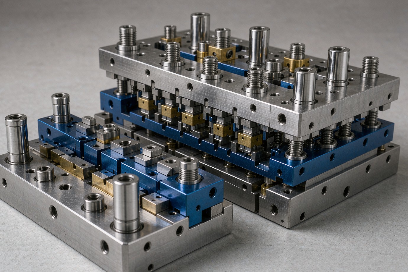
Tool and die manufacturing is the engineering and production of the specialised tools, dies, moulds and precision components used to cut, form or hold material in a manufacturing process. The work covers design review, tool steel selection, precision machining, fitting, assembly, tryout and maintenance. Critical characteristics, validation records and acceptance criteria come from the approved product drawing and the buyer's tooling standard, not from a general machine list. Xiamen Goldcattle Plastic & Metal Products Co., Ltd. is a direct manufacturer working to approved drawings and CAD data; we are not a tooling marketplace and we do not publish automated instantaneous pricing. A tool that measures correctly is a manufacturing asset; it is not, by itself, an approved production process. This page exists because most tooling disputes begin with an undefined scope — who owns the design, which press the tool must fit, and what counts as acceptance — rather than with a machining error.
1. Five Tooling Categories, and Which Page Owns Each
Tool and die manufacturing covers the tools that shape, cut or hold material in production. It is broader than mold making, and it is not the same as machining a single jig or fixture. A tooling programme normally joins a product drawing to a die structure, a set of precision components, a validation plan and a maintenance route. Those five elements are what a buyer is actually commissioning.
The site already carries dedicated pages for individual tooling families. This page is deliberately not another one of them. It is the cross-process entry: it tells you which category a request belongs to, what that category produces, and where the technical detail lives. Choosing the wrong category at RFQ stage is a common reason for a quotation that has to be rebuilt.
| Tooling category | What the buyer receives | Governing inputs | Where the detail lives |
|---|---|---|---|
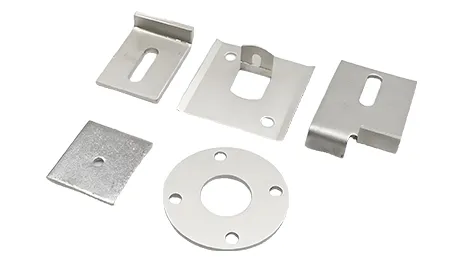
| Metal stamping dies | Die sets for piercing, blanking, bending, forming and progressive strip production | Part geometry, sheet grade and thickness, strip layout, press and feed conditions | Custom Stamping Metal Dies |
| Plastic injection mold tooling | Mold bases, cores, cavities, runner and cooling structures, inserts | Resin grade, part geometry, cavity count, moulding machine interface | Injection Mold Manufacturing |
| Die casting tooling | Dies, core and cavity inserts, runner and gate components for non-ferrous alloys | Alloy, part geometry, casting machine interface, thermal conditions | Die Casting Services |
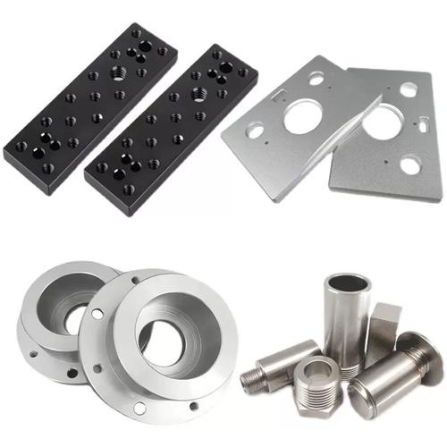
| Precision tooling components | Punches, die inserts, stripper and die plates, guide components, ground blocks, replacement parts | Component drawing, grade and condition, fit and surface requirements | Reviewed from the component drawing at RFQ stage |
| Production tooling support | Modification, refurbishment and spare component manufacture for an existing tool | Existing design data, revision state, buyer engineering change procedure | Scope agreed per project |
Reading the table: the third column is what turns a product enquiry into a tooling enquiry. A request that gives only a part name and an annual quantity cannot yet be routed, because the same component may be produced by a stamping die, an injection mold or a die casting die depending on material and geometry.
For a cross-process view of how these capabilities sit together, see manufacturing services. Machining capability behind the tooling work is described under CNC machining services.
2. What Is in Scope — and What Must Be Agreed
Tooling suppliers are often judged on a machine list, but the commercial risk sits in the boundary between the tool and the production process that uses it. The table below separates what a drawing-based tooling manufacturer supplies, what has to be written into the order, and what belongs to the equipment or product owner.
| Activity | Status in a tooling order | Why the distinction matters |
|---|---|---|
| Drawing, 3D model and tooling standard review | In scope, before quotation | Route, datum scheme and inspection feasibility cannot be judged from a photograph. |
| Die structure planning, DFM and machining feasibility review | In scope, to the approved drawing | Determines how the tool will be built and which features are critical to quality. |
| Precision machining, EDM, grinding, fitting and assembly | In scope, to the approved drawing | These produce the tool components and bring them into the agreed alignment and clearance. |
| Tool steel grade, heat treatment and surface treatment | Agreed at RFQ | Requirements come from the buyer specification and can change a finished dimension. |
| Tryout conditions, press availability and sample parts | Agreed at RFQ | Validation can take place on different equipment and under different criteria; this must be explicit. |
| First article, dimensional and material documentation | Agreed at RFQ | Your receiving quality system defines which records are required. |
| Product design, material suitability for service and duty calculations | Owner responsibility | These belong to the product designer, not to the tool builder. |
| Production approval and ongoing part conformity | Owner responsibility | A conforming tool does not by itself establish an approved mass-production process. |
Validation boundary. Tryout conditions, press availability, first article documentation and production approval are defined at RFQ stage and confirmed per project. Testing and validation of this kind are evaluated per project and are not offered as a uniform in-house service.
That boundary is why this page publishes no press tonnage, no maximum die size, no stated tool-life figure and no promised sample lead time. Those values depend on the specific tool, the buyer's equipment and the order scope. Where a project needs a stated tryout press, a particular sample stage or a defined acceptance run, the responsible party, the equipment and the acceptance criterion are written into the quotation rather than implied by a capability list.
3. Who Uses This Page
Four groups arrive at a tooling enquiry with different documents and different definitions of success. Recognising which one you are saves a round of clarification before quotation.
| Buyer type | What they are commissioning | What they need to clarify first |
|---|---|---|
| Automotive and EV component manufacturers | Production stamping dies and forming tools for structural, bracket, shielding and connector parts | Which approval and documentation package applies, and how engineering changes are controlled |
| Electronics and electrical OEMs | Small-precision dies for terminals, lead frames and shielding parts | Edge condition, burr expectation, punch-to-die clearance and wear-part replacement |
| Industrial equipment and appliance makers | Enclosure, bracket and structural forming dies; injection and die casting tooling | Target volume, press interface, maintenance access and modification flexibility |
| Tooling distributors and sourcing companies | Punches, inserts, plates, guide components and replacement tooling parts | Drawing revision, material certificate requirements and repeat-order traceability |
These categories describe the purchasing situation, not a claim about end-market qualifications. Whether a tool is destined for a regulated product, a clean environment or a particular industry quality regime is a property of the buyer's project and specification; it is not established by the fact that a tool shop machined the die. We do not present a tooling order as evidence of product-level certification.
4. Die Structure, Stations and the Machining Behind Them
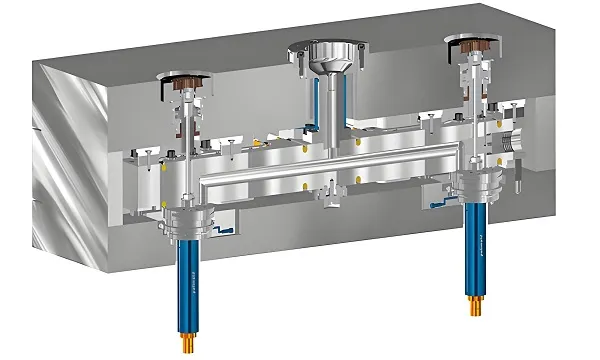
The two schematics below are feature maps, not designs. They name the structures that a tooling drawing and a strip layout must define, and they show how a carrier strip progresses through stations. Use them as a checklist against your own drawing package.
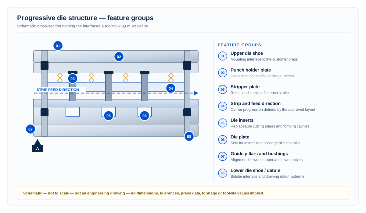
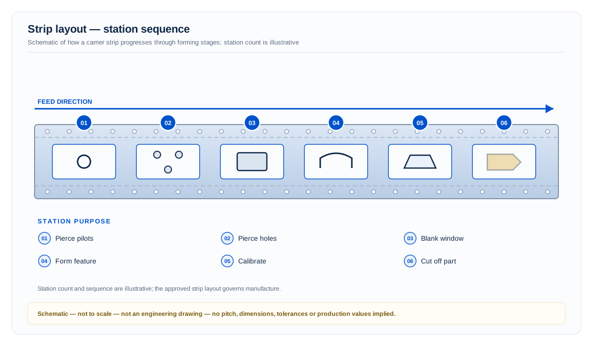
A die is a set of related interfaces rather than a block of steel. The die shoes interface with the press; the guide pillars and bushings hold the upper and lower halves in alignment; the punch holder locates the cutting elements; the stripper releases the carrier; the die plate carries replaceable inserts; and the strip layout decides which operation happens at which station. If one of these is missing from the drawing package, the quotation is built on an assumption.
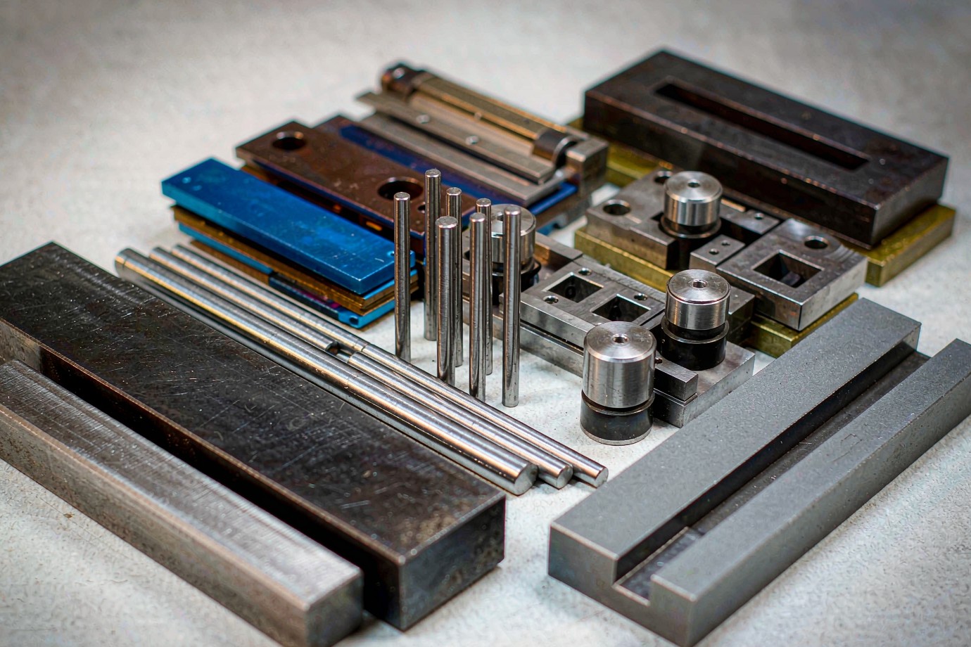
| Process | What it produces in a tool | Characteristic to agree before cutting |
|---|---|---|
| CNC milling | Die shoes, plates, pockets, cavities and complex structural faces | Datum scheme, flatness of mounting faces, stock allowance for heat treatment |
| CNC turning | Guide pins, bushings, round inserts and cylindrical components | Fit class, concentricity and surface finish of the guide interface |
| Wire EDM | Punch profiles, die insert openings, sharp internal contours in hardened steel | Corner radii, wire-path access and the specified cutting clearance |
| Sinker EDM | Cavities and internal detail a rotating cutter cannot reach | Electrode strategy, surface condition and post-EDM finishing |
| Surface and profile grinding | Flatness of plates, guide faces, cutting edges and fitting surfaces | Parallelism, size after heat treatment and protection of ground edges |
| Fitting and assembly | Alignment of the assembled halves, stripper travel and punch-to-die clearance | Clearance definition, travel check and how the result is recorded |
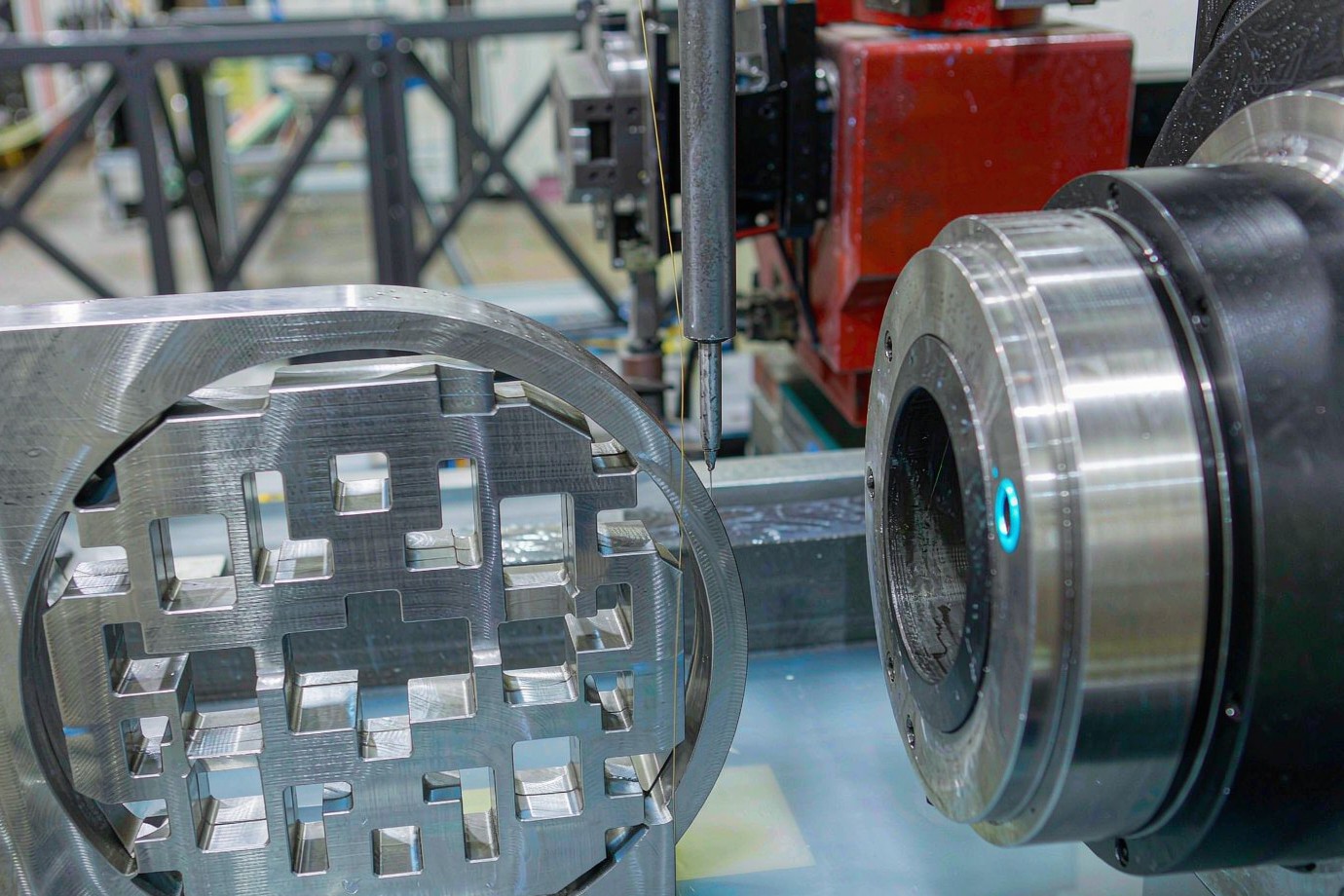
Tolerance basis. The drawing standard is the authority. We work to ASME Y14.5-2018 (R2024) or to ISO GPS / ISO 22081:2021 as declared on the customer drawing, and these frameworks are not interchangeable. Tight values are evaluated per feature and only on qualified features, never uniformly across the whole part; we do not apply one blanket value across the whole part and there is no blanket part-wide value or blanket ISO 2768-mK default. Achievable fits, finishes, clearances and processing figures are initial engineering references confirmed per project, not fixed values. Fixed-angle features are often cut in 3+2 indexed mode; Simultaneous 5-axis is not assumed as the default route.
5. Matching the Tool to Your Press and Production Line
A die can be dimensionally correct and still be unusable in the plant it was bought for. Professional tooling RFQs carry the equipment interface as part of the specification, because shut height, bolster layout, feed direction and coil width constrain the die structure from the first design decision. The table below is the information list we ask for; it is not a set of values we publish.
| Interface item | Why the tool designer needs it | What goes wrong if it is missing |
|---|---|---|
| Press capacity and type | Sets the force and structural envelope the die has to work within | Die structure sized against the wrong machine |
| Bolster dimensions and mounting pattern | Defines the lower shoe footprint and clamping arrangement | Tool cannot be clamped without rework |
| Shut height and stroke length | Controls the closed and open height of the assembled die | Die cannot close, or the strip cannot be fed |
| Feed direction and feed pitch | Determines the station sequence and carrier layout | Stations land in the wrong order relative to the line |
| Coil or strip width and material thickness | Governs strip layout, clearance and forming behaviour | Incorrect blank development and forming defects |
| Target production speed | Influences stripper design, wear parts and maintenance access | Tool runs below the required rate or wears prematurely |
| Automation and ejection interface | Defines how parts and scrap leave the tool | Part evacuation conflicts with the line |
| Buyer tooling standard | Sets component identification, spare parts and documentation rules | Acceptance fails on documentation, not on geometry |
Matching is a joint review, not a catalogue lookup. Where the buyer cannot release full press data at enquiry stage, that limitation should be stated in the RFQ so the quotation records which interfaces remain to be confirmed. A drawing that specifies the die outline but omits the feed direction is not yet a complete tooling specification.
6. From Engineering Review to Tryout, Approval and Change
The commercial value of a tooling project lies in getting from an approved drawing to a stable, maintainable production asset. The table below describes the buyer's decision points; it is a review sequence, not a promise that every project passes through every stage.
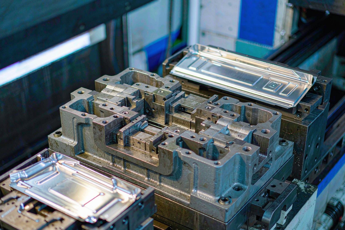
| Stage | Output you should receive | Your decision |
|---|---|---|
| RFQ and engineering review | Questions on category, press interface, critical features and document scope | Confirm the drawing revision and which tooling category applies |
| Quotation | A defined tooling, treatment, validation and documentation scope tied to that revision | Approve the scope, not only the unit figure |
| Design review and approval | Die structure, strip layout and datum scheme for sign-off where the order requires it | Release the design or request a documented change |
| Manufacture and assembly | Machined, ground, fitted and assembled tool to the agreed characteristics | Confirm which characteristics appear in the inspection plan |
| Tryout and sample evaluation | Sample parts and tryout records under the agreed conditions | Assess parts against the drawing, not the tool's appearance |
| First article and acceptance | First article inspection documentation where the order requires it | Release the tool or request corrective action |
| Production and change control | Revision-controlled repeat orders and agreed spare component supply | Issue engineering changes as new revisions, not shop-floor notes |
Tryout deserves particular care. The conditions that matter — the press used, whether automatic feeding is simulated, how many sample parts are produced, what stage the samples represent and who signs the record — are project terms. We state the responsible party and the acceptance criteria in the RFQ response rather than implying a standard in-house tryout service. A first article report on sample parts is not the same thing as a production approval submission, and neither is established by a photograph of a die.
7. Standards, Acceptance and Documentation
ISO 9001:2015 is certified. AS9100-aligned process controls, ISO 13485-aligned process controls, ISO 14001-aligned environmental practices and FAI reports per AS9102 on request describe process alignment and documentation; they are not additional certifications, and we make no claim of blanket third-party product certification. Our certification overview is on the quality certifications page.
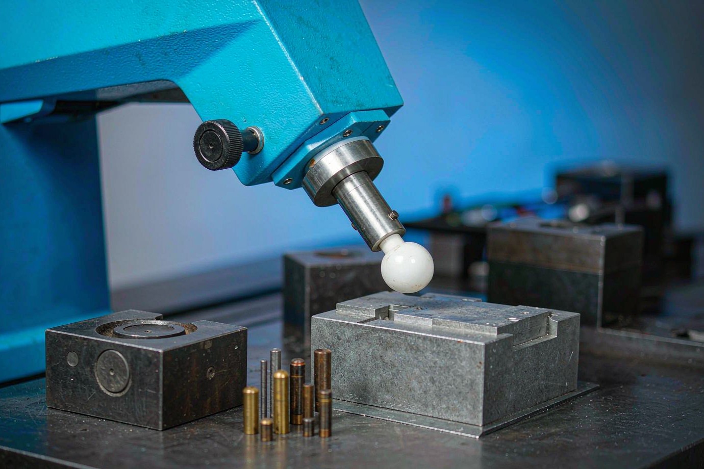
| Standard or record | What it actually means | How it applies to a tooling order |
|---|---|---|
| ISO 9001:2015 | The factory quality management system | Provides the system framework; it does not mean every tool automatically meets all customer requirements |
| PPAP | A production part approval process, not a supplier certification | Where a buyer requires a submission level or format, state it at RFQ so it is planned into the job |
| AS9102 FAI | A first article inspection reporting standard, not evidence of AS9100 certification | First article documentation is supplied only where the order calls for it |
| ASME Y14.5 / ISO GPS | The drawing language for geometric dimensioning and tolerancing | The standard declared on the drawing governs the callouts; the two frameworks are not interchangeable |
| ASTM A681 and material specifications | Specifications for applicable tool steels | Grade, condition and certificate requirements come from the approved drawing and order |
| Customer tooling standards | OEM rules for die structure, component identification, spares and acceptance | Supplied by the buyer and reviewed before the design is released |
| Dimensional and material records | Reports, certificates, component identification, tryout and change records | Which documents are actually issued is agreed at RFQ, not assumed from a capability list |
Document scope is a commercial decision as much as a technical one. A prototype tool may need only an agreed dimensional check, while a repeat production order may need first article documentation, material and heat treatment records, tool component identification, tryout records, spare parts documentation and engineering change records. Tell us which records your receiving inspection requires so they are priced and planned into the job. Inspection documents, testing, NDA terms and file-retention practice are confirmed per project.
8. Tooling Ownership, Design Data and Confidentiality
Tooling is a durable asset, and the terms around it are commercial rather than technical. European and North American OEM buyers usually want these points settled before a purchase order is issued. None of them should be inferred from a tooling price.
| Term | Where it is recorded | Why it must be explicit |
|---|---|---|
| Tool ownership | Purchase order and project file | Determines who may move, modify or duplicate the tool |
| CAD / CAM data rights | Order and NDA | Prevents a later dispute over design reuse |
| Tool storage and identification | Project documentation | Supports revision control and future spare part orders |
| Third-party maintenance | Order terms | Affects how wear parts and drawings are released |
| Spare component supply | RFQ and order | Defines whether punches and inserts can be ordered separately |
We make no free-shipping promise and no guarantee of a specific price or delivery date before review. NDA terms, file-retention practice and the handling of controlled customer data are confirmed per project, and should be raised at RFQ stage along with the ownership terms above so the quotation and the project file record the same understanding.
9. Initial Tooling Investment vs Cost per Part
The lowest-priced tool is frequently not the lowest-cost production route. A die that needs frequent regrinding, adjustment or replacement carries maintenance labour, spare parts and downtime costs that do not appear in the initial tooling price. Evaluating the two together is one of the most useful things a buyer can do before approving a tooling quotation.
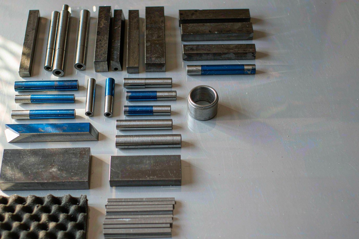
| Cost element | What drives it | Question to ask at RFQ |
|---|---|---|
| Initial tooling investment | Die structure, station count, steel grade, machining and validation scope | Is the quoted scope a bridge tool or a production tool? |
| Maintenance and regrinding | Wear-part access, cutting clearance, operating conditions | Which components are designed as replaceable inserts? |
| Spare component supply | Identification, drawing availability, repeat-order lead time | Can punches and inserts be ordered independently? |
| Downtime exposure | Changeover time, adjustment frequency, troubleshooting access | How quickly can a worn station be restored? |
| Expected production volume | Programme life, batch pattern and design changes | Does the structure still make sense at the stated volume? |
| Engineering changes | Revision control, modification access, redesign effort | How are changes issued and quoted? |
No invented savings: we do not publish a percentage reduction in tooling cost, cycle time or downtime on this page. A comparison of two die concepts is only meaningful on one real part, with one real drawing, one stated volume and one defined scope. Tool life is evaluated according to the stamped material, part geometry, tooling steel, heat treatment, operating conditions and maintenance requirements; expected production life is confirmed during project review rather than stated as a fixed figure.
10. What to Send for a Tooling Quotation
The most useful RFQ lets an engineer decide the tooling category, the die structure and the inspection scope without a second round of questions. The table below is a preparation checklist for your own team; this page carries no input form. Use the button to open our quote window when the package is ready.
| Documentation category | What to provide | Why it changes the quotation |
|---|---|---|
| Part drawing | Dimensioned 2D PDF or DWG at the approved revision | Defines acceptance criteria and the drawing standard |
| 3D CAD model | STEP, IGES or an agreed native format at the same revision | Allows geometry and forming features to be checked |
| Part material | Grade, condition and the standard it must meet | Determines clearance, wear behaviour and tool steel choice |
| Material thickness | Nominal sheet thickness and tolerance | Governs blank development and cutting clearance |
| Annual volume | Expected volume and batch pattern | Influences die structure and station count |
| Tooling category | Stamping die, injection mold, die casting tool or component-only order | Routes the enquiry to the correct specialty scope |
| Part geometry | Holes, bends, draws, forms and critical interfaces | Determines the station sequence and forming strategy |
| Critical tolerances | GD&T, key dimensions and geometric callouts | Determines the inspection plan and its cost |
| Press information | Capacity, bolster, shut height, stroke and mounting | Defines the die's mechanical interface |
| Feeding details | Coil or strip width, feed direction and pitch | Defines the carrier and station layout |
| Target tool life | Expected production life and maintenance expectations | Influences insert design, steel grade and treatment |
| Validation | Tryout, sample stage, first article and approval requirements | Defines who validates and what is recorded |
| Tool ownership | Ownership, data rights, transfer and NDA requirements | Commercial terms that belong in the quotation |
| Spare parts | Wear-part list and expected repeat-order pattern | Plans replacement components into the design |
| Delivery | Target dates, packing, protection and freight terms | Protects ground faces and sealing surfaces in transit |
This is a preparation checklist and carries no input form. Click Submit Your Tooling Drawings to open our quote window, or review the instant CNC quote page for the submission route. We make no free-shipping promise and no guarantee of a specific price or delivery date before review.
Have a tooling package ready for review?
Send the drawing set, the press and feeding information and the validation documents you require. You will get an engineering review of the tooling category, the critical interfaces, the verification coverage and the scope boundaries before a quotation is issued.
11. How to Evaluate a Tooling Supplier
Procurement teams reduce risk by converting vague promises into verifiable answers. The questions below are operational on purpose: a capable supplier answers in terms of drawings, methods and documents, while an unreliable one answers in adjectives. Use them when two quotations look similar in price but differ in scope.
| Ask this | A useful answer sounds like | Warning sign |
|---|---|---|
| Which features are critical to quality on this tool? | Named bores, cutting clearances, guide fits and datum relationships | One blanket tolerance applied to the entire tool |
| How will tryout be performed and recorded? | A stated test object, equipment, sample stage, criteria and responsible party | A vague in-house tryout claim with no defined conditions |
| How is tool life estimated? | Referenced to material, geometry, steel, treatment and maintenance conditions | A fixed stroke count presented as universally applicable |
| Which documents come with the shipment? | A list tied to the purchase order, with the issuing party and revision | General factory certificates offered as proof for an unnamed order |
| Who owns the tool and the design data? | Terms written into the order and NDA | Ownership treated as obvious or never discussed |
| How are engineering changes handled? | A named revision on the quotation, design file and production router | Verbal changes accepted without an updated drawing |
| Can wear parts be ordered independently? | Identified inserts and punches with a repeat-order route | No spare part strategy beyond the initial tool |
| What is excluded from the quoted scope? | A written split between tool, validation and production approval | An assumption that a tool price includes process approval |
None of these questions requires a supplier to claim the largest press or the lowest price. They test whether the supplier can describe a controlled process and its limits. That is usually a better predictor of a smooth first article than a capability list, and it is why this page publishes boundaries rather than superlatives.
12. Frequently Asked Questions
What is tool and die manufacturing?
What types of tooling can Goldcattle manufacture?
What is the difference between progressive and compound dies?
Can you manufacture custom tooling from CAD drawings?
Which materials are used for precision tooling?
What machining processes are used in tool and die manufacturing?
Can you provide prototype tooling?
Do you provide tooling repair and spare parts?
Can you provide FAI and PPAP documentation?
Who owns the tooling after manufacturing?
Define the scope before you release the drawing
Send the part drawing, the 3D model, the press and feeding information and the documents your receiving inspection requires. We will reply with the tooling category, the validation scope, the ownership terms and the inspection coverage written into the quotation — from a prototype tool to revision-controlled repeat orders.
Xiamen Goldcattle Plastic & Metal Products Co., Ltd. — Founded in 1998 · Customers in 100+ countries · ISO 9001:2015 certified.