Three Core Additive Technologies
Each process deposits material differently — and each introduces distinct failure modes. Knowing the underlying mechanism helps you diagnose root causes faster.
Thermoplastic filament is heated to a semi-liquid state and extruded through a precision nozzle, depositing material layer by layer onto a build platform. Layer adhesion depends on thermal gradient control.
A UV laser or projected light pattern selectively cures liquid photopolymer resin in a vat. The cured layer solidifies, and the platform lifts for the next layer. Peel forces between cured part and vat floor are a primary failure source.
A high-power laser fuses powdered material (typically PA12 nylon) within a heated build chamber. Unsintered powder acts as self-supporting material, eliminating support structures entirely. Thermal uniformity is critical.
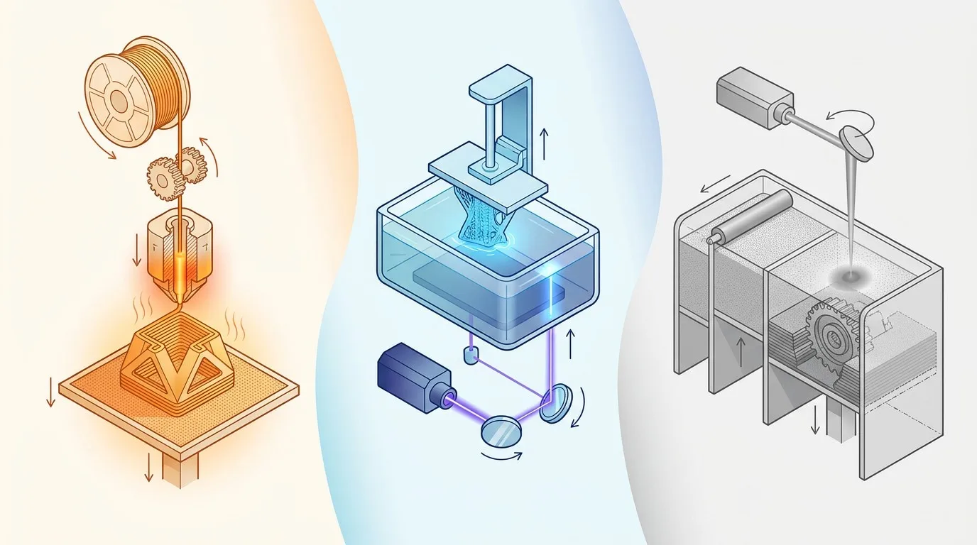
Technology comparison: FDM filament extrusion (warm tones), SLA resin curing (blue tones), SLS powder bed fusion (gray tones)
Common Failure Categories & Root Causes
Each failure below is presented with symptom identification, underlying cause, and actionable resolution steps.
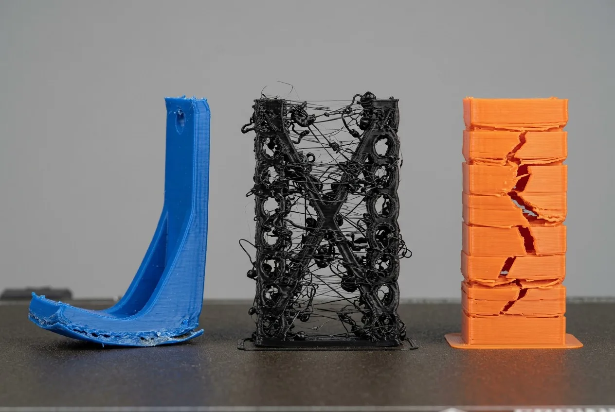
Left: corner warping (ABS); Center: stringing between gaps; Right: layer delamination
Bed Adhesion & First Layer Failures
Why it matters: The first layer anchors the entire build. Adhesion depends on surface energy, temperature gradient, and Z-offset calibration. A poorly bonded first layer propagates defects upward through every subsequent layer.
Symptoms: Print lifts at corners, first layer appears ragged or skips lines, part slides on the build plate mid-print.
Root cause — Surface energy mismatch: Filament must wet the build surface. PEI sheets provide high surface energy for most thermoplastics. Glass requires adhesive agents (glue stick, hairspray). The Z-offset must create a slight squish (0.05–0.1 mm) so the extruded road spreads and bonds.
Resolution checklist:
- Paper test: set Z-offset so a standard sheet of paper slides with light resistance between nozzle and bed
- Bed temperature: PLA 50–60 °C, ABS 100–110 °C, PETG 70–80 °C, Nylon 80–100 °C
- Surface prep: clean PEI with isopropyl alcohol; apply thin glue layer on glass for ABS/PETG
- First-layer speed: reduce to 20–30 mm/s; increase flow to 105–110% for initial layer
- Brim/raft: add a 5–10 mm brim for parts with small footprints
Warping & Thermal Cracking
Why it matters: Differential cooling creates internal stress. As upper layers cool and contract while lower layers remain bonded to the heated bed, tensile forces pull corners upward. ABS and nylon — with higher coefficients of thermal expansion — are most susceptible.
Symptoms: Corners curl off the build plate; mid-print cracking with audible pops; dimensional distortion in flat parts.
Root cause — CTE mismatch & thermal gradient: ABS contracts ~0.8% upon cooling from extrusion temperature (230 °C) to ambient. In an open-frame printer, the top layers cool much faster than the bed-heated bottom, creating a bending moment that lifts corners.
Resolution checklist:
- Enclosed build chamber: maintain 40–50 °C ambient for ABS, 30–40 °C for PETG
- Part cooling fan: disable for first 3 layers on ABS; reduce to 30–50% for PETG
- Brim width: 8–15 mm for wide flat parts; raft for tall thin geometries
- Bed temp max: ABS 110 °C, Nylon 100 °C — thermal shock prevention
- Gradual cooling: lower bed temp by 5 °C increments over 10 minutes after print completes
Extrusion Issues: Under-extrusion, Over-extrusion & Stringing
Why it matters: Inconsistent extrusion directly affects dimensional accuracy, surface quality, and inter-layer bonding. Stringing wastes material and requires post-processing, adding cost to batch runs.
Symptoms: Thin or missing lines (under); bulging walls with zits at corners (over); thin wisps of filament between disconnected regions (stringing).
Root cause — Flow rate & retraction: Under-extrusion often traces to filament diameter variance (target ±0.05 mm for 1.75 mm filament), partial nozzle clogs, or incorrect extrusion multiplier. Stringing results from inadequate retraction — the nozzle continues oozing during travel moves because residual pressure in the melt chamber pushes material out.
Resolution checklist:
- Measure filament: calibrate extrusion multiplier against actual measured diameter (target 1.75 mm ±0.05)
- Retraction tuning: distance 5–7 mm (direct drive: 1–2 mm), speed 40–60 mm/s; reduce extra restart amount
- Nozzle maintenance: cold pull at 180 °C with nylon filament; replace brass nozzle after ~50 kg of abrasive filament
- Temperature: lower by 5–10 °C to reduce oozing; PLA 190–210 °C, PETG 230–250 °C
- Travel speed: increase to 150–200 mm/s to minimize ooze time
Layer Shifting & Mechanical Misalignment
Why it matters: Shifted layers produce geometrically inaccurate parts — unacceptable for functional prototypes and assemblies where dimensional tolerance matters.
Symptoms: Visible horizontal offset at a specific layer; entire upper section displaced in X or Y direction; staircase effect on vertical walls.
Root cause — Mechanical overload or belt slip: When acceleration or print speed exceeds the stepper motor’s torque capacity, the motor skips micro-steps. Loose drive belts allow pulley slip under load. Collisions with curled or shifted previous layers can also trigger sudden displacement.
Resolution checklist:
- Belt tension: tighten XY belts until a light pluck produces a low hum, not a slack rattle
- Acceleration limit: reduce to 500–1000 mm/s² for heavy assemblies; jerk to 8–12 mm/s
- Print speed: cap at 60 mm/s for precision parts; outer walls at 30–40 mm/s
- Current calibration: verify stepper motor current matches driver rating — too low causes skips
- Lubrication: apply light machine oil to linear rods; check Z-axis lead screw for binding
Resin-Specific Failures (SLA / DLP)
Why it matters: Resin printing delivers unmatched resolution, but peel forces, exposure calibration, and support strategy introduce unique failure vectors not found in filament-based processes.
Symptoms: Part detaches from supports mid-print; hollow sections collapse; suction cup failures on flat surfaces; resin bleeding into fine features.
Root cause — Peel force & exposure mismatch: As the build platform lifts, cured resin must separate from the FEP film at the vat bottom. Large flat areas create vacuum-lock (suction cup effect). Under-exposure yields weak layers that detach; over-exposure bloats fine details.
Resolution checklist:
- Exposure calibration: run validation matrix — typical normal layers 6–10 s, bottom layers 30–50 s
- Anti-suction: add drain holes (≥2 mm) to hollow models; orient flat surfaces at 30–45° tilt
- Support density: increase tip size (0.4–0.6 mm) for heavy sections; use light supports for delicate features
- FEP condition: replace warped or scratched FEP films — surface defects amplify peel forces
- Resin temperature: maintain 25–30 °C; cold resin increases viscosity and peel stress
Design-for-Additive Failures
Why it matters: Geometry that violates process constraints forces excessive supports, weak inter-layer bonds, or impossible builds — the failure is baked into the CAD file before printing begins.
Symptoms: Sagging overhangs despite supports; fragile thin walls that crack; fused holes due to insufficient clearance; visible support scars on critical surfaces.
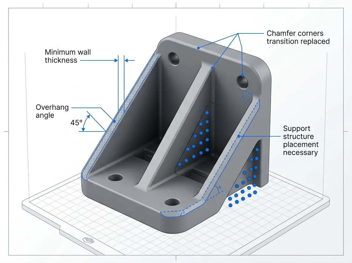
DfM reference: wall thickness, overhang angles, and chamfer transitions
DfM resolution checklist:
- Minimum wall thickness: FDM 1.5–2 mm, SLA 0.6–1 mm, SLS 0.8–1 mm
- Overhang rule: FDM supports required beyond 45° from vertical; SLA tolerates up to 60° with proper support
- Clearance: maintain ≥0.4 mm between mating surfaces for FDM; ≥0.2 mm for SLA assemblies
- Hole orientation: horizontal holes distort — orient vertically when precision is required
- Chamfer over fillet: sharp transitions print more reliably than smooth curves on FDM
Material & Process Parameter Reference
Optimal parameters vary by material class. Use this reference as a starting point, then fine-tune for your specific machine, geometry, and ambient conditions.
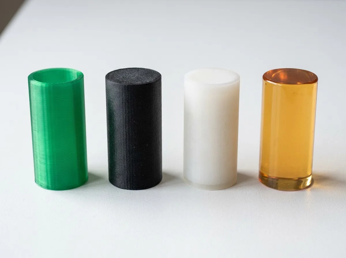
Material specimen comparison — surface texture and translucency differences across PLA, ABS, PA12, and Resin
| Parameter | PLA | ABS | PETG | Nylon PA12 | Resin (Standard) |
|---|---|---|---|---|---|
| Nozzle / Extrusion Temp | 190–210 °C | 230–250 °C | 230–250 °C | 240–270 °C | N/A (UV) |
| Bed Temperature | 50–60 °C | 100–110 °C | 70–80 °C | 80–100 °C | N/A |
| Print Speed (outer wall) | 30–40 mm/s | 30–50 mm/s | 30–40 mm/s | 20–40 mm/s | N/A |
| Part Cooling Fan | 100% | 0–30% | 30–50% | 0–20% | N/A |
| Moisture Sensitivity | Low | Moderate | Low | Very High | Low |
| Min. Wall Thickness | 1.5 mm | 2 mm | 1.5 mm | 2 mm | 0.6 mm |
| Overhang (no support) | ≤ 45° | ≤ 45° | ≤ 45° | ≤ 45° | ≤ 60° |
| Post-Processing | Sanding, primer | Vapor smoothing | Sanding, flame | Dyeing, machining | IPA wash, UV cure |
Moisture advisory: Nylon PA12 absorbs moisture at 1.5–2% by weight within 48 hours at 50% RH. Wet filament produces steam bubbles during extrusion, resulting in porous, weak layers with visible micro-bubbles. Always store nylon in sealed containers with desiccant packs, and dry at 80 °C for 4–6 hours before printing.
Process Comparison: Which Technology Fits Your Application?
Selecting the right technology prevents failures before they occur. Each process excels in specific applications — mismatched technology choice is itself a failure mode.
| Criteria | FDM | SLA / DLP | SLS |
|---|---|---|---|
| Resolution (XY) | 0.4–0.8 mm | 0.025–0.05 mm | 0.1 mm |
| Layer Height (Z) | 0.1–0.3 mm | 0.025–0.1 mm | 0.1 mm |
| Surface Finish | Visible layer lines | Near-injection mold | Slightly grainy |
| Support Requirement | Yes (removable) | Yes (breakaway) | No (powder self-support) |
| Material Range | Wide (PLA to PEEK) | Resins only | PA12, TPU, PA11 |
| Mechanical Strength | Anisotropic (Z weak) | Brittle (UV aging) | Near-isotropic |
| Batch Production Cost | Low per unit | Moderate | Economical at volume |
| Best Application | Functional prototypes, jigs, fixtures | Dental, jewelry, micro-features | Complex geometries, end-use parts |
Case Study: Reducing Failure Rate from 25% to Below 5%
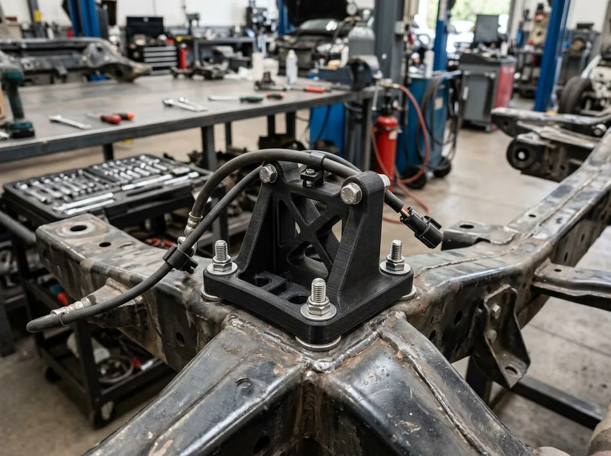
Functional 3D printed ABS bracket in automotive chassis application
The Challenge
An EU automotive tier-1 supplier was producing custom sensor brackets via desktop FDM printers for rapid prototype validation. Failure rate averaged 25% — primarily warping on ABS parts, stringing on PETG housings, and inconsistent first-layer adhesion. Each failed iteration consumed 4–6 hours of machine time and $15–30 of material, delaying design review cycles by 2–3 days.
The Resolution
Parameter optimization across three variables — bed temperature, retraction settings, and enclosure environment — combined with DfM revisions (chamfers replacing fillets, 2 mm minimum walls, drain holes in hollow sections). After 5 calibrated test prints, the failure rate dropped below 5%. Material waste reduced by 80%, and prototype turnaround improved from 3 days to under 24 hours.
Key takeaway: Systematic parameter tuning — rather than ad hoc adjustments — transforms failure-prone desktop printing into a reliable rapid-prototyping pipeline. When internal resources cannot resolve persistent issues, engaging a professional additive manufacturing service accelerates the diagnostic-to-resolution cycle.
Advanced Prevention Strategies
Beyond basic parameter tuning, these strategies address systemic reliability for production-scale additive manufacturing.
FEA-based thermal distortion simulation predicts warping and residual stress before material is committed. Tools like Autodesk Netfabb or Materialise Magics generate compensated geometry that counteracts anticipated shrinkage — reducing physical iterations by 40–60%.
Thermal cameras and acoustic sensors detect layer-level anomalies mid-print: unexpected temperature drops, nozzle collision sounds, or inconsistent extrusion patterns. Early detection enables automatic pause-and-adjust, salvaging builds before total failure.
Maintaining a structured failure log — documenting material, geometry, parameters, ambient conditions, and failure type — enables statistical root-cause analysis. Patterns emerge after 20–30 entries, revealing machine-specific or material-specific tendencies.
Application-Specific Considerations
Medical devices: Biocompatible resins (Class IIa) require validated exposure parameters and post-curing protocols. Dimensional tolerance ±0.1 mm is non-negotiable. Sterilization compatibility must be verified per material datasheet.
Aerospace components: UL94 V0-rated materials for interior parts; flame resistance testing per FAR 25.853. Traceability requires material lot documentation and parameter logging per build.
Functional prototypes: Mechanical testing (tensile, flexural) reveals anisotropic weakness in Z-direction. Heat treatment (annealing at 80 °C for PLA) can reduce internal stress and improve dimensional stability by 30–50%.
When Internal Printing Fails: Professional Service Advantages
Persistent failures signal a gap between in-house capability and production requirements. Professional additive manufacturing services close that gap with calibrated equipment, quality systems, and process expertise.
Industrial-grade printers with enclosed chambers, automatic bed leveling, and monitored build environments. Parameter drift is eliminated through scheduled calibration cycles.
ISO 9001-certified processes. Every build undergoes dimensional inspection with calibrated instruments. Material certifications and traceability documentation provided per shipment.
From model upload to shipped part in 3–5 business days. Batch production scaling without queue delays. DfM review included before build — catching design issues before material is committed.
Xiamen Goldcattle — Your Reliable Additive Manufacturing Partner
With 18+ years in precision custom manufacturing, Goldcattle operates FDM, SLA, and SLS capabilities alongside CNC machining and injection molding — giving you a single-source partner for prototypes through production.
FDM for functional prototypes, SLA for high-detail models, SLS for complex end-use geometries — plus CNC machining and injection molding for production scaling.
ISO 9001 certified. Material certifications on request. Dimensional inspection reports with every shipment. Traceability from raw material lot to finished part.
Serving EU and North American markets with DDP shipping options. English-speaking engineering support. 24-hour response on quotes and technical inquiries.
Custom Manufacturing Process
Quick Diagnostic Checklist
Use this checklist when a build fails. Methodical diagnosis beats random parameter changes — which often introduce new problems while masking the original cause.
Before Printing
- ☐ Filament dried (especially nylon, PETG)
- ☐ Bed cleaned with IPA
- ☐ Z-offset calibrated (paper test)
- ☐ Belts tensioned
- ☐ Model orientation optimized for overhangs
- ☐ Support strategy reviewed
After Failure
- ☐ Identify failure category (adhesion / warp / extrusion / shift / resin / design)
- ☐ Log parameters used (temp, speed, fan, material, geometry)
- ☐ Adjust only ONE parameter per retry
- ☐ Verify fix with a simple test print (calibration cube)
- ☐ Document result in failure log
- ☐ If 3+ retries fail → consider professional service