Defect Analysis · 2026 Engineering Guide
Why Do Plastic Parts Develop Bubbles? Causes, Risks & Solutions
A practical troubleshooting framework for injection molded components. We analyze root causes—from trapped moisture to insufficient packing pressure—and outline actionable DFM strategies to eliminate gas pockets and voids in production.
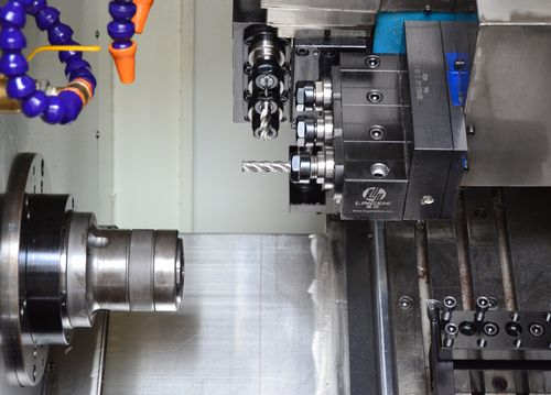
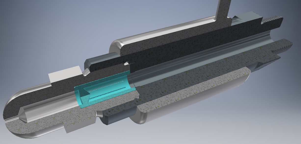 High-precision injection molding cell processing engineering-grade polymers
For buyers and project managers
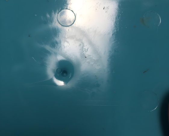
Plastic components develop bubbles primarily due to trapped gas, un dried resin moisture, excessive wall thickness, insufficient packing pressure, or poor mold venting. Depending on their location, these voids can compromise aesthetics, structural integrity, sealing performance, and overall product reliability.
Common Causes of Bubbles in Plastic Parts
Diagnostic matrix mapping root causes to visual symptoms and severity.
| Root Cause | Typical Symptoms | Risk Level | Recommended Action |
|---|---|---|---|
| Moisture in Resin | Internal voids, splay marks | High | Desicant dry material to spec |
| Low Packing Pressure | Surface sink, deep voids | Medium | Increase hold pressure/time |
| Thick Wall Sections | Core voids, shrinkage | High | Core out or uniform thickness |
| Poor Venting | Gas burns, trapped air | High | Add/modify mold vents |
| High Melt Temp | Degradation, dark voids | Medium | Reduce barrel profile |
Procurement Risk Analysis
Do Voids Affect Product Quality?
Gas pockets are not just cosmetic issues. Their impact scales with the application environment. Buyers must evaluate defect tolerance based on end-use requirements.
Cosmetic Parts
Visible surface blemishes lead to rejection on appliance housings.
Structural Parts
Internal cavities reduce load-bearing capacity in automotive mounts.
Medical Housings
Reliability risks in disposable devices; fails biocompatibility norms.
Fluid Systems
Micro-voids cause sealing failure in pump and valve components.
Process Parameters
Bubble Defect Troubleshooting Guide
Sequential methodology for engineers to isolate and rectify void formation.
Diagnostic Flowchart
1
2
3
4
5
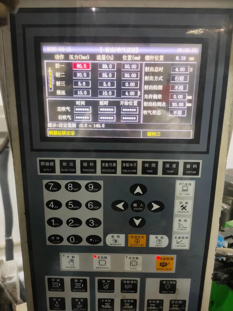
Key Parameter: Moisture Content
Engineering resins like PA66 must be dried at 80°C for 4-6 hours. Moisture turns to steam inside the barrel, causing structural micro-voids.
DFM Optimization
Design Strategies to Prevent Voids
Proactive part and mold design eliminates defect formation before steel is cut.
Uniform Wall Thickness
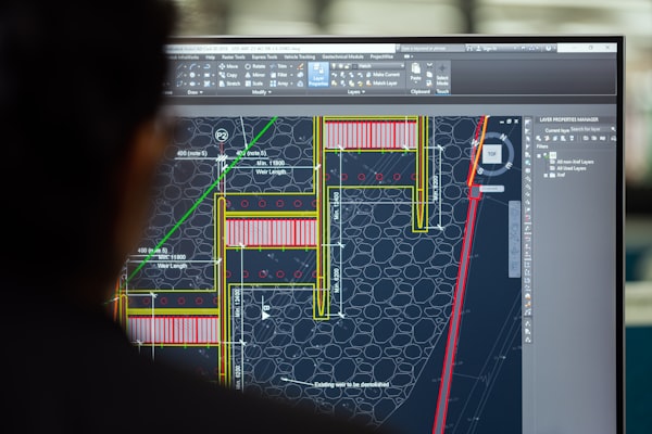
Thick sections cool slower, pulling material inward and creating vacuum cavities. Core out thick areas to maintain uniform nominal walls (typically 2-3mm).
Strategic Gate Placement
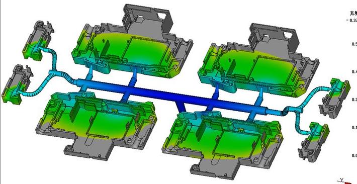
Position gates near the thickest area to ensure packing pressure compensates for volumetric shrinkage before the gate freezes off.
Proper Venting Channels
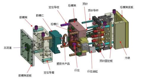
Incorporate vents at the last-to-fill areas. Ground inserts and parting lines to 0.015mm to allow trapped air escape without flash.
Rib Geometry Optimization
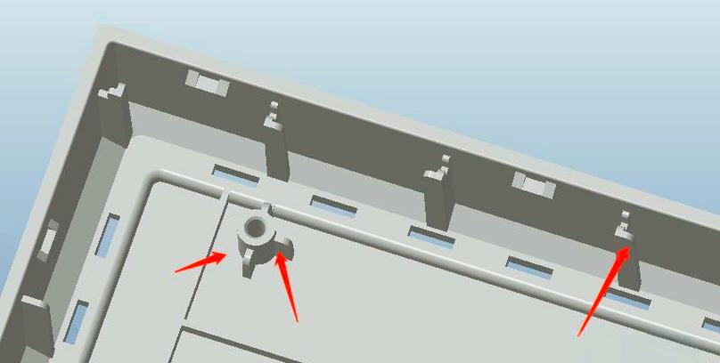
Limit rib thickness to 50-60% of the nominal wall. This prevents localized thick masses that trap gas and induce sink marks.
Real-World Applications
Defect Resolution Case Studies
How targeted process and design adjustments eliminated voiding across demanding sectors.



FAQ
Frequently Asked Questions
Why do voids form in injection molded parts?
Primarily from trapped air, undried resin turning to steam, or volumetric shrinkage in thick sections lacking sufficient packing pressure.
Are bubbles the same as voids?
Bubbles usually contain gas (air or steam), while voids are empty cavities caused by material pulling inward during cooling. Both compromise integrity.
Do bubbles affect part strength?
Yes. Internal cavities reduce cross-sectional area, creating stress concentrators that lead to premature mechanical failure under load.
Can bubbles cause leakage?
Absolutely. Micro-voids in sealing surfaces or thin diaphragms provide pathways for fluid or gas permeation, failing pressure tests.
How can moisture create bubbles?
Hygroscopic resins absorb ambient humidity. Inside the hot barrel, water boils into steam, expanding rapidly and getting trapped as the plastic freezes.
What materials are most susceptible to bubbles?
Hygroscopic engineering plastics like Polycarbonate (PC), Nylon (PA), and PET. Also, glass-filled compounds trap air between fiber bundles.
How do you prevent bubbles in transparent parts?
Strict resin drying, slightly lower melt temperatures to avoid degradation, and high packing pressure to compress any micro-gas pockets.
Can mold design cause bubble defects?
Yes. Incorrect gate locations, inadequate venting channels, and sharp corner radii all contribute to air entrapment and gas burns.
How are bubble defects detected?
Visual inspection for surface signs, cross-sectioning for internal paths, and non-destructive X-ray/CT scanning for critical production batches.
What quality controls prevent bubble formation?
Material moisture monitors, scientific molding parameter logs, pressure decay testing, and regular mold vent maintenance schedules.
Bubble Defect Prevention Summary
| Defect Type | Bubble / Void / Gas Trap |
| Main Causes | Moisture, Gas Entrapment, Thick Walls, Low Packing |
| Quality Impact | Appearance, Strength degradation, Sealing failure |
| Prevention Methods | Resin Drying, Mold Venting, Packing Optimization, Uniform Walls |
| Detection | Visual Inspection, X-Ray, Cross-section Analysis |
| Applicable Processes | Injection Molding, Insert Molding, Overmolding |
Experiencing quality issues with your current supplier?
Send us your drawings. Our engineers will review your design for manufacturability and eliminate defect risks.
© 2026 Xiamen Goldcattle Technology Co., Ltd. · ISO 9001 Certified Plastic Manufacturer · Serving OEMs in the US, EU and UK.