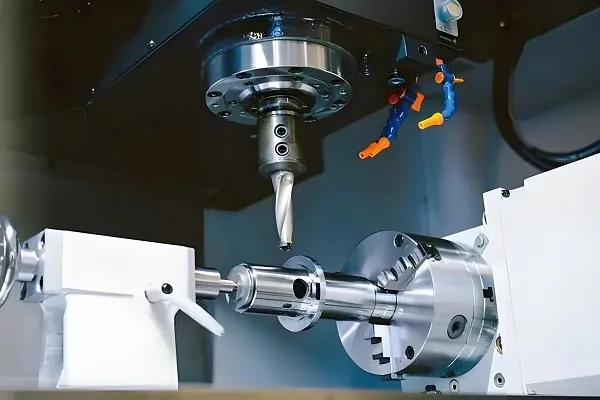
Yes. A flat end mill on a CNC mill can produce a true cube — but only if the stock is repositioned to expose all six faces, and only if the design avoids internal corners sharper than the tool can leave. The real limits are fixturing, squareness and the tolerances your drawing actually calls for, not whether the shape is possible.
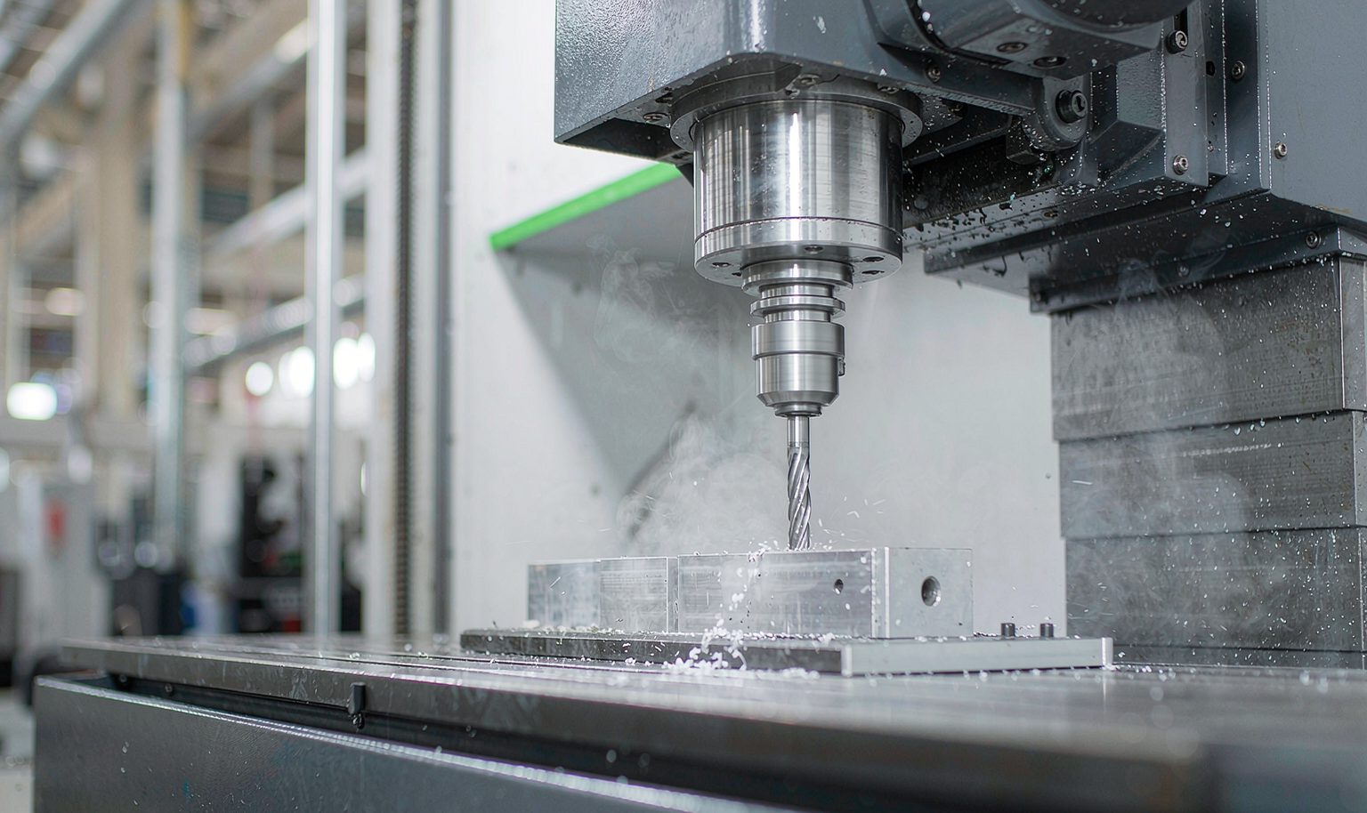
CNC Milling, Explained
Quick Answer: Yes — With the Right Setup
An end mill can absolutely make a cube. A cube is a solid with six flat faces, twelve straight edges and eight external corners. None of those features is beyond a standard 3-axis mill with a flat (square) end mill. What surprises first-time buyers is that the difficulty is not the shape — it is reaching every face and holding the faces mutually perpendicular. Get those two things right and a cube is one of the most machinable parts there is.
What “Making a Cube” Means on a CNC Mill
In machining terms, “making a cube” means starting from a rectangular blank — sawn bar stock or a rough casting — and cutting it to a specified length, width and height with controlled flatness and squareness. The blank is larger than the finished part; the mill removes the surplus through a sequence of straight cuts, each referenced to a known datum face.
The Geometry: Six Faces, Three Axes
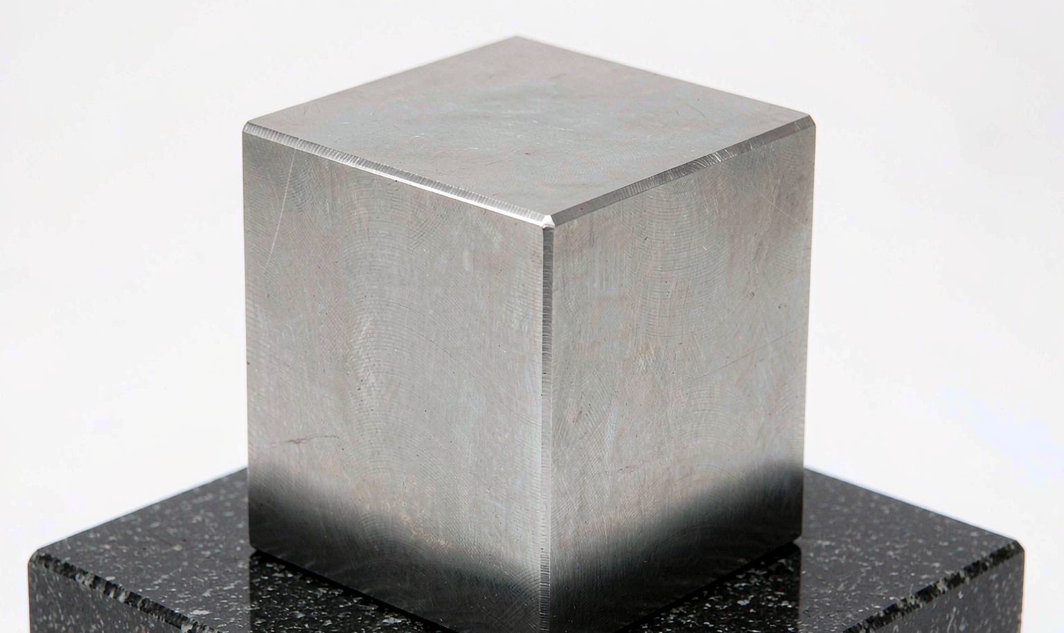
A 3-axis mill moves in X, Y and Z. Each pass cuts a face perpendicular to one axis. But a single clamping presents only three faces — the top and two sides facing the cutter; the rest are hidden by the vice. To cut all six faces you must reposition the part, and that repositioning — not the cutting — is where cubes are won or lost.
Why External Corners Are Easy (and Internal Corners Are Not)
This is the single most misunderstood point. A cube has only external corners — convex edges where two flat faces meet. A flat end mill leaves these sharp naturally; the tool’s own square bottom corner traces a sharp outside edge. The famous “an end mill can’t cut a sharp inside corner” rule applies to internal corners — the inside of a pocket or slot — where the round tool body cannot reach. Because a plain cube has no internal corners, a sharp cube is straightforward. The corner-radius problem only appears once you start cutting pockets, bores or slots into the cube faces.
The Setup Problem: How Many Times Do You Flip the Stock?
With a standard vice setup, you typically need three repositionings to expose all six faces: one for the top and two adjacent sides, a second flip for the bottom and its pair, and a third to clean up the rest. Each flip risks error because the new datum references previously machined surfaces; careful fixturing keeps the faces square within tolerance.
A 3-Axis Workflow: Three Setups for Six Faces
A common sequence: (1) face one end, turn the bar 180° and face the other end to establish length; (2) mill two opposite sides flat and parallel; (3) mill the remaining two sides square to the first pair. Critical dimensions are cut last, referenced from finished datums, so accumulated error stays within the tolerance band — repeatable and cheap, which is why prototyping and low-volume cubic parts are done this way.
4th and 5th Axis: Cutting More Faces in One Clamp
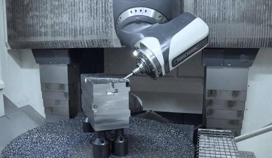
Adding a rotary axis changes the economics. A 4th-axis indexer or full 5-axis setup presents multiple faces around one clamping, reducing flips and their datums. For a cube with features on several faces — holes, pockets, chamfers — this beats hand-flipping on speed and accuracy, and is where tight squareness is easiest to hold.
Choosing the Tool: Flat vs Ball-Nose End Mills
For cube faces you want a flat (square) end mill, not a ball-nose. A ball-nose leaves a scalloped surface and cannot produce a clean flat face or a sharp external edge. Flat end mills in carbide, with 2–4 flutes, are the workhorse: they face quickly and leave a flat, crisp surface. Corner-radius end mills (a flat mill with a small chamfer on the corner) are popular because they are more robust and still leave sharp external edges on the part.
Flatness, Squareness, Parallelism (the GD&T Behind a Cube)
A good cube is defined by geometry, not just size. The drawing should call out: flatness of each face, perpendicularity (squareness) between adjacent faces, and parallelism between opposite faces. A part can be the right 25×25×25 mm and still be a poor cube if the faces are not mutually perpendicular. These geometric tolerances — not the linear dimensions alone — are what make a cube “true.”
What Tolerances Are Actually Realistic?
This is where the internet oversells. A blanket claim that milling holds “0.001 mm” on a whole cube is not credible — no shop holds that across every feature of a six-face part. What is realistic: on a well-maintained 3-axis VMC with proper fixturing, qualified flat and perpendicular features typically hold ±0.01–0.05 mm (about ±0.0004–0.002 in). Tighter bands (±0.005 mm) are achievable on selected qualified features with 5-axis positioning and CMM verification, but they cost more and should be specified only where they matter. State the tolerance you need; don’t pay for a tolerance you don’t.
Surface Finish After Milling
As-milled faces from a sharp flat mill typically land in the Ra 0.8–3.2 µm range. That suits most structural, fixture and enclosure cubes. If you need a mirror or sealing surface, plan a secondary operation — lapping, grinding or a fine skim pass — rather than expecting the roughing mill to deliver it.
Material Changes Everything: Aluminum, Steel, Plastics
Aluminum is forgiving: it mills fast, holds a great finish and is easy to square. Steels — especially hardened grades — cut slower and put more load on the tool, so squareness depends more on rigid fixturing. Engineering plastics (nylon, PEEK, acetyl) machine cleanly but can move with moisture and temperature, so verify dimensions after conditioning. The choice of stock is a design decision; see our materials guide for grade-by-grade notes.
The Corner-Radius Trap (When You Cut Into the Cube)
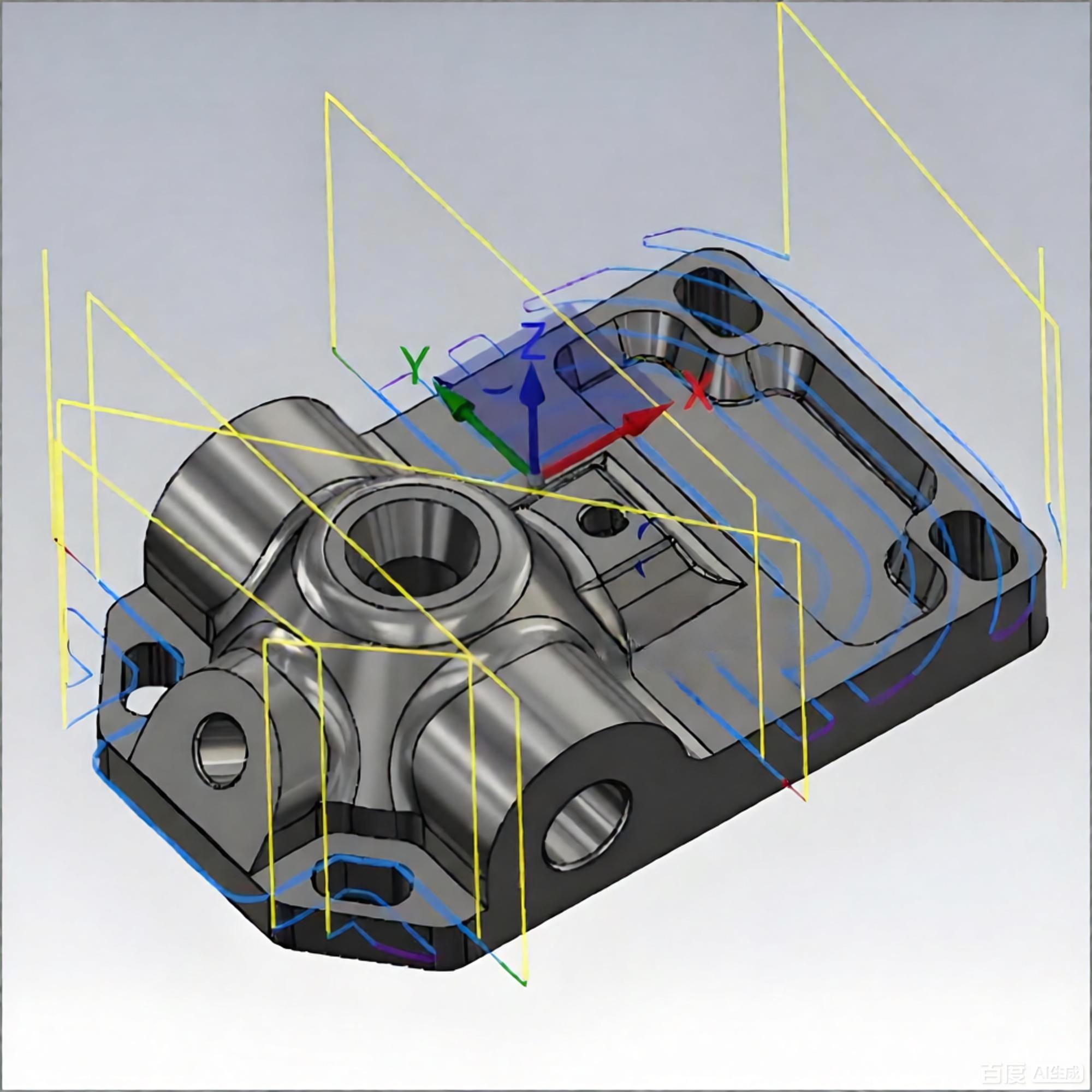
A bare cube has sharp external corners — easy. But the moment you mill a pocket, a square hole or a slot into a face, you create internal corners the round tool cannot reach. Those corners will carry a radius equal to the tool radius (or a corner-radius tool’s radius), and no amount of clever programming removes it. If your design needs a genuinely sharp internal corner, the answer is a different process: EDM, a hand broach, or a smaller tool with a subsequent operation. Design for the radius and you save cost and lead time.
Cube vs Casting: Which Is Better for a Simple Block?
If your “cube” is really a near-net-shape block with no tight features, die casting or sand casting can deliver the volume cheaply — but castings need draft angles and leave a rougher, less square blank that still wants machining on the faces that must be true. For one accurate, square cube, or low volume, machining from solid is usually simpler and more precise. Casting wins on per-part cost only at higher quantities.
Cube vs Turning: Why a Cube Needs Milling
A lathe makes round parts — shafts, discs, rings. It cannot make a cube, because a cube has flat faces and square corners that rotation cannot produce. If you are deciding between processes, read our comparison of milling versus turning: for any prismatic, multi-face part, milling (or mill-turn for combined features) is the right call.
Cube vs Grinding: When Flatness Must Be Extreme
Milling gets you a true, square cube. When the application demands ultra-tight flatness — tooling pads, optical mounts, sealing faces — a grinding pass after milling removes the last few microns. Grinding alone from raw stock is slow and expensive; the efficient route is mill to near-size, then grind the critical face. Know which faces actually need grinding and which are fine as-milled.
Mistakes That Ruin an “Easy” Cube
The usual failures are basic: using a rough sawn face as a datum, clamping so hard the part springs out of square, or over-specifying tolerance on faces that don’t need it.
Not Sure Your Cube Design Is Machinable?
If you have a drawing — even a sketch — we can review it for squareness, corner radii and tolerance realism, and tell you the most cost-effective way to make it. There is no charge for a feasibility check.
How Shops Hold Tight Tolerances on Cubic Parts
The discipline is datum control: establish one primary datum face and a second perpendicular datum, then reference every cut to them. Use light, even clamping and cut critical dimensions last.
Verifying a Cube with CMM Inspection
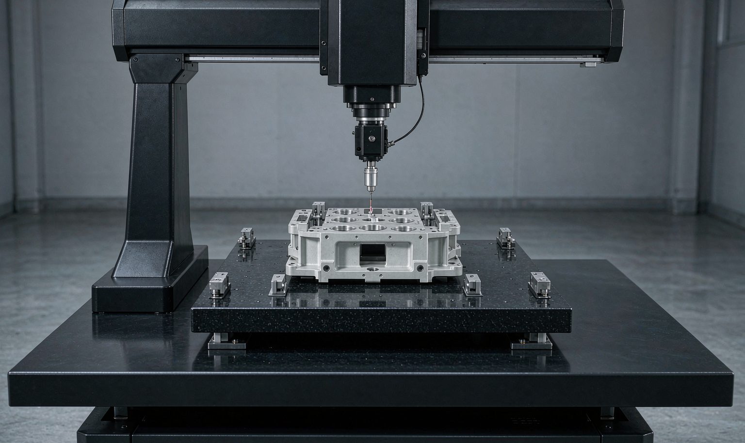
For anything beyond a casual fit, a coordinate measuring machine (CMM) confirms the cube: it probes faces and edges and reports flatness, perpendicularity, parallelism and size against the model. A good shop quotes with inspection in mind and can supply a report. This is how a ±0.01 mm claim becomes evidence rather than hope.
Design Tips to Make Your Cube Cheaper to Machine
Small changes save real money: allow the natural internal corner radius instead of demanding sharp inside corners; relax tolerance on non-critical faces; and choose stock close to the finished size so less material is removed. Our RFQ guide lists what to send for a fast, accurate quote.
When a “Cube” Is Really a Bracket, Housing, or Fixture
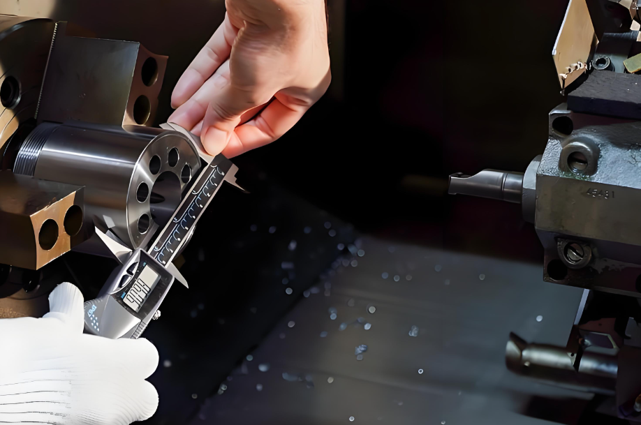
Most “cubes” we actually make are not pure cubes — they are cubic bodies with holes, threads, pockets or slots that turn them into brackets, sensor housings or fixture bases. The cube principles above still govern: face all sides, respect corner radii, control datums. Start from the cube logic and add features in order of datum importance, and the part comes out right the first time.
Frequently Asked Questions
Can a 3-axis mill make a perfect cube?
A 3-axis mill can make a true, square cube by repositioning the stock to reach all six faces. “Perfect” depends on your tolerance; typical qualified features hold ±0.01–0.05 mm, with tighter bands possible on selected features.
Why can’t an end mill cut a sharp inside corner?
The tool is round, so wherever it cuts an internal corner it leaves a radius equal to its own corner radius. Only external corners of a cube stay sharp. Sharp internal corners need EDM, broaching or a secondary operation.
Is 5-axis better for cubes?
For a plain cube, 3-axis is usually enough and cheaper. 5-axis pays off when the cube has features on several faces, because it reaches them from one clamping and reduces datum error.
What tolerance can I really expect?
Plan for ±0.01–0.05 mm on qualified features from a good 3-axis setup. Claiming a flat “0.001 mm” across an entire cube is not realistic; tighter values belong on specific, verified features.
Should I cast or machine a cube?
Machine from solid for one accurate cube or low volume. Cast only when quantity is high and the block has no tight, true faces — and expect to machine the critical faces anyway.
Need a Cube or Cubic Part Made?
Founded in 1998, we perform all six core processes in-house under one ISO 9001:2015 quality system. Send your drawing or 3D model and we will review machinability, confirm process and tolerance, and quote — from prototype to production.