Die Casting vs CNC Machining: Which Manufacturing Process Is Right for Your Project?
Compare cost, precision, materials, tooling, production volume, lead time, surface finish and applications to determine the most suitable manufacturing process for your custom parts.
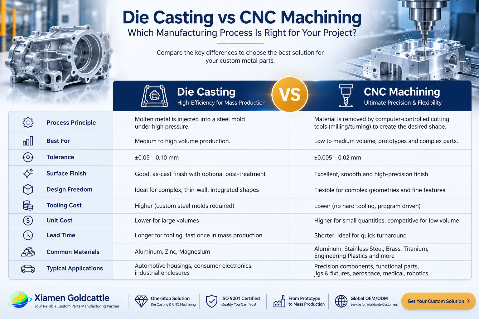
Die Casting vs CNC Machining — At a Glance
Neither process is universally "better." The right choice depends on your order quantity, tolerance needs, material, and whether the design is frozen. Use the summary below as a fast filter, then read the detailed comparison that follows.
Best Choice by Requirement
| Requirement | Best Choice |
|---|---|
| Prototype / Bridge tooling | CNC |
| High volume (10,000+ / yr) | Die Casting |
| Tight tolerance (±0.01 mm class) | CNC |
| Lowest unit cost at scale | Die Casting |
| Frequent design changes | CNC |
| Large, stable production run | Die Casting |
| Exotic / hard materials (Ti, PEEK, steel) | CNC |
| Complex thin-wall net-shape at volume | Die Casting |
Bottom line: Start with CNC for prototypes and low volume; move to Die Casting once the design is validated and annual volume justifies tooling. XM Goldcattle runs both processes in-house, so the transition is seamless.
What Is CNC Machining?
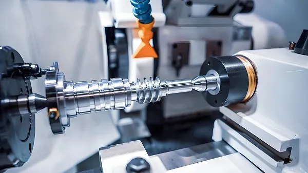
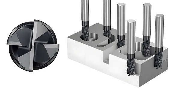
CNC (Computer Numerical Control) machining is a subtractive manufacturing process. A solid block of metal or plastic is held in a fixture and shaped by computer-controlled cutting tools — mills, lathes, routers — that remove material until the final geometry is achieved. Because the part is cut from a solid billet, its material properties are unchanged from the stock, and dimensional accuracy is limited mainly by the machine, the tool, and the measurement system rather than by a mold.
At XM Goldcattle our CNC cells routinely hold ±0.005 mm on critical features and surface finishes down to Ra 0.4 µm. The process shines when you need a handful of perfect parts tomorrow, or a few hundred parts while a design is still moving. There is essentially no tooling to amortize — you pay for machine time and material — which makes CNC the most flexible starting point for almost any custom component.
How It Works (Simplified)
Modern CNC shops run a range of equipment — 3-axis mills for straightforward prismatic parts, 4- and 5-axis machines for complex contours and fewer setups, and CNC lathes (turning centers) for round parts. Multi-axis capability matters for this comparison because it expands the geometry CNC can reach without special tooling, narrowing the gap with what die casting offers on complex shapes. The trade-off remains cycle time: a five-axis approach is precise but still removes material one pass at a time, so it does not scale to high volume the way a die does.
Best for: prototypes, low-to-mid volume, tight tolerances, hard/exotic materials, parts with internal features, and projects where the design is still changing. Explore our CNC Machining Services →
What Is Die Casting?
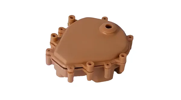
Die casting is a near-net-shape, high-pressure casting process. Molten metal — most commonly aluminum, zinc, or magnesium alloy — is forced into a reusable steel mold (the "die") under high pressure, then cooled and ejected as a solid part. Because the shape is formed in a mold rather than cut away, die casting is exceptionally fast and economical per part once the tool exists.
The trade-off is upfront investment: the die must be designed, machined, and validated before a single good part is produced. That tooling can cost from a few thousand dollars for a simple zinc part to well over six figures for a complex aluminum multi-cavity die. Die casting therefore wins decisively at volume, but it is a poor fit for one-off prototypes or designs that will keep changing. At XM Goldcattle our aluminum die casting line serves automotive, electronics, and robotics customers with stable, repeatable output.
How It Works (Simplified)
Die casting itself splits into two main methods. Hot-chamber casting suits lower-melting alloys like zinc and delivers very high cycling speeds; cold-chamber casting is used for aluminum and magnesium, where the molten metal is ladled into the chamber to protect the machine from the hotter alloy. The choice of method is determined by the alloy, not by the designer — but it affects cycle time, tool life, and cost, which is why alloy and process are decided together during engineering review.
Best for: high-volume production of thin-wall, complex housings and brackets in aluminum, zinc, or magnesium; parts where material and per-unit cost dominate the decision. Explore our Aluminum Die Casting Services →
Side-by-Side Comparison: Die Casting vs CNC Machining
This is the heart of the guide. Each row below isolates a single design or commercial variable so you can score the two processes against your own project requirements.
Manufacturing Principle
| Dimension | CNC Machining | Die Casting |
|---|---|---|
| Process type | Subtractive (material removed) | Formative (material formed in mold) |
| Starting stock | Solid billet / bar / plate | Molten alloy |
| Tooling required | Standard cutters & fixtures (low) | Reusable steel die (high) |
| Material structure | Unchanged from stock | As-cast grain; can have porosity |
| Setup flexibility | Very high — change program, not tool | Low — fixed by the die |
Read together, these rows tell a simple story: CNC is a flexible, low-commitment way to turn a digital model into metal, while die casting is a committed, high-throughput way to replicate a validated shape. The "setup flexibility" row is the one procurement teams most often underestimate. With CNC you change the part by editing a program; with die casting you change the part by reworking steel. That single difference — program versus tool — drives most real-world decisions about when to adopt, stay with, or switch processes. It also explains why CNC is the default for early-stage programs and die casting the default for mature, high-volume ones.
Materials
CNC can cut almost any machinable solid; die casting is constrained to alloys with a low enough melting point and suitable castability. The table captures the practical divide.
| Material family | CNC Machining | Die Casting |
|---|---|---|
| Aluminum | Yes | Yes (e.g. A380, ADC12) |
| Titanium | Yes | × |
| Steel / Stainless | Yes | × |
| Brass / Bronze | Yes | Limited (zinc-bronze rarely) |
| Copper | Yes | Yes (limited) |
| Zinc alloys | Yes | Yes (Zamak etc.) |
| Magnesium | Yes | Yes |
| PEEK / engineering plastics | Yes | × |
Material availability is the fastest way to eliminate one process: if your part must be titanium, tool steel, or PEEK, die casting is off the table.
Practical alloy strategy. If the application is a structural aluminum component at volume, die casting (A380, ADC12, or a custom grade) is usually ideal because the per-part economics dominate. If it is a one-off or low-volume aluminum part, CNC from 6061 or 7075 billet avoids tooling entirely and ships in days. For corrosion-resistant or high-strength requirements where only titanium or stainless will do, CNC is the only viable route. We help customers map the alloy to both the function and the process during the first engineering review, so material and process are chosen together rather than in isolation.
Tolerance
| Process | Typical achievable | Notes |
|---|---|---|
| CNC Machining | ±0.005 mm to ±0.05 mm | Depends on feature size, machine, and inspection |
| Die Casting | ±0.05 mm to ±0.15 mm (per feature) | Varies with part size, alloy, and die condition |
Tolerance is where the two processes are most often mis-specified. A common failure mode is drawing the entire part to CNC-class tolerances and then requesting die casting — the die will meet most dimensions, but the few tight ones will force secondary machining anyway, eroding the cost advantage. The efficient approach is to tolerance only the features that truly matter (mating surfaces, bores, datums) and let the process handle the rest. If you must hold ±0.01 mm on multiple faces, CNC should be the primary process or the die should be designed with post-machining locator features built in from the start.
Surface Finish
| Aspect | CNC Machining | Die Casting |
|---|---|---|
| As-produced Ra | Ra 0.4 – 3.2 µm (tool-dependent) | Ra 1.6 – 3.2 µm (as-cast) |
| Best without extra ops | Excellent — machining marks are fine/controlled | Good — but shows parting lines & ejector marks |
| Improvement path | Polish, bead blast, anodize, plating | Vibratory, blast, plate, paint, powder coat |
Design Freedom
| Design element | CNC Machining | Die Casting |
|---|---|---|
| Wall thickness | Can be thin locally; limited by stock | Uniform thin walls (0.5–1.5 mm typical) |
| Draft angle | Not required | Required (1–3° typical) |
| Undercuts | Possible with 4/5-axis & live tooling | Need slides / cores; costly |
| Internal threads | Directly cut | Usually cast + tapped, or insert |
| Holes / bores | Any size, any angle | Cast + secondary drill for tight ones |
| Complex 3D geometry | Excellent with 5-axis | Excellent for molded shapes |
CNC gives you freedom from mold constraints (no draft, easy undercuts); die casting gives you freedom from material removal (net shape, no chip waste). Choose based on which constraint hurts your design more. In practice, many production parts blend the two: a die-cast body provides the net shape and integrated ribs or bosses, while CNC cleans up the few interfaces that must be precise. Designing for that combination from day one — rather than discovering it after a die is built — is one of the highest-leverage DFM decisions a team can make.
Cost Comparison: Where the Money Actually Goes
"CNC is expensive" and "die casting is cheap" are both half-truths. The honest comparison separates fixed costs (tooling) from variable costs (per-part), because the two processes cross over at a specific volume.
Cost Components
CNC Cost Structure
- Low / near-zero upfront tooling
- Material cost = full billet (some waste)
- Machine-hour driven per-part cost
- Labour & programming per setup
- Cost per part stays roughly flat
Die Casting Cost Structure
- High upfront die / mold cost
- Low material waste (net shape)
- Very low cycle-time per part
- Die maintenance over life
- Per-part cost drops steeply with volume
The Crossover Curve
The chart below is illustrative: total cost per part falls for die casting as the fixed tooling is spread across more units, while CNC stays flat. The intersection — often in the low-thousands of parts, but highly design-dependent — is your economic break-even.
Worked Example (Illustrative)
Consider a mid-complexity aluminum bracket. Suppose a die costs $18,000 to design and build, and the cast-and-finish per-part cost is $3.20. CNC machining the same bracket from billet costs $11.00 per part with essentially no tooling. At 100 parts, CNC total cost is $1,100 versus die casting's $18,320 — CNC wins decisively. At 2,000 parts, CNC is $22,000 versus die casting's $24,400 — still close, CNC slightly ahead. At 10,000 parts, CNC is $110,000 versus die casting's $50,000 — die casting now wins by more than half. The crossover sits near 2,500–3,000 parts for this scenario. Change the die to $60,000 or the part to simpler/complex, and that number moves; the method, however, stays the same. This is exactly the model we build for customers during quoting.
Production Volume Comparison
| Annual Quantity | Recommended Process | Why |
|---|---|---|
| 1 – 50 | CNC | No tooling; fastest path |
| 100 – 500 | CNC | Tooling not yet justified |
| 1,000 – 5,000 | Mixed / Depends | Evaluate tooling payback case-by-case |
| 10,000+ | Die Casting | Tooling amortized; low unit cost |
| 100,000+ | Die Casting | Clear economic winner |
The real dividing line depends on die cost, part complexity, material, and unit price — not the calendar alone. A simple zinc clip can justify tooling under 1,000 pieces; a complex machined titanium bracket may never.
Lead Time Comparison
| Stage | CNC Machining | Die Casting |
|---|---|---|
| Tooling needed? | No | Yes — die design & build |
| First article | Days (program & cut) | Weeks (after mold done) |
| Design revision | Update program — fast | Modify die — slower & costlier |
| Ramp to volume | Add machines / shifts | Qualify die, then very fast |
At XM Goldcattle, CNC samples typically ship in 7–15 days and mass production in 15–25 days once a program is released. Die casting adds mold development time up front but then scales quickly. See the Die Casting Cost & Lead Time Guide →
Advantages Comparison
CNC Machining ✓
- No tooling investment
- Immediate start — fastest prototypes
- Best dimensional accuracy
- Any machinable material (Ti, steel, PEEK)
- Easy design changes
- Excellent for low / variable volume
- Unchanged material properties
Die Casting ✓
- Very low cost per part at volume
- Net-shape — minimal material waste
- Complex thin-wall geometries
- High repeatability once qualified
- Fast cycle times at scale
- Good mechanical consistency
- Integrates features (bosses, ribs)
Limitations Comparison
CNC Machining ×
- Material waste (chip removal)
- Higher per-part cost at scale
- Longer machine time on big runs
- Geometry limited by tool access
- Internal voids / hollows are hard
Die Casting ×
- High upfront die cost
- Material choice limited to castables
- Design changes are expensive
- Porosity risk on thick sections
- Draft angles & wall rules required
- Not viable for very low volume
Procurement teams and experienced engineers both value candid limitation sections — they signal expertise and build trust. XM Goldcattle's value is that we can recommend and run either process, so our advice is not biased toward the machine we happen to own.
Industry Comparison
| Industry | Recommended | Typical driver |
|---|---|---|
| Medical | CNC | Tight tolerance, traceable materials |
| Semiconductor | CNC | Ultra-clean, high precision |
| Automotive | Both | Prototypes CNC; high-volume cast |
| Consumer Electronics | Die Casting | Millions of thin-wall housings |
| Aerospace | CNC | Exotic alloys, certification |
| Robotics | Both | Prototype CNC; production cast |
| Industrial Equipment | Both | Mixed volumes |
Reading the table: the pattern is consistent — industries with low, uncertain, or regulated volume (medical, semiconductor, aerospace) lean CNC, while industries with massive, stable consumer volume (electronics) lean die casting. Automotive and robotics sit in the middle because they run both: CNC for development and low-volume variants, die casting for the high-run core. The right answer for your industry is therefore less about the sector label and more about your specific part's volume and tolerance profile. A medical instrument and a car mirror bracket may both be "aluminum," but their process paths are completely different.
Typical Parts by Process
Common Die Cast Parts
- Motor / pump housings
- LED & lighting enclosures
- Gearbox & transmission cases
- Consumer-electronics frames
- Brackets & heat sinks
- Cover plates & lids
Common CNC Parts
- Valve bodies & manifolds
- Impellers & rotors
- Medical instrument housings
- Fixtures, jigs & tooling
- Aerospace brackets
- Prototype & bridge parts
Explore related case studies: Aluminum Motor Housing, EV Battery Housing, Precision Valve Body.
Hybrid Manufacturing: Using CNC and Die Casting Together
The false choice between "CNC or die casting" misses the most common real-world answer: both, in sequence or in combination. Many production programs use die casting for the bulk net shape and CNC for the precision interfaces — a strategy sometimes called "cast then machine." This hybrid captures the low material and cycle cost of casting while still meeting the tight tolerances CNC is best at.
Two Ways the Processes Combine
Sequential (Lifecycle)
- CNC for prototype and bridge volume
- Die casting for stabilized mass production
- One supplier carries both phases
- DFM lessons flow from CNC into the die
Combined (Per Part)
- Die cast body with integrated ribs/bosses
- CNC finishes bores, faces, threads
- Tight features held without over-specifying the die
- Best total cost at volume + required precision
For procurement teams, the practical takeaway is to stop asking "which process" in the abstract and start asking "which process for which feature, and at what volume." That reframing is exactly what a competent manufacturing partner brings to the table — and it is why XM Goldcattle runs both processes in-house rather than pushing every inquiry toward the equipment it happens to own.
Decision Tree: Choose Your Process in 4 Questions
Follow the tree top to bottom. Each answer routes you to CNC or Die Casting. This is the same logic our engineers apply on a first inquiry.
Still unsure after the tree? That is exactly when to send us your drawing — we will score both routes and show you the cost crossover for your specific part.
Real Case Study: Robot Aluminum Housing
A robotics customer approached XM Goldcattle with a new joint-housing design. The requirements changed twice during development, and annual demand was uncertain.
What We Did
- Phase 1 — Prototype (CNC): We machined 20–50 aluminum housings from billet in 9 days. The customer validated fit, mounting, and thermal performance and revised the design twice — each revision was a quick program update, not a new tool.
- Phase 2 — Bridge (CNC): As pilot production began (a few hundred units), CNC kept supplying parts with zero tooling risk while demand proved out.
- Phase 3 — Production (Die Casting): Once annual volume crossed ~15,000 and the design froze, we built an aluminum die. Per-part cost dropped dramatically and the part kept the same envelope and critical features — with tight ones finished by secondary CNC.
Engineer's Guides: Insights You Won't Find Elsewhere
The modules below go beyond generic comparison. They reflect how XM Goldcattle's 26 years of in-house CNC and die casting experience actually drive a sourcing decision.
1. How Our Engineers Decide Between CNC and Die Casting
When an inquiry arrives, we run a fixed scoring routine rather than a gut call. First, we confirm annual volume and design stability — these two variables eliminate a process faster than anything else. Second, we check material: titanium, hardened steel, or PEEK immediately rules out die casting. Third, we assess critical tolerances and whether they sit on features a die cannot hold without secondary ops. Fourth, we model the total cost at the customer's true volume, including tooling amortization and yield. Only then do we recommend a path — and we always show the alternative with its trade-offs.
To make this concrete, a typical scoring looks like this. A part quoting 300 units/year, in 6061 aluminum, with three tight bored holes, and a design that has already gone through two revisions — scores clearly for CNC: no tooling risk, revisions are free, and the volume is far below any break-even. The same envelope at 40,000 units/year with a frozen design scores for die casting, with CNC reserved for the three bores. The discipline is not picking a favourite; it is applying the same four questions every time so the recommendation is defensible and reproducible, not dependent on who picked up the phone.
What we deliver back to the customer is a short engineering note: the recommended process, the reason, the estimated break-even volume, and — critically — the conditions under which we would switch the recommendation. That transparency is possible precisely because we operate both processes and have no incentive to steer work toward one machine.
2. Five Common Mistakes When Choosing a Manufacturing Process
- Tooling too early. Committing to a die before the design is frozen locks in expensive changes.
- Chasing the lowest unit price at low volume. Die casting's per-part savings vanish once you add unamortized tooling.
- Ignoring material limits. Specifying a castable alloy when the application needs steel or titanium.
- Forgetting secondary operations. Die cast parts often still need CNC for tight features — budget for both.
- Designing without draft or wall rules. A CNC-friendly model may be un-castable without rework.
Every one of these mistakes is avoidable with a single upstream step: a DFM review before any process is committed. At XM Goldcattle we treat that review as standard, not billable extra — because catching a draft-angle omission or an over-tightened tolerance on the drawing costs almost nothing, while discovering it after a die is cut can cost a tooling revision. The pattern across all five mistakes is the same: they come from deciding the process before understanding the part and its true volume.
3. Real Project Transition: From CNC Prototype to Die Casting Production
The robot-housing case above is not unusual. The disciplined pattern is: use CNC to de-risk the design and prove demand, then migrate to die casting for unit economics. The key is to design the CNC part with the eventual die in mind — sensible wall thickness, draft where it won't hurt function, and consolidated features — so the transition is a tooling exercise, not a redesign. We document DFM notes during the CNC phase precisely so the die quote is fast and accurate.
A frequent worry from customers is "will I lose quality moving from CNC to die cast?" The honest answer: you trade one set of controls for another. CNC quality is governed by the machine and program; die cast quality is governed by the die, the melt, and the process window. Both are controllable to high repeatability when run by an experienced supplier. The parts that suffer in transition are those where tight features were specified everywhere; the parts that succeed are those where only the functional interfaces were tightened and the rest left to the process. That is the difference between a transition planned around DFM and one discovered after the fact.
4. Tolerance Recommendations by Industry
| Industry | Typical tolerance expectation | Process fit |
|---|---|---|
| Medical instruments | Very tight (±0.01 mm class) | CNC primary |
| Semiconductor | Ultra tight, clean | CNC |
| Automotive structural | Moderate, functional | Both (cast + CNC features) |
| Consumer electronics | Cosmetic + assembly | Die casting |
| Robotics | Mixed | Both |
These are planning ranges, not specs. Final tolerances are agreed per drawing after DFM review.
5. Design Optimization Tips Before Tooling (DFM)
- Standardize wall thickness to avoid porosity and sinking.
- Add 1–3° draft on die-cast faces; skip it for CNC.
- Place critical tolerances on features that survive the chosen process without secondary ops where possible.
- Consolidate ribs and bosses to reduce part count.
- Reserve CNC for the few features a die truly cannot hold — do not over-specify the whole part.
The single most valuable DFM habit is to ask, for every dimension on the drawing, "does this truly need to be this tight?" Every tolerance you relax is a cost you remove from the process — whether that is machine time on CNC or die complexity and secondary ops on casting. Equally important is involving manufacturing engineering before the design is released, not after quotes come back high. At XM Goldcattle the DFM review happens at inquiry, so the part that reaches tooling or the CNC queue is already optimized for the process it will run on.
Frequently Asked Questions (20)
Can die casting replace CNC machining?
Which is cheaper: die casting or CNC machining?
Which is more accurate, die casting or CNC?
Which has better surface finish?
Which process produces stronger parts?
Which is faster to start production?
What is the minimum order quantity for die casting?
Can you CNC machine die cast parts?
Is die casting suitable for prototypes?
What materials cannot be die cast?
How long does die casting tooling take?
What wall thickness is possible with die casting?
Do die cast parts need draft angles?
Can die casting achieve tight tolerances?
Which process is better for aluminum parts?
What are common die casting defects?
Is CNC machining wasteful?
Can die casting be used for small batches?
How do I choose between CNC and die casting?
Why start with CNC prototype then move to die casting?
Glossary: Terms Used in This Comparison
A quick reference for the manufacturing terms referenced above, useful when reading quotes or engineering drawings.
| Term | Meaning |
|---|---|
| Die / Mold | The reusable steel tool used in die casting to form the part shape. Distinct from the "mold" used in injection molding, though the concept is similar. |
| Draft angle | A slight taper (typically 1–3°) on die-cast surfaces parallel to the ejection direction so the part releases from the die. CNC parts need none. |
| Net shape | A part produced at or very near final geometry with minimal material removal. Die casting is net-shape; CNC is subtractive. |
| Porosity | Micro-voids that can form inside cast metal, especially in thick sections. Managed through design and process control. |
| DFM | Design for Manufacturability — adapting the design to suit the chosen process (draft, wall thickness, radii) before tooling. |
| Break-even volume | The annual quantity at which total cost (tooling + per-part) of die casting drops below CNC. Below it, CNC is cheaper; above it, die casting is. |
| Secondary operation | Any post-process step (CNC, tapping, finishing) applied after the primary process to meet spec. |
| Cavity | One part-forming impression in a die. Multi-cavity dies produce several parts per shot, lowering per-part cost. |
| Parting line | The seam on a cast part where the two die halves meet; visible and a tolerance consideration. |
| Bridge / prototype tooling | Lower-cost temporary tooling used to validate a design before committing to full production tooling. |
| A380 / ADC12 | Common die-cast aluminum alloys; A380 is widely used in North America, ADC12 in Asia. Both offer good castability. |
| 5-axis CNC | A machine that moves the tool or part on five axes, enabling complex 3D geometry and fewer setups. |
What to Send Us for the Most Accurate Recommendation
The fastest way to get a reliable CNC-vs-die-casting recommendation is to share a little context up front. You do not need a finished drawing — even a sketch plus the points below lets our engineers score the two processes for you.
- Target annual volume (and whether it is expected to grow over the program life).
- Material preference or constraint (for example, must be aluminum, or must be non-magnetic, or must withstand a temperature).
- Critical dimensions and tolerances that truly matter for function, not the whole drawing at maximum tightness.
- Stage of the program — concept, prototype, pilot, or full production.
- A 3D model or 2D drawing if available, in STEP, IGES, or PDF format.
- Surface finish and post-processing expectations such as anodizing, painting, or plating.
With those inputs we return a short engineering note: the recommended process, the estimated break-even volume, a price indication, and the conditions under which we would switch the recommendation. That is the same decision logic summarized on this page, applied to your specific part rather than to a generic case.