"Can You Actually Program Impeller Flow Passages and Blade Surfaces?"
The 12-Step Workflow That Gets Your Complex Toolpaths Right Before Cutting
Owning a 5-axis machine and having simultaneous 5-axis manufacturing capability are different things. The difference is the programming workflow between your CAD model and the machine's G-code. This page documents every step our CAM engineers complete before a tool touches your material — with specific focus on impeller, blade and contoured-surface programming where tool-axis control determines success or scrap.
The Short Answer
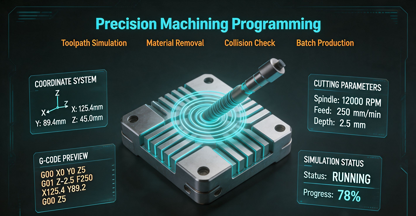
Yes — with the caveat that impeller and blade programming requires a systematic workflow that most general-machine shops skip or compress. Our approach:
- We use dedicated multi-axis CAM software (tool-vector control, lead/tilt optimisation, holder-reach analysis) — not 3-axis toolpaths forced through a post-processor.
- Every program passes through full kinematic simulation including machine structure, fixture, tool holder assembly and part geometry before any material is cut.
- Each machine platform runs its own verified post-processor — a program validated on one machine is not automatically safe on another, even from the same builder.
- The 12-step workflow below is executed for every simultaneous 5-axis job; shortcuts are the leading cause of collision damage and profile non-conformance on complex parts.
Why Impeller and Blade Programming Is Different
Impeller flow passages and turbine blade profiles represent the most geometrically demanding category of 5-axis machining work. Understanding why they are hard explains why the programming workflow matters.
The Geometric Challenges
- Narrow passages: blade spacing often limits tool diameter to 6–12 mm while passage depth exceeds 30–60 mm → extreme length-to-diameter ratio, high deflection risk
- Continuous curvature: hub-to-blade-to-fillet surfaces have no flat regions; tool axis must change smoothly along the entire path to avoid gouging
- Twisted airfoil sections: blade pressure and suction surfaces have different curvature radii that may require different tilt strategies on each side
- Thin trailing edges: easily deflected or torn by excessive cutting force or improper lead angle
- Hidden interference zones: the tool holder can collide with adjacent blades during deep-passage cuts even when the cutter itself clears
- Surface-finish requirements: flow surfaces typically require Ra 0.8–1.6 µm (aluminium) or Ra 1.6–3.2 µm (stainless/titanium) for aerodynamic performance
What Goes Wrong Without Proper Workflow
| Gouging | Cutter removes material from an adjacent blade or hub fillet it should not touch |
| Holder collision | Tool holder (not the cutter) contacts the part or fixture during a tilted pass |
| Axis singularity | Rotary axes approach a position where small toolpath changes cause large rotary movements → surface marks or axis alarm |
| Step marks at blend lines | Visible seam where roughing/semi-finishing/finishing zones meet due to inconsistent stock allowance |
| Tool breakage in passage | Excessive engagement angle or chip packing in narrow channel causes cutter failure mid-cut |
| Profile out-of-tolerance | Final surface deviates >0.03–0.05 mm from CAD nominal due to uncorrected tool deflection or thermal drift |
The 12-Step CAM Workflow — Every Simultaneous 5-Axis Program
This sequence is not optional. Each step addresses a specific failure mode. Skipping or compressing steps is the statistical leading cause of 5-axis machining quality events on complex contoured parts.
CAD Model & Drawing Review
Import STEP/IGES model. Verify model integrity (no gaps, overlaps or corrupted surfaces). Cross-check critical dimensions against 2D drawing. Flag ambiguous tolerances or missing GD&T datums before proceeding.
Datum and Stock Definition
Establish work coordinate system aligned to drawing datum A-B-C. Define stock envelope (billet size, cast/forged near-net shape, or pre-machined blank). Confirm material removal ratio to plan stress-management strategy.
Fixture and Clamping Model
Model fixture geometry in CAM environment: locators, clamps, clamp-clearance zones, and any portion of the fixture that enters the machine's working envelope. Include soft-jaw profiles if used.
Roughing Strategy
Select roughing method based on geometry: zoned roughing for impellers (divide into accessible zones), cavity roughing for housings. Set controlled stock allowance (typically 0.3–0.8 mm depending on material). Plan tool entry/exit paths to avoid full-width engagement.
Tool-Axis Control Setup
Define lead/tilt strategy per region: normal-to-surface for finishing, away-from-point for impeller hubs, curve-based for blades, fixed-tilt for semi-finishing. Set maximum angular change rate to avoid jerky rotary motion (typically 3°–5° per segment max).
Reach and Holder Analysis
Define complete tool assembly: cutter diameter, corner radius, flute length, shank diameter, holder type (BT/HSK/SK), gauge length, pull-stud protrusion. Run reach analysis for every operation to confirm holder clearance at maximum tilt attitude.
Full Machine Kinematic Simulation
Run simulation with complete digital twin: machine kinematics (axis travels, rotary limits, pivot point), fixture model, tool assembly and part stock. Verify no collisions throughout the entire toolpath at programmed feed rate.
Collision and Over-Travel Check
Systematic check: tool-to-part, tool-to-fixture, holder-to-part, holder-to-fixture, holder-to-machine structure, table-to-spindle at all index positions. Flag and resolve every interference before post-processing.
Post-Processor Validation
Generate G-code through machine-specific post-processor. Verify RTCP/TCPM compensation is active (critical for simultaneous 5-axis). Check rotary-axis output format matches control system requirements. Validate at machine limits.
Controlled First-Piece Run
First article cut at reduced feed rate (typically 50–70% of production feed) with increased inspection frequency. Verify dimensional results against CAM stock predictions before releasing to production feed.
In-Process Measurement
On-machine probing at critical stages: after roughing (verify stock distribution), after semi-finishing (confirm finish allowance), after finishing (detect thermal drift or tool wear before part is unclamped).
Final Dimensional Verification
CMM inspection referenced to drawing datum scheme. Surface-profile deviation report for contoured features. Compare results to CAM predictions; document discrepancies for process adjustment on subsequent parts.
Tool-Axis Control: The Technical Core
Tool-axis control is what separates simultaneous 5-axis programming from indexed positioning. It defines how the cutter tilts relative to the part surface as it moves along the toolpath. Getting this wrong causes gouging, poor surface finish, or tool breakage.
Lead and Tilt Strategy
Lead angle: forward/backward tilt in the feed direction. Tilt angle: side tilt relative to surface normal.
- Typical lead angle: 5°–15° forward to avoid cutting with ball-nose tool center (zero surface speed at center)
- Side tilt: 2°–5° to prevent tool rubbing on one flank
- Variable lead/lag: higher lead on convex blade surfaces, near-zero lag on concave curves
- Why it matters: incorrect lead causes center-cutting marks; excessive tilt risks holder contact with adjacent geometry
Common Axis-Control Modes
Each mode suits a specific geometric challenge.
- Normal to Surface: tool perpendicular to surface — best for general finishing of freeform shapes
- Away from / Toward Point: tool aims toward or away from a focal point — ideal for impeller hubs and spherical cavities
- Curve-Based: tool axis follows a guide curve — standard for turbine blades and propeller-type geometries
- Fixed Tilt: constant tilt angle — used for semi-finishing and roughing where simplicity reduces risk
Collision Avoidance System
Automatic and manual layers working together.
- Holder clearance verification: minimum safe distance (typically 2 mm) checked at every toolpath point
- Safe-zone definition: angular ranges where tool axis is permitted to operate; automatic avoidance outside these ranges
- Linking retract strategy: how the tool moves between passes (along axis, along surface normal, or via defined clearance plane)
- Singularity management: detection and avoidance of rotary-axis positions where small toolpath changes cause large axis movements
CAM Software, Post-Processors and Why Platform-Specific Matters
Our 5-axis platforms differ in kinematics, rotary configuration and control system. A program validated on one platform is not automatically safe on another.
| Consideration | DMG MORI DMU 50 | Mazak 5-Axis Platform | Why It Matters for Your Part |
|---|---|---|---|
| Kinematic configuration | Swivel rotary table (B + C axes) | Tilting rotary (specific config confirmed at quotation) | Determines how rotary motion translates to tool-tip position; post-processor must match exactly |
| Control system | Siemens / Heidenhain (confirmed at quotation) | Mazatrol / CNC (model-specific) | RTCP/TCPM implementation differs between controls; G-code format and rotary-addressing are not interchangeable |
| Pivot point | Specific to table centre and trunion height | Specific to head/table configuration | Incorrect pivot point = all 5-axis positions offset by a constant error proportional to tilt angle |
| Post-processor status | Dedicated verified post for each control variant | Dedicated verified post for each control variant | Generic post-processors are a common source of 5-axis positioning errors; we do not use them |
Frequently Asked Questions
What CAM software do you use for 5-axis programming?
How long does 5-axis CAM programming take compared to 3-axis?
Can you machine impellers and bladed components?
Do you simulate every program before cutting?
Have a Complex Contoured Part That Needs 5-Axis Programming?
Upload your 3D model. We will run it through our 12-step workflow assessment, identify the tool-axis strategy, flag any reach or collision concerns, and give you a clear answer on feasibility — before you commit to anything.
STEP / IGES / Parasolid accepted. Response within 1–2 business days. Confidentiality guaranteed.