Precision simultaneous 5-axis CNC machining for complex multi-surface parts, curved geometries, deep cavities and difficult-to-access features. From prototypes and low-volume parts to repeat production, Goldcattle provides engineering review, machining and dimensional inspection for global buyers.
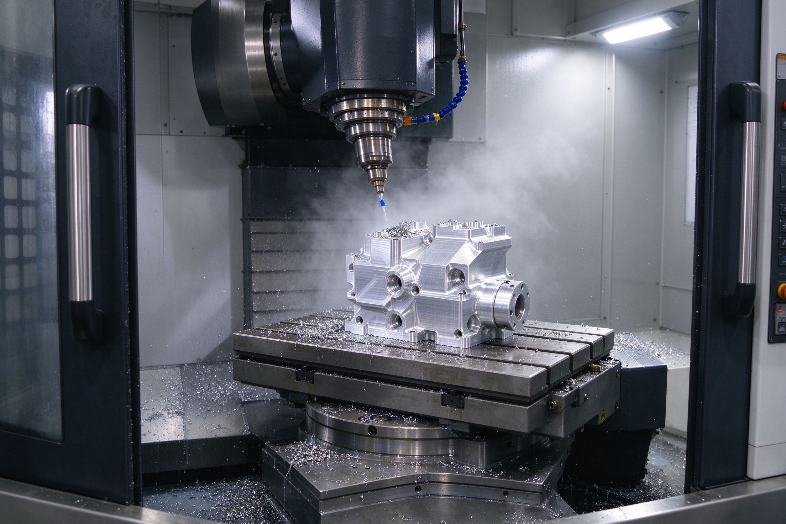
Yes — a China-based 5-axis shop can machine your complex part correctly and repeatedly when the drawing defines the geometry, datums, tolerances and inspection plan. The difference between shops shows up in four places: how the part is programmed, how it is held, how the machine is chosen for the feature, and how the result is verified. Goldcattle reviews geometry in DFM, programs and simulates the toolpath, machines on verified 5-axis equipment, and checks critical features on a CMM against your drawing — not a generic tolerance claim.
A 5-axis CNC machine has five axes of motion — typically X, Y, Z plus two rotary axes, here B and C. The value is not the axis count: the rotary axes let the tool and workpiece be oriented so the cutter reaches multiple faces, keeps a useful tool angle on curved or steep geometry, and stays short and rigid.
"5-axis" is often used loosely. Distinguish two modes before quoting or ordering:
| Mode | How it works | Typical use |
|---|---|---|
| 3+2 (positioned) | Workpiece or tool is rotated to a fixed angle, then machined with 3-axis motion. | Multi-face parts, angled holes, indexed features; shorter, stiffer tools. |
| Simultaneous 5-axis | Linear and rotary axes move together during cutting. | Curved surfaces, impellers, blades, continuously changing tool orientation. |
Not every part benefits from 5-axis. The decision comes from geometry, datums and tool access — review these before assuming the axis count matters:
| Part characteristic | Why 5-axis may help |
|---|---|
| Multiple critical faces | Fewer setups; features on different faces share one datum frame. |
| Compound-angle features | Tool can approach at the required angle without angled fixtures. |
| Deep cavities | Tool orientation keeps the cutter short and reduces reach-limited deflection. |
| Undercuts | Tool approach from multiple directions reaches geometry a 3-axis spindle cannot. |
| Complex 3D contours | Continuous tool orientation keeps cutting conditions consistent. |
| Closely related datums | Reduced re-fixturing reduces datum-transfer and stack-up risk. |
| Blades / impellers | Tool must track the surface while avoiding adjacent blades. |
| Sculpted surfaces | Improved surface-quality potential on suitable geometry. |
5-axis is not automatically better for every part. A good supplier selects the simplest process that meets the drawing — see when 5-axis is not necessary below. For the decision logic between information and machining, the standalone guide when should I use 5-axis CNC machining covers the reasoning in more depth.
Choose the axis configuration from the geometry, not from habit. The table is a first pass; the final call is made in the engineering review.
| Requirement | 3-Axis | 4-Axis | 5-Axis |
|---|---|---|---|
| Flat / prismatic parts | Suitable | Suitable | — |
| Side features on multiple faces | — | Suitable (one rotary) | Suitable |
| Multiple angled faces | — | Partial | Suitable |
| Complex compound surfaces | Partial | Partial | Suitable |
| Deep / difficult access | Partial | Partial | Suitable |
| Setups expected | More likely | Reduced | Often reduced |
| Highly complex contours | Limited | Moderate | Strong fit |
The appropriate axis configuration depends on geometry, datum structure, tolerance, tool access, quantity and cost. Axis count is a means, not the specification.
Every re-fixturing introduces risk: the part is re-located, datums are re-transferred, and alignment errors accumulate across features. On parts with several critical faces, that accumulation is often the real accuracy problem — more than any single machining operation.
Setup 1 → Setup 2 → Setup 3 → Setup 4. Each step adds datum transfer and fixture-positioning error.
Fewer re-locations; features share one datum frame; feature-to-feature relationships stay consistent.
Rigorous statement: 5-axis can reduce the number of setups for suitable geometries. It does not guarantee one-setup completion on every part — actual setup strategy depends on geometry, workholding, access requirements and critical datums. No shop should promise "everything in one setup" without reviewing the part.
5-axis quality is set in programming before any tool moves. The CAM workflow below is the chain a buyer should expect a supplier to describe:
Identify what limits access
Undercuts, deep cavities, compound surfaces, tool-reach limits and holder clearance mapped before toolpath planning.
Set the tool axis
Tool-axis angle selected per feature so the cutter stays short, avoids collisions and keeps effective cutting conditions.
Check tool · holder · part
Tool, holder, spindle, fixture and workpiece verified in simulation before cutting.
Control load first
Material removal balanced to limit vibration, heat and tool wear on the material concerned.
Prepare the surface
Uniform stock left for finishing so the final pass engages consistently.
Control scallop & deviation
Stepover, tool engagement and tolerance set against the required surface finish and profile deviation.
Verify before cutting
Toolpath simulation checks collisions, machine motion and final geometry before the first chip.
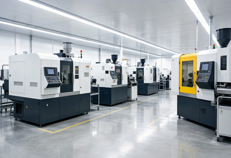
Machines are the controlled base, not the selling point. The platform list below is the current verified equipment used for complex work:
| Platform | Configuration | Typical work |
|---|---|---|
| DMG MORI DMU 50 | Simultaneous 5-axis, B + C rotary | Complex multi-face components, curved parts, aerospace-adjacent geometry |
| Mazak 5-axis machining center | 5-axis, where verified per project | Multi-face housings, angled features |
| 3 / 4-axis milling & turning | Support equipment | Prismatic and rotational features routed to the simplest suitable process |
Equipment is confirmed per project before quotation; platform choice follows the geometry, material and tolerance, not the other way around.
Capability is a system, not a spindle. The usable result of a 5-axis part depends on all of these working together:
Condition & kinematics
Calibrated axes and a post-processor matched to the machine's motion model.
Verified toolpaths
Collision-checked, simulated programs before cutting.
Datum control
Fixturing that holds the datum scheme defined on the drawing.
Correct reach & rigidity
Tool length and diameter chosen for access without deflection.
Grade-specific strategy
Cutting parameters set for the actual alloy and condition.
Method matches claim
CMM and instruments appropriate to the tolerance being verified.
When evaluating a supplier, ask how these six work together on your part — not only what machines are on the floor.
5-axis is a process, not a material promise. Capability is confirmed by alloy grade, geometry, size, condition and inspection requirements — not by a blanket "we machine everything."
| Material group | Grades typically machined | 5-axis consideration |
|---|---|---|
| Aluminum | 6061-T6, 7075-T6, 2024, 6063 | High removal rates; good for complex multi-face housings and brackets. |
| Stainless steel | 304, 316L, 17-4 PH | Higher cutting forces; tool access and rigidity matter on thin walls. |
| Titanium | Ti-6Al-4V / Grade 5 | Heat management and chip evacuation govern finishing quality. |
| Difficult-to-machine | Inconel 718, tool steels, selected engineering plastics | Heat, work hardening and tool engagement controlled in strategy, not in marketing. |
For material-specific machining detail, see aluminum machining best practices and the Ti-6Al-4V machining guide.
Difficult materials reward process control. The same alloy machines well or poorly based on how the shop manages heat, load and tool engagement:
| Material | Primary challenge | Process response |
|---|---|---|
| Titanium | Heat concentration at the cutting edge | Coolant at the cut, positive engagement, controlled chip load. |
| Inconel 718 | Heat, work hardening, tool wear | Consistent engagement, tool-life monitoring, rigid setup. |
| Hardened steel | Tool wear, spindle load | Hard-machining tooling, rigid spindle, staged passes. |
Each alloy is reviewed per project — grade, condition and required finish — before cutting parameters are fixed.
A machine's advertised positioning resolution is not the same as the final dimensional capability of a finished part. Accuracy on a real part is the result of a chain:
Size, walls, access
Feature size and reachable tooling set what can be controlled.
Datum stability
The part moves under load, accuracy moves with it.
Heat drift
Machine, tool and part expand; thermal stability shapes repeatability.
Dimensional drift
Wear moves the effective cutting edge across a run.
Approximation & engagement
Tolerance and stepover in CAM set geometry fidelity.
Method & datums
How features are measured defines what is actually confirmed.
For the tolerance methodology itself, the tight-tolerance CNC machining guide covers the approach in detail.
Tolerance is not one number, and surface finish is not one Ra. Both are set per feature, per drawing:
| Tier | Scope | Verification |
|---|---|---|
| ±0.05 mm | General machining; non-critical and cosmetic dimensions. | Caliper / standard instruments |
| ±0.01 mm | Controlled finishing; features needing better-than-general control. | Micrometers, bore gauges |
| ±0.005 mm (qualified) | Selected CTQ features only: bearing seats, locating surfaces, hole position, flatness — confirmed by CMM. | CMM |
Tolerances down to ±0.005 mm may be supported on qualified features, subject to material, geometry, feature size, machining process, datum structure and inspection requirements. Over-tolerancing raises cost without improving function; express CTQ features with datums and feature-control frames.
Finish on a 5-axis contour is governed by tool orientation, tool diameter, stepover, feed rate, material, tool condition and finishing strategy. A required Ra value changes the finishing pass; it is defined per feature and measurement method, not as a blanket claim. Ra 0.8 μm on one surface may be routine while another feature on the same part is specified as-machined.
Inspection is a closed loop, not a final check. The chain below is what a buyer should expect from drawing to release:
Align to the drawing
Part setup and measurement align to the datum scheme on the drawing.
Control drift
Critical features checked during machining where the operation allows.
Confirm GD&T
Position, profile, flatness and related datums verified on a Zeiss Prismo CMM (±0.0005 mm capability).
First article
First article inspection against the drawing before repeat production where required.
Document the result
Dimensional inspection report accompanies the parts; material certificate per EN 10204 3.1 available.
Ship with evidence
Parts released against the inspection plan agreed at quotation.
The inspection method must match the tolerance claimed — a caliper cannot confirm a ±0.005 mm feature. For a walkthrough of inspection and documents on a difficult material, see the Ti-6Al-4V guide.
Impellers & rotors
Curved blades and closed channels need continuous tool orientation.
Turbine blades
Aerofoil surfaces and tight profile control.
Aerospace structural parts
Multi-face brackets and thin-wall structures with related datums.
Engine & fluid components
Manifolds, housings and flow geometry with angled features.
Medical orthopedic components
Complex curved implants and instruments (ISO 13485-aligned controls).
Complex housings
Multi-face enclosures where fewer setups protect datum consistency.
Mold & tooling components
Shaped inserts and tooling with difficult access.
Robotic & automation parts
Custom joints and precision interfaces machined from solid or near-net stock.
Industry labels are only useful when tied to the procurement scenario behind them:
| Industry | What drives 5-axis use | Buying scenario |
|---|---|---|
| Aerospace | Lightweight structures, contoured surfaces, multi-face machining | Prototype brackets and structural parts; documentation per project |
| Medical | Complex curved implants and instruments | ISO 13485-aligned controls; material and inspection per drawing |
| Robotics | Multi-face housings, custom joints, precision interfaces | Small batches with tight feature relationships |
| Automotive / motorsport | Prototype parts, complex aluminum components | Design iteration and low-volume runs |
| Energy / fluid control | Impellers, manifolds, flow-related geometry | Qualified features and documented inspection |
5-axis work often starts as one part to prove geometry and ends as repeat production. The continuity matters: the same drawing, process plan and inspection method should carry across the lifecycle.
Prove geometry & fit
DFM review, machining, dimensional check; drawing changes fed back.
Fix the route
Setup plan, toolpath and inspection method locked for repeat.
Confirm stability
First article inspected; process adjusted before scaling.
Hold the standard
Same drawing, process and quality requirements across orders.
For the full lifecycle model, see prototype to production in China.
Buyers often shortlist suppliers before the first call. Use this table as the verification list:
| Factor | What to ask |
|---|---|
| Machine | What actual 5-axis machines are used, and are they verified per project? |
| Axis type | Simultaneous 5-axis, 3+2, or both — and which fits your part? |
| CAM | How are complex toolpaths verified before cutting? |
| Workholding | How are critical datums maintained across features? |
| Materials | Which alloys have actual production history, at what grades and conditions? |
| Tolerance | Which features can be held, and how are they inspected? |
| Metrology | Is a CMM available, and does the inspection method match the tolerance claimed? |
| Documentation | FAI, dimensional report, material certificate — what is delivered? |
| Production | Prototype through repeat production under one process plan? |
| Communication | Who handles engineering review, and in which language/format? |
| Factory model | In-house manufacturing or a supplier network? |
| Lead time | What is included in the quoted lead time — machining only, or review + inspection + documentation? |
Cross-border procurement is managed in five layers. None of them is a marketing promise; each is a process question:
CAD / drawing / DFM
Files exchanged, geometry reviewed, open questions resolved before cutting.
CMM / FAI / material cert
Inspection results and certificates delivered with the parts.
Status & revisions
Project status and drawing revisions tracked through the order.
Packing / shipping / docs
Export documents, packing and delivery arranged per order.
Same drawing, same process
Repeat orders run against the locked process and quality requirements.
The quote is only as accurate as the information behind it. Send:
3D CAD + 2D drawing
STEP, IGES or native model, plus a dimensioned drawing with GD&T.
Material & quantity
Grade, condition and prototype-vs-production intent.
Critical features
CTQ dimensions, datum scheme, GD&T and surface finish per feature.
Quality requirements
CMM report, FAI, material certificate, traceability or special inspection standard.
Context
Application, annual volume, target delivery and any coating or heat-treatment needs.
Missing data forces assumptions; the best quotes come from a complete file and a short engineering conversation.
5-axis can cost more per machine hour and in programming — and less in setups, handling and accumulated risk. Judge the total project, not the hourly rate:
Machine hourly rate · CAM programming · setup / fixturing · inspection · specialized tooling.
Setup count · fixture changes · secondary operations · manual handling · accumulated alignment risk · cycle time on suitable parts.
The comparison that matters is total project cost at the required quantity — including programming, inspection and repeatability — not machine-hour rate alone.
Representative jobs show how the workflow maps to real parts. Values are characteristic of defined projects, not standard claims; each order is quoted from its own drawing and validated plan.
- PartImpeller, 17 curved blades
- Diameter248 mm (representative)
- ProcessSimultaneous 5-axis
- EquipmentDMG MORI DMU 50
- Tolerance / finish±0.005 mm CTQ · Ra 0.8 μm
- InspectionFAI + CMM dimensional report
- Lead time8 working days (representative)
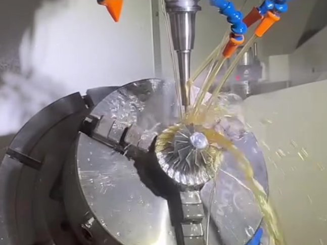
Challenge: 17 curved blades with restricted access; tool orientation had to track the surface while avoiding adjacent blades. Process: CAM-verified toolpaths, continuous 5-axis motion, controlled engagement in a work-hardening alloy. Inspection: first article CMM-measured before any repeat work. Result: dimensional report confirmed conformance to the drawing and validated plan.
- MaterialTi-6Al-4V (Grade 5)
- GeometryComplex curved, thin features
- Process5-axis machining + finishing
- ControlsISO 13485-aligned
- InspectionCMM + surface verification
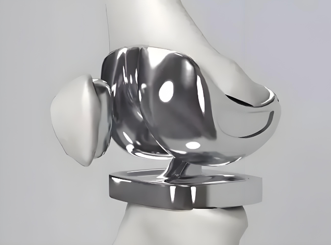
Challenge: curved, thin titanium geometry sensitive to heat and deflection. Process: rigid workholding, coolant at the cut, short tool reach and controlled finishing passes. Inspection: critical dimensions and surface verified per the drawing. Result: first article released against the agreed inspection plan.
- PartMulti-face housing, angled features
- Material6061-T6
- Process5-axis, reduced setups
- Key requirementFeature-to-feature datum control
- InspectionCMM on critical datums
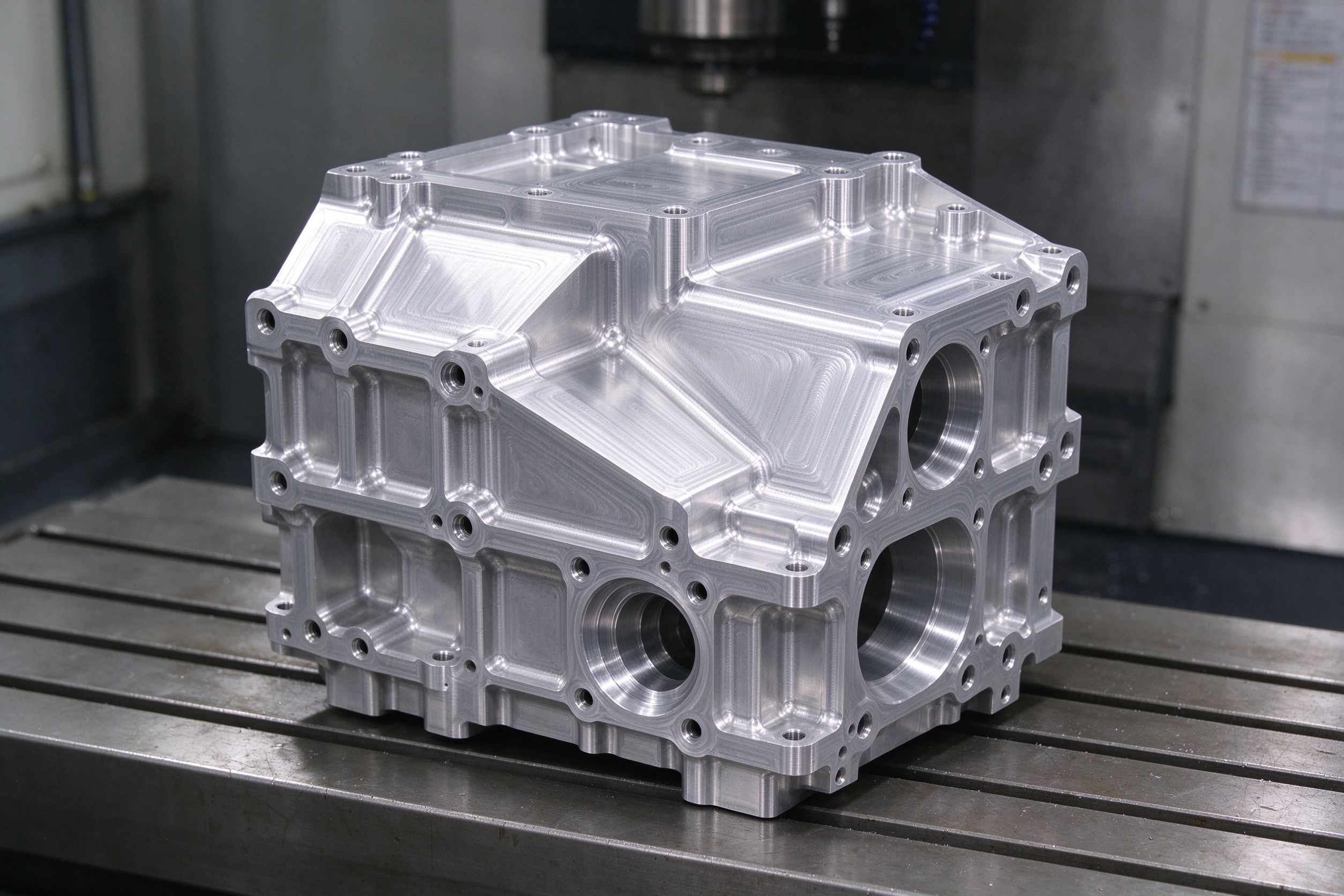
Challenge: four critical faces with positional relationships that would have required multiple setups. Process: simultaneous 5-axis with controlled workholding and verified CAM toolpaths. Inspection: critical datums and features CMM-measured. Result: dimensional report confirmed conformance; repeat production ran against the locked process.
A capable shop says this plainly:
Simple 3-sided parts
Standard prismatic geometry on a 3-axis machine meets the drawing.
Large flat plates
No rotary benefit; 3-axis is faster and cheaper.
High-volume simple components
Volume economics favor the simplest stable process.
Tolerance already met on 3-axis
Extra axes add cost without adding function.
A good supplier selects the simplest process that can meet the part's functional and quality requirements. The CNC machining services overview shows the full process range available.
What is 5-axis CNC machining?
What is simultaneous 5-axis machining?
What is the difference between 3+2 and simultaneous 5-axis machining?
When should I use 5-axis instead of 3-axis?
Does 5-axis always provide better accuracy?
What parts are suitable for 5-axis CNC machining?
What materials can be 5-axis machined at Goldcattle?
What tolerance can 5-axis CNC machining achieve?
What should be included in a 5-axis CNC RFQ?
How is a China 5-axis CNC supplier evaluated?
Does 5-axis reduce manufacturing cost?
How are complex 5-axis parts inspected?
Send your CAD model and drawing. We can review the geometry and datum structure, select the machining strategy, and define the inspection and documentation plan for your program — before you commit to a quote.